The popularity of the optocoupler based on the pc817 transistor is very high. It is included in almost any electroplated switching power supply with feedback.
The device has a very convenient body. The distance between the leads is 2.54 mm, the rows are spaced 7.62 mm apart.
The main manufacturer of PC817 is Sharp; other electronics factories produce PC817 analogues. By the way, when repairing various electronics, people often first come across substitutes, for example, SFH618 from Siemens or TLP521-1 from Toshiba. There are also double and triple versions of the original: PC827 and PC837.
But it is more profitable to use not a multi-channel substitute, but a certain number of PC817.
How to check an optocoupler with a multimeter?
You won’t be able to simply check the optocoupler with a multimeter. For the simplest test of an optocoupler, you need to apply voltage to its input (according to the diagram), and check the output with a multimeter in diode test mode.
Check procedure
The test is carried out with a conventional tester, switching the device to the range for measuring diodes or resistance.
Connecting a multimeter for testing
How to test a resistor with a multimeter
The element-by-element description of the check looks like:
- the resistance measurement mode is selected on the device;
- the tester probes are connected to the pins of the part;
- The instrument readings displayed on the display are evaluated.
When the multimeter’s own power supply is connected with a positive probe to the anode, the display can record resistance readings from a few fractions of an ohm to its units. After replacing the measuring probes with a working element, an infinitely large resistance is obtained.
Keeping in mind that the zener diode behaves like a simple diode, set the measurement interval in kOhms. In this case, the resistance of a working radio component reaches hundreds of kOhms.
Information. The readings displayed on the display by the tester often mislead the person conducting the measurement. The same high resistance with different probe connections does not always mean a breakdown of the element. The internal source voltage supplied for measurements may exceed the rated breakdown voltage, then the results obtained will be false.
Optocoupler tester
Radio amateur forums often contain the opinion that since the element is inexpensive, then why is a pc817 test needed? It is enough just to change it on time.
In fact, everything is not quite like that. You need to understand whether the optocoupler has burned out or not in order to conclude whether anything else has been damaged. It happens that new optocouplers burn out because they have a manufacturing defect.
How to test pc817? To do this, ring the light diode using a tester. First, find out if there is a short circuit in the transistor. Afterwards, pass current through the light diode and make sure the transistor opens.
You can create a simple device for testing optocouplers at home. For this you will need:
- LEDs - 2 pieces.
- Buttons - 2 pieces
- Resistors - 2 pieces.
Light diodes must correspond to a current strength of 5 to 20 mA and a voltage of approximately 2 V. In this case, the two resistors should have a resistance of around 300 V.
The tester's power source is a USB port with a voltage of 5 V. But you can also use 3-4 2A batteries. 9-12 V batteries or a power source with the same voltage will also work. Only here you will have to recalculate the resistances of the two resistors.
Now let's look at how an optocoupler works, based on various experiments.
Optocoupler testing device
To more conveniently check the optocoupler, you can use a more interesting circuit. It includes a minimum of components, and assembly takes no more than half an hour.
The optocoupler is powered through an LED, which will light up if the photoemitter is working. The second LED will light up if the photodetector through which current flows to the LED is working.
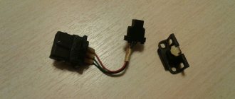
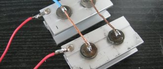
For clarity, the second version of the diagram was assembled from elements that were at hand. The role of the test subject is played by the optocoupler PC817.
The role of the socket for connecting the optocoupler is performed by the remains of the COM cable. But it is better to use sockets for microcircuits for such purposes, then connecting the optocoupler will become more convenient.
The circuit is powered using an old USB cord. In general, the circuit works properly right away and does not require additional adjustment. If both LEDs are lit, then the optocoupler can be considered working.
Many people will have a question: if the output of the optocoupler is broken, then both LEDs will also light up! In this case, the brightness of the second LED will be much higher, it will be visually very visible.
How to make simple optocoupler devices yourself
You can find the pc817 optocoupler in a phone charger or computer power supply, so getting one is not at all difficult. Based on it, a simple LED flasher with a stroboscopic effect is assembled.
You need to have with you:
- 4.2V power supply part.
- Light diode with any color.
- Resistors with resistances of 5.6 and 1 kOhm, respectively.
- Optocoupler based on transistor pc817.
- Capacitor with a capacity of 220 μF and a voltage of 10 V.
The first step is to consider the optocoupler itself. It includes 2 parts that are connected by optical communication. In other words, when voltage is applied to the light diode, the internal transistor opens.
Keep in mind that the point is the first reference contact. Inside the element itself, these contacts are 4. 1 and 2 refer to the input through which the internal light diode is connected. And 3 and 4 are the output.
Using this simplest radio element, an elementary generator with repeating pulses is created. There is no need to configure the circuit and install fully serviceable elements there. Assembly is done by surface mounting without using a board.
- Clamp the optocoupler with a clamp and solder 2 resistors.
- Then solder the light diode. Keep in mind, it turns on in polarity.
- After this, solder the capacitor.
- The next stage is the creation of connecting tracks from tinned wires.
- Solder the contacts of the part for power supply.
- If the flasher begins to perform its function (that is, blink), then it is working properly.
- The capacitance of the capacitor is needed directly to regulate the blinking frequency.
- If you have problems starting, check that the polarity of all parts is correct. The exception is resistors.
This simple scheme can be applied in different areas.
We all know that in most industrial devices it is very important to detect the isolated mains voltage in time. With the help of insulation, here it is necessary to prevent the flow of current (direct or alternating) from the first half of the structure to the other, and also to ensure the transmission of signal and power.
Thanks to insulation, you can isolate potential differences, make the device resistant to interference and protect it from strong voltage surges. Typically, DC or AC optocouplers are needed to detect voltage. They need to be installed on the path where the signal passes.
Under no circumstances should you touch the board when the device is already turned on. This results in electric shocks.
How to build an AC power detector
The PC817B optocoupler contains an infrared light diode that is coupled optically to a photographic transistor. That, in turn, is placed in a dip package with 4 contacts. The standard insulation voltage at input-output is 5 kV, at collector-emitter - up to 80 V, CTR can be up to 600% at an input current of 5 mA.
The circuit does not require an AC transformer. To reduce the voltage, a series capacitor is used, which is connected directly to a network with a voltage of 220 V. A diode is used to rectify the alternating current voltage, and the final voltage at direct current is corrected by the capacitor.
The zener diode is a pre-regulator to completely protect the circuit. If there is a break on the capacitor, for example, if a resistor accidentally burns out, the capacitor voltage does not exceed 5 V. Therefore, the filter capacitor cannot explode.
The resulting input causes a low output signal during a suitable interface with an external structure where there is a pull-up resistor. If the power is turned off, a high-level output signal appears.
It is possible to create an improved version of such a network detector, which will be adjusted to digital technology. It is clear that the most basic and safe way to determine electricity in the network is using a microcontroller. You can't do without an optocoupler here. To safely connect PC817 such a high voltage (220 V) to an optocoupler, a current limit is needed. Due to its magnitude, the resistor power rating must be taken into account.
For a smooth, stable output of a constant current, for example, if we are talking about a GPIO microcontroller, a slight modification of the circuit is needed. The capacitance of the capacitor does not matter much here. It can range from 2 to 10 µF.
Application of 2-directional optocoupler
There is another current option - the use of a 2-directional optocoupler. In another way it is called an AC optocoupler. It includes a pair of internal light diodes. They are directed in the opposite direction. One such model is H11AA1.
Thanks to the design of the conceived universal detector, monitoring a high-voltage signal becomes easier. It helps to ensure the formation of a digital output signal with electroplating. There are no expensive elements in the scheme. It can be assembled within an hour.
The project includes 2 important fragments. One of them processes the high-voltage input, the second isolates the low-voltage section from the high-voltage one. And to enhance circuit protection, you cannot do without a fuse and a metal oxide varistor.
The variator is based on metal oxide. It is a resistor that depends on voltage. It is unique and protects circuits from excess voltage. Thanks to him, fluctuations in this indicator are reduced.
Under normal conditions, the varistor has a high resistance, but when the connected voltage increases, compared to the limit of the variator, it immediately decreases. A varistor can be easily connected between phase and zero, but only after the fuse. Then, if the varistor short circuits, the device will be disconnected from the network due to the fuse.
It is possible to use a pull-up resistor for microcontrollers that do not have this element inside. Moreover, using a two-pin jumper, the correction capacitor is turned on or off, if necessary.
The final unsmoothed output signal is not perfectly smooth, but its fluctuations are no more than 500 mV. The input to this optocoupler is connected to the mains voltage, which is processed by a potential capacitance divider circuit. The highest possible switching voltage of the optocoupler is 30 V, and the transistor that is connected to the output of the optocoupler can withstand a current of up to 10 mA.
One example of using a sensor is when it is a reset circuit at the moment it is connected to the network. The second option is an emergency current system, a microcontroller alarm, or a power failure/resume identifier circuit.
Checking with a tester
Since the zener diode and the diode have almost the same current-voltage characteristics with the exception of the breakdown section, the zener diode is checked with a multimeter, just like the diode.
The test is carried out with any multimeter in the mode of diode ringing or resistance determination. The following actions are performed:
- the switch sets the Ohm measurement range;
- measuring probes are connected to the terminals of the radio component;
- the multimeter should show units or fractions of ohms if its internal power supply is connected positive to the anode;
- By swapping the probes, we change the polarity of the voltage at the terminals of the semiconductor and get a resistance close to infinity, if it is working properly.
We recommend reading: Three-position switch: biscuits, with zero position, packet and with fixation
To make sure that the zener diode is working, switch the multimeter to the resistance measurement range in kilo-ohms and take a measurement.
With a working device, the readings should be in the range of tens and hundreds of thousands of ohms. That is, it passes current like a regular diode.
PC817 connection diagram
It is common, as for all transistor optocouplers. The input current must be limited. You can use a resistor for this. The output current must also not be exceeded.
Pc817 connection circuit 372 can be seen in the figure:
PC817 specifications in Russian
PC817 LED parameters:
- Forward current - 50 mA.
- The maximum forward current is 1 A.
- The voltage in the opposite direction is 6 V.
- Dissipated power - 70 MW.
Parameters of phototransistor PC817
Its parameters are as follows:
- The voltage between collector and emitter is 35 V.
- Emitter-collector - 6 V.
- Collector current - 50 mA.
- Dissipated collector power - 150 mW.
We must not forget about one more important parameter. It is called the current transfer ratio, CTR. Its unit of measurement is %. In the optocoupler designation in the pc817 datasheet, it corresponds to the letter following the main code, as in other pc817 optocouplers and semiconductors.
How to test a bipolar transistor with a multimeter
Testing a bipolar transistor with a multimeter allows you to identify a faulty component or determine the location of the terminals (collector K, emitter E and base B). To know how to check the functionality, it is necessary to imagine an analogue of the transistor circuit in the form of two back-to-back (pnp) or reverse (npn) diodes connected with a middle point, which is equivalent to the base terminal. And the remaining two are identical to the emitter and collector pins. For direct conduction transistors, the cathodes are connected to the base (“sticks” according to the diagram), and the anodes (“arrows”) are connected to the reverse conduction. When you connect a red diode (positive wire) to the anode and a black diode to the cathode, the tester will show some value on the indicator. If it is very small, it means that the diode being measured is broken. And if it’s very large, then the diode is broken.
Normal values for the resistance of the emitter or collector junction lie in the range of 0.4 - 1.6 kOhm, depending on the specific transistor. By connecting the transistor terminals in pairs with the multimeter probes, pairs of terminals “B-E” and “B-K” are determined. The K-E transition resistance is always very high. If the pair is not found or the resistance of the collector-emitter junction is small, then the transistor is faulty. It is worth considering that the collector resistance in relation to the base is always less than the resistance of the B-E junction, which will help determine the pinout of a serviceable part.
The above is true both when checking a direct conduction transistor and an npn structure transistor. In the latter case, measurements are carried out with the tester wires connected in reverse polarity.
Tsokolevka
With the PC817 pinout, everything is more or less clear. The device is housed in a 4-pin DIP package. It uses both surface and hole mounting.
There is a depressed dot on one of the contacts that points towards the anode of the light diode from the inside. The legs are numbered clockwise. The second one is the cathode. Pins number 3 and 4 are the emitter and collector.
Modern versions of the device have been tested with good results in accordance with international standards. They are safe to use and difficult to ignite, as stated in the pc817 datasheet.
How to test a field effect transistor
For field-effect transistors, the terminals are called drain (C), source (I) and gate (G). Despite the fact that the physics of operation differs from bipolar, when checking for serviceability, you can also use the diode equivalent of the circuit.
The p-type field effect transistor test circuit is similar to the pnp test. Before checking, it is necessary to connect all the terminals to discharge the junction capacitances. The resistance when connecting probes to pairs of terminals “C, Z” and “I, Z” should be shown only in one of the directions. We connect the black probe to the “C” terminal, and the red one to the “I” terminal. The value of the shown resistance (400-700 Ohms) must be remembered. After this, we connect the red wire to the gate for a second, thereby opening the transition. After this, we measure the transition resistance. Its decrease indicates that the transistor has partially opened. Now we also connect the black wire to terminal “Z” and close the transition. Restoring the initial value of the transition resistance indicates the serviceability of the radio component. The difference between testing an n-type field device is only in changing the polarity of connecting the probes of the device.
We recommend reading: DIY DC voltage multiplier
When testing insulated gate field effect transistors, the absence of conductivity between the gate and source is checked. Then we combine the source with the gate. Bilateral conductivity will appear in a depletion type transistor. For enriched type parts the conductivity will be one-sided.
Varieties
You can come up with a lot of appointments for such a duet, and this mass is divided, according to the principle of operation, into three types. In the first case, the Receiver records the very fact of the presence of a signal at the emitter. Is there something shining for him or not? This circuit is used, for example, to transfer any information between two independent and galvanically unconnected electrical circuits. In this case, the optocoupler is called galvanic isolation. The signal can be, for example, a voltage source of 12V or 220V, and the receiving side operates on 3.3V logic, so as not to burn the second one first, we use an optocoupler. Cheap, reliable and safe. In the second case, the emitter always shines, but we control the presence or absence of obstacles between the source and the receiver. These types of devices are used as a more accurate and durable alternative to limit switches. A good example is 3D printers. In more expensive models, optocouplers are used as sensors for extreme positions of the printing unit and stage. The rest envy them and strive to quickly upgrade their capricious mechanical limit switches. The third type is console. The emitter does not shine directly on the receiver, but the receiver is still able to pick up this light if it is successfully reflected from any surface. It is used to determine the presence of a surface in principle or its individual properties, such as color. These types of sensors are widely used to create boring cars that drive along the black line, which is already a kind of “Hello World!” in the world of budding robotics enthusiasts.
Checking a composite transistor with a multimeter
How to test a Darlington transistor? You can check a compound transistor in the same way as a bipolar one, using a digital multimeter with continuity testing of transistors in diode testing mode. The only difference is that the direct voltage to the pair of terminals B-E should be 1.2-1.4 volts. If the existing device cannot provide this, testing is impossible. And then it is better to use a simple probe using a 12 V battery, a 22 kOhm resistor included in the base and a 5 W car light bulb. Next, we connect the “minus” of the source to the emitter, and connect the collector to the lamp. We connect the second terminal of the lamp to the “plus” of the battery. If you connect a resistor to the positive terminal, the light will light up. Now we switch the resistor to “plus” - the light goes out. This means that the transistor being tested is working.
Connection diagram
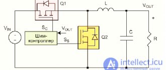
The standard PC817 connection circuit is presented by the manufacturer in the datasheet. It can be used to describe the operation of the device. To open the transistor at the output, power must be supplied to its input. This is usually done through a current-limiting resistor RD, so as not to burn the device.
To determine the value of this resistor RD, you need to know: what power will be supplied to the input (V), the voltage drop across the internal LED (VF) and the forward current (IF) for maximum opening of the transistor at the output of the optocoupler.
When calculating the resistor for the pc817 optocoupler, use the formula according to Ohm's law RD=(V-VF)/IF. Parameter values are taken from the datasheet: typical VF = 1.2 V, forward current recommended in the “measurement conditions” column IF = 20 mA (0.02 A). For example, for a supply voltage of 5 V at the input RD=(5-1.2)/0.02 = 190 Ohm.
How to check a transistor without unsoldering it from the installation
You can check the transistor with a multimeter after checking the circuit to identify possible short-circuiting of the terminals of the element being tested with low-resistance resistors. If any are found, the part will have to be removed to check. If not, the check is performed using the methods described above, but the reliability of the testing will be low. Sometimes desoldering the base output is enough.
It is better to check field-effect transistors separately from the board. They are very sensitive to static electricity, so it is necessary to use an antistatic wrist strap.
Main causes of malfunction
The most common reasons for a triode element in an electronic circuit to fail to operate are as follows:
- Break in the transition between components.
- Breakdown of one of the transitions.
- Breakdown of the collector or emitter section.
- Power leakage under voltage.
- Visible damage to the terminals.
Characteristic external signs of such a breakdown are blackening of the part, swelling, and the appearance of a black spot. Since these shell changes occur only with high-power transistors, the issue of diagnosing low-power ones remains relevant.
An even easier way to test the PC817 optocoupler
It is clear that using a Chinese tester to test an optocoupler is not the simplest, or rather simple but not the cheapest method. Not everyone has such a device on their household.
Therefore, I bring to your attention a simpler, and most importantly, cheaper optocoupler tester.
It consists of two buttons, two resistors, an LED and a socket for a microcircuit.
Description, characteristics, Datasheet and methods for testing optocouplers using the example of PC817.
Continuing the topic “Popular radio components for repairs of switching power supplies,” we will analyze one more part - optocoupler (optocoupler) PC817. It consists of an LED and a phototransistor. They are not electrically connected to each other, thanks to which, based on the PC817, it is possible to implement galvanic isolation of two parts of the circuit - for example, with high voltage and low voltage. The opening of the phototransistor depends on the illumination of the LED. I will discuss how this happens in more detail in the next article, where in experiments, by feeding signals from the generator and analyzing it with an oscilloscope, you can understand a more accurate picture of the operation of the optocoupler.
Checking the optocoupler
To quickly test the optocoupler, I conducted several test experiments. First on the breadboard.
Option on breadboard
As a result, we were able to obtain a very simple circuit for testing the PC817 and other similar optocouplers.
First version of the scheme
I rejected the first option for the reason that it inverted the transistor marking from npn to pnp
Therefore, to avoid confusion, I changed the diagram to the following;
Second version of the scheme
- Optocoupler P817
The second option worked correctly, but it was inconvenient to solder the standard socket
SCS-8
for a microcircuit
Panel SCS-8
Third version of the scheme
The most successful
Uf is the voltage on the LED at which the phototransistor begins to open.
in my version Uf = 1.12 Volts.
The result is a very simple design:
- Photodiode, phototransistor, photothyristor, optocoupler, types of indicators
View from above
Bottom view
As you can see from the photo, the part is not rotated according to the key.
Using which you can very quickly check the part. In my practice of repairs, of course, not often, but I have come across non-working optocouplers and before I had to bother checking the part when sometimes I came to a dead end during a complex repair.
The final option is very simple.
Classification of types of optocouplers
There are several characteristics according to which optocoupler models can be divided into several groups.
Depending on the degree of integration:
- elementary optocoupler - includes 2 or more elements united by a common housing;
- optocoupler integrated circuit - the design consists of one or more optocouplers and, in addition, can also be equipped with complementary elements (for example, an amplifier).
We recommend reading: Pinout of different types of USB connectors: pinout of micro and mini usb, pinout features
Depending on the type of optical channel:
- Open type optical channel;
- Closed optical channel.
Depending on the type of photodetector:
- Photoresistor (or simply resistor optocouplers);
- Photodiode optocouplers;
- Phototransistor (using a conventional or composite bipolar phototransistor) optocouplers;
- Photothyristor or phototriac optocouplers;
- Optocouplers operating using a photovoltaic generator (solar battery).
The design of devices of the latter type is often supplemented with field-effect transistors, the same generator is responsible for controlling the gate.
Phototriac optocouplers or those equipped with field-effect transistors may be called “optorelays” or “solid state relays”.
Fig. 1: Optocoupler device
Optoelectronic devices operate differently depending on which of the two types of directions they belong to:
- Electro-optical.
The operation of the device is based on the principle according to which light energy is converted into electrical energy. Moreover, the transition is carried out through a solid body and the internal photoelectric effect processes occurring in it (expressed in the emission of electrons by the substance under the influence of photons) and the glow effect under the influence of an electric field.
- Optical.
The device operates through the subtle interaction of solids and electromagnetic radiation, as well as using laser, holographic and photochemical devices.
Photonic electronic computers are assembled using one of two categories of optical elements:
- Optocouplers;
- Quantum optical elements.
They are models of devices of the electron-optical and optical directions, respectively.
Whether the optocoupler will transmit the signal linearly is determined by the characteristics of the photodetector built into the design. The greatest transmission linearity can be expected from resistor optocouplers. As a result, the process of operating such devices is most convenient. A step lower are models with photodiodes and single bipolar transistors.
To ensure the operation of pulsed devices, optocouplers based on bipolar or field-effect transistors are used, since there is no need for linear signal transmission.
Finally, photothyristor optocouplers are mounted to ensure galvanic isolation and safe operation of the device.
Principle of operation
As you can easily guess from the name, the device consists of a pair of elements somehow related to optics. That’s right, the first is a light emitter, the second is a receiver. Any source from the visible or invisible spectrum can be used as an emitter: LED, laser, wax candle, or even an Ilyich light bulb. As a receiver: phototransistor, photodiode, less often a camera. An optocoupler can be made as a single, ready-to-use device containing both elements in one housing, in which case it is also known under the general name “optocoupler”. Less commonly, an optocoupler can be two separate devices that interact with each other at a distance without physical contact. Despite the difference in designs, their operating principle is the same - the emitter transmits the signal, the receiver receives. Why this is needed and how to use it in practice, we will consider further.