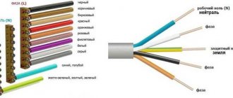
Installation and maintenance work in electrical installations is associated not only with ensuring reliability, but also safety. Complete error elimination is required. For these purposes, a system of color designations for core insulation has been developed, which determines what color the wires are phase, neutral and ground.
According to the PUE, the following colors of current-carrying conductors are allowed:
- red;
- brown;
- black;
- gray;
- white;
- pink;
- orange;
- turquoise;
- purple.
The above list contains many options for wire colors, but there are not several colors that are used only to indicate neutral and protective wires:
- blue color and its shades - working neutral wire (neutral - N);
- yellow with a green stripe - protective earth (PE);
- yellow-green insulation with blue marks at the ends of the conductors - combined (PEN) conductor.
It is allowed to use conductors with green insulation with a yellow stripe for grounding, and for combined conductors blue insulation with yellow-green marks at the ends.
The color must be the same in each circuit within one device. Branch circuits must be made with identically colored conductors. The use of insulation without differences in shades indicates a high standard of installation and greatly facilitates further maintenance and repair of equipment.
Regulations
Taking into account the large number of electrical elements, a number of normative documents have been developed for their alphanumeric (hereinafter referred to as BO) and conventional graphic designations (UGO) to eliminate discrepancies. Below is a table showing the main standards.
Table 1. Standards for graphic designation of individual elements in installation and circuit diagrams.
| GOST number | Short description |
| 2.710 81 | This document contains GOST requirements for BO of various types of electrical elements, including electrical appliances. |
| 2.747 68 | Requirements for the dimensions of displaying elements in graphical form. |
| 21.614 88 | Accepted codes for electrical and wiring plans. |
| 2.755 87 | Display of switching devices and contact connections on diagrams |
| 2.756 76 | Standards for sensing parts of electromechanical equipment. |
| 2.709 89 | This standard regulates the standards in accordance with which contact connections and wires are indicated on diagrams. |
| 21.404 85 | Schematic symbols for equipment used in automation systems |
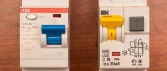
It should be taken into account that the element base changes over time, and accordingly changes are made to regulatory documents, although this process is more inert. Let's give a simple example: RCDs and automatic circuit breakers have been widely used in Russia for more than a decade, but there is still no single standard according to GOST 2.755-87 for these devices, unlike circuit breakers. It is quite possible that this issue will be resolved in the near future. To keep abreast of such innovations, professionals monitor changes in regulatory documents; amateurs do not have to do this; it is enough to know the decoding of the main symbols.
Types of electrical circuits
In accordance with ESKD standards, diagrams mean graphic documents on which, using accepted notations, the main elements or components of a structure, as well as the connections connecting them, are displayed. According to the accepted classification, there are ten types of circuits, of which three are most often used in electrical engineering:
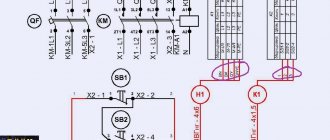
- Functional, it shows the node elements (depicted as rectangles), as well as the communication lines connecting them. A characteristic feature of this scheme is minimal detail. To describe the main functions of nodes, the rectangles displaying them are signed with standard letter designations. These can be various parts of the product that differ in functionality, for example, an automatic dimmer with a photo relay as a sensor or a regular TV. An example of such a scheme is presented below.
Example of a functional diagram of a television receiver - Fundamental. This type of graphic document displays in detail both the elements used in the design and their connections and contacts. The electrical parameters of some elements can be displayed directly in the document, or presented separately in the form of a table.
Example of a circuit diagram of a milling machine
If the diagram shows only the power part of the installation, then it is called single-line; if all elements are shown, then it is called complete.
Single Line Diagram Example
- Electrical wiring diagrams. These documents use positional designations of elements, that is, their location on the board, method and order of installation are indicated.
Installation diagram of a stationary flammable gas detector
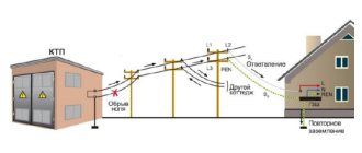
If the drawing shows the wiring of the apartment, then the locations of lighting fixtures, sockets and other equipment are indicated on the plan. Sometimes you can hear such a document called a power supply diagram; this is incorrect, since the latter shows how consumers are connected to a substation or other power source.
L and N in electrics - color coding of wires
The vast majority of cables have different colors of core insulation. This was done in accordance with GOST R 50462-2009, which sets the standard for ln marking in electrical installations (phase and neutral wires in electrical installations). Compliance with this rule guarantees fast and safe work for a technician at a large industrial facility, and also allows you to avoid electrical injuries during independent repairs.
Variety of colors of electrical cable insulation
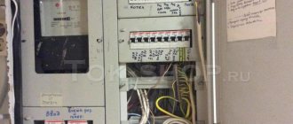
The color marking of wires is varied and varies greatly for grounding, phase and neutral conductors. To avoid confusion, the PUE requirements regulate what color ground wire to use in the power supply panel, and what colors must be used for zero and phase.
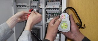
If the installation work was carried out by a highly qualified electrician who knows modern standards for working with electrical wires, you will not have to resort to using an indicator screwdriver or a multimeter. The purpose of each cable core is deciphered by knowing its color designation.
Graphic symbols
Each type of graphic document has its own designations, regulated by relevant regulatory documents. Let us give as an example the basic graphic symbols for different types of electrical circuits.
Examples of UGO in functional diagrams
Below is a picture depicting the main components of automation systems.
Examples of symbols for electrical appliances and automation equipment in accordance with GOST 21.404-85
Description of symbols:
- A – Basic (1) and acceptable (2) images of devices that are installed outside the electrical panel or junction box.
- B - The same as point A, except that the elements are located on the remote control or electrical panel.
- C – Display of actuators (AM).
- D – Influence of MI on the regulating body (hereinafter referred to as RO) when the power is turned off:
- RO opening occurs
- Closing RO
- The position of the RO remains unchanged.
- E - IM, on which a manual drive is additionally installed. This symbol may be used for any RO provisions specified in paragraph D.
- F- Accepted mappings of communication lines:
- General.
- There is no connection at the intersection.
- The presence of a connection at the intersection.
UGO in single-line and complete electrical circuits
There are several groups of symbols for these schemes; we present the most common of them. To obtain complete information, you must refer to the regulatory documents; the numbers of state standards will be given for each group.
Power supplies.
To designate them, the symbols shown in the figure below are used.
UGO power supplies on schematic diagrams (GOST 2.742-68 and GOST 2.750.68)
Description of symbols:
- A is a constant voltage source, its polarity is indicated by the symbols “+” and “-”.
- B – electricity icon indicating alternating voltage.
- C is a symbol of alternating and direct voltage, used in cases where the device can be powered from any of these sources.
- D – Display of battery or galvanic power supply.
- E- Symbol of a battery consisting of several batteries.
Communication lines
The basic elements of electrical connectors are presented below.
Designation of communication lines on circuit diagrams (GOST 2.721-74 and GOST 2.751.73)
Description of symbols:
- A – General display adopted for various types of electrical connections.
- B – Current-carrying or grounding bus.
- C – Designation of shielding, can be electrostatic (marked with the symbol “E”) or electromagnetic (“M”).
- D - Grounding symbol.
- E – Electrical connection with the device body.
- F - On complex diagrams, consisting of several components, a broken connection is thus indicated; in such cases, “X” is information about where the line will be continued (as a rule, the element number is indicated).
- G – Intersection with no connection.
- H – Joint at intersection.
- I – Branches.
Designations of electromechanical devices and contact connections
Examples of the designation of magnetic starters, relays, as well as contacts of communication devices can be seen below.
UGO adopted for electromechanical devices and contactors (GOSTs 2.756-76, 2.755-74, 2.755-87)
Description of symbols:
- A – symbol of the coil of an electromechanical device (relay, magnetic starter, etc.).
- B – UGO of the receiving part of the electrothermal protection.
- C – display of the coil of a device with mechanical interlock.
- D – contacts of switching devices:
- Closing.
- Disconnecting.
- Switching.
- E – Symbol for designating manual switches (buttons).
- F – Group switch (switch).
UGO of electric machines
Let us give several examples of displaying electrical machines (hereinafter referred to as EM) in accordance with the current standard.
Designation of electric motors and generators on circuit diagrams (GOST 2.722-68)
Description of symbols:
- A – three-phase EM:
- Asynchronous (squirrel-cage rotor).
- The same as point 1, only in a two-speed version.
- Asynchronous electric motors with phase-phase rotor design.
- Synchronous motors and generators.
- B – Collector, DC powered:
- EM with permanent magnet excitation.
- EM with excitation coil.
Designation of electric motors on diagrams
UGO transformers and chokes
Examples of graphic symbols for these devices can be found in the figure below.
Correct designations of transformers, inductors and chokes (GOST 2.723-78)
Description of symbols:
- A – This graphic symbol can indicate inductors or windings of transformers.
- B – Choke, which has a ferrimagnetic core (magnetic core).
- C – Display of a two-coil transformer.
- D – Device with three coils.
- E - Autotransformer symbol.
- F – Graphic display of CT (current transformer).
Designation of measuring instruments and radio components
A brief overview of the UGO of these electronic components is shown below. For those who want to become more familiar with this information, we recommend viewing GOSTs 2.729 68 and 2.730 73.
Frequency converter ER-02T-6R5S2 - 6.5 kW, 24A, 220V
Price: 42840 rub.
- Description
- Characteristics
- Connection diagram
- dimensions
- Description
- Downloads
There are no downloads.
| Property | Meaning | |
| Nutrition | Rated mains voltage, V | Single phase 220V 50Hz |
| Output characteristics | Rated engine power, kW | 6,5 / 9 / 11 / 13 |
| Rated motor current, A | 24 / 32 / 37 / 45 | |
| Operating current overload, A | 120% for 1 minute, 150% for 6 seconds | |
| Output frequency range | 0 | |
10 V (100 kOhm) / 4
Control terminals
Programmable current outputs 4
Programmable relay outputs, load up to
250V/3A, = 30V/1A RC-RB: normally closed; RC-RA: Normally open.
Power terminals
Main characteristics
Connection to the network according to the scheme “single-phase input 220V - three-phase output”
| Rated power | 6.5 kW |
| Output current | 24 A |
| Input voltage | Single phase 220V 50Hz |
| Output voltage | Three-phase 220V 0-120Hz |
| Series | ERMAN ER-02T-220 |
The first single-phase frequency generator is a transformer.
The design of the frequency converters of this series allows it to be mounted both along the wide and along the narrow side of the housing.
Built-in DC motor braking eliminates the need for external braking units and braking resistors.
Application area
Single-phase frequency converters ER-02T work both with motors of pumps, fans, compressors, molding machines, and in cases where increased accuracy of motor torque control is required, for example, in lifting and transport, machine tools.
Letter designations
In electrical diagrams, in addition to graphic symbols, alphabetic symbols are also used, since without the latter, reading the drawings will be quite problematic. Alphanumeric marking, just like UGO, is regulated by regulatory documents, for electrical this is GOST 7624 55. Below is a table with BO for the main components of electrical circuits.
Letter designations of main elements
Unfortunately, the size of this article does not allow us to provide all the correct graphic and letter symbols, but we have indicated regulatory documents from which all the missing information can be obtained. It should be taken into account that current standards may change depending on the modernization of the technical base, therefore, we recommend monitoring the release of new additions to regulations.
Graphic
As for the graphic designation of all elements used in the diagram, we will provide this overview in the form of tables in which the products will be grouped by purpose.
In the first table you can see how electrical boxes, panels, cabinets and consoles are marked on electrical circuits:
The next thing you should know is the symbol for power sockets and switches (including walk-through ones) on single-line diagrams of apartments and private houses:
As for lighting elements, lamps and fixtures according to GOST are indicated as follows:
In more complex circuits where electric motors are used, elements such as:
It is also useful to know how transformers and chokes are graphically indicated on circuit diagrams:
Electrical measuring instruments according to GOST have the following graphic designation on the drawings:
By the way, here is a table useful for novice electricians, which shows what the ground loop looks like on a wiring plan, as well as the power line itself:
In addition, in the diagrams you can see a wavy or straight line, “+” and “-”, which indicate the type of current, voltage and pulse shape:
In more complex automation schemes, you may encounter incomprehensible graphic symbols, such as contact connections. Remember how these devices are designated on electrical diagrams:
In addition, you should be aware of what radio elements look like on projects (diodes, resistors, transistors, etc.):
That's all the conventional graphic symbols in the electrical circuits of power circuits and lighting. As you have already seen for yourself, there are quite a lot of components and remembering how each is designated is possible only with experience. Therefore, we recommend that you save all these tables so that when reading the wiring plan for a house or apartment, you can immediately determine what kind of circuit element is located in a certain place.
Interesting video on the topic:
3-phase motor wiring 220 V
I have a pump motor that I was trying to connect to.
It's been a long time since I connected the motor and I haven't seen it with only 4 wire connections - U, V, W and ground. I have 220v 3 ph. Can I plug it directly into a connector that can be plugged in to turn the engine on and start? Or should I have a controller?
Also, my red and black wires go to the U and V terminals and the neutral wire to the W terminal? This other terminal is ground.
Thanks for the help!
2 answers
U, V and W are all strength. The earth is obviously the earth. Ugh, I can't read Chinese.