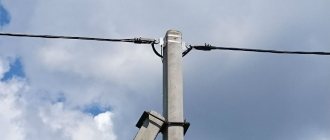
To transmit electrical energy through power and lighting overhead lines, a self-supporting insulated wire (SIP) is used. Lines using this type of cable were invented in the 60s by Finnish engineers as an alternative to using bare wires that were suspended on cables. This method of energy transmission ensures minimal losses and is suitable for installation on existing power transmission poles.
What is SIP wire
To understand the purpose and design of the cable, you first need to decipher the markings:
- C – self-supporting;
- I – isolated;
- P – wire.
This cable is used for laying electrical transmission lines over the air. This is an ideal option when installation is carried out according to the “pole to house” system. On the other hand, the conductor cannot be led directly into the house or living quarters, since the insulation is not intended for such use. As a result, the SIP is extended to the distribution panel, which is the input node and is located on the street. An electric meter and an automatic input device are placed inside it. Other cables are laid from the panel into the house, usually with copper conductors and good insulation. Their diameter is much smaller and their flexibility is higher.
Structurally, a wire differs from a cable in the absence of insulation, which is why our product is called “self-supporting insulated wire.” There is no additional protection in the form of an outer shell or armor, and only the conductors are insulated. Thus, technically calling it a SIP cable is incorrect.
The adjective “self-supporting” indicates that for overhead lines there is no need to use a dielectric cable to which the remaining wires are attached. SIP of any brand is characterized by a high load-bearing capacity, which is sufficient for the cable to withstand its own weight and additional loads due to wind or precipitation (for example, snow settling on power lines).
Wire installation
Laying work must be carried out at temperatures above -20 degrees. If it is lower, you need to wait for stable natural warming. If the wire is installed in a location with a high fire hazard, care must be taken to take protective measures, for example, covering the lines to protect against fire.
During the cold season, the presence of icing or snow on the cable does not cause malfunctions in its operation. Placing wiring along the walls allows you to save resources on the construction of support configurations.
Design and composition
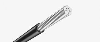
Structurally, SIP consists of aluminum cores twisted together and protected by a durable layer of polyethylene. The conductors are light-stabilizing, therefore, when exposed to ultraviolet rays, their technical and operational characteristics do not change.
The shell of individual conductors in SIP is black. The cable includes a load-bearing element connected to the zero. The rest of the wires are wound around it.
In general, SIP consists of the following components:
- current-carrying conductors;
- steel wire core;
- high-strength polyethylene shell.
The SIP-3 power cable is made of aluminum conductors and a steel core with a round cross-section. The number of cores is formed in accordance with the standards of specifications individually for the selected brand. The design of SIP may imply the use of a self-supporting aluminum core; in SIP-3, SIP-4 and SIP-5 it is absent.
Important! The quality of the SIP can be judged by how the phase wire is twisted. It always moves clockwise relative to zero.
In the electric cable SIP-2, SIP-3 or SIP-5, the sheath is made of cross-linked XLPE, which increases light stabilization. In SIP-1 and SIP-4 it is made from thermoplastic polyethylene (LDPE).
The technical parameters of the product depend on its design features. One or two capital letters placed in brackets can be added to the abbreviation SIP:
- SIP (N) – the shell of the conductors is made from materials that are resistant to combustion.
- SIP (G) - insulation protects the wire structure from exposure to water or moisture.
- SIP (NG) - cross-linked polyethylene is used for the shell, resistant to both combustion and moisture penetration.
Design
|
Structural and electrical parameters
| Number and cross-section of cores, pcs. x sq.mm | Estimated weight, kg/km | Diameter, mm | Permissible current load, A | One-second short circuit current, kA | |
| with aluminum alloy core | with aluminum core, reinforced with steel wire | ||||
| 1x16 + 1x25 | 167,2 | 188,5 | 15,0 | 105 | 1,5 |
| 2x16 | — | 131,9 | 14,0 | 100 | 1,5 |
| 2x25 | — | 197,9 | 17,0 | 130 | 2,3 |
| 3x16 + 1x25 | 299,2 | 320,4 | 22,0 | 100 | 1,5 |
| 4x16 + 1x25 | 365,1 | 386,3 | 26,0 | 100 | 1,5 |
| 4x16 | — | 263,8 | 22,0 | 100 | 1,5 |
| 3x25 + 1x35 | 429,2 | 462,5 | 26,0 | 130 | 2,3 |
| 4x25 + 1x35 | 527,7 | 561,1 | 26,0 | 130 | 2,3 |
| 4x25 | — | 394,3 | 26,0 | 130 | 3,2 |
| 3x25 + 1x54.6 | 505,6 | — | 26,6 | 130 | 2,3 |
| 3x35 + 1x50 | 577,5 | 620,6 | 30 | 160 | 3,2 |
| 3x35 + 1x54.6 | 599,6 | — | 28,4 | 160 | 3,2 |
| 3x50 + 1x50 | 736,3 | 779,3 | 32 | 195 | 4,6 |
| 3x50 + 1x54.6 | 758,3 | — | 32,8 | 195 | 4,6 |
| 3x50 + 1x70 | 799,8 | 862,4 | 35,0 | 195 | 4,6 |
| 3x70 + 1x54.6 | 944,2 | — | 36 | 240 | 6,5 |
| 3x70 + 1x70 | 985,7 | 1048,3 | 37,0 | 240 | 6,5 |
| 3x70 + 1x95 | 1073,6 | 1160,3 | 41,0 | 240 | 6,5 |
| 3x95 + 1x70 | 1242,7 | 1305,3 | 41 | 300 | 8,8 |
| 3x95 + 1x95 | 1330,6 | 1417,3 | 45,0 | 300 | 8,8 |
| 3x120 + 1x95 | 1556,8 | 1643,5 | 47,0 | 340 | 7,2 |
Advantages and technical characteristics of SIP cables
GOST requirements establish the following parameters for SIP brand products:
- The insulating shell, which is made from polyethylene materials, must be resistant to sunlight and not be destroyed under its influence, since, as a rule, these products are used in areas where no shelter from the sun, wind or precipitation is provided;
- During installation, the bending radius should not be less than 10 wire diameters. Thus, the product is subject to requirements not only for strength, but also for flexibility, because the network sometimes has to be laid in difficult territorial conditions (in the mountains, past forests, and so on);
- The period of stable operation without replacement must be at least 40 years, which also places high demands on the technical characteristics of the wire;
- The manufacturer is obliged to establish a warranty period of at least three years;
- Each core in the cable must be marked.
Comparative table of parameters of various types of products
CharacteristicsSIP 1SIP 2SIP 3SIP 4
| Cross section of one core, mm | From 16 to 120 | From 16 to 120 | From 32 to 240 | From 16 to 120 |
| Number of cores in one wire, pcs. | From 1 to 4 | From 1 to 4 | 1 | From 2 to 4 |
| What is the neutral core made of? | Steel core with aluminum alloy wire wrapping | Steel core with aluminum alloy wire wrapping | Zero core missing | Zero core missing |
| What is the phase cable made of? | Aluminum | Aluminum | Steel core with aluminum alloy wire wrapping | Aluminum |
| Voltage at which the wire is operated, kV | From 0.4 to 1 | From 0.4 to 1 | From 10 to 35 | From 0.4 to 1 |
| What is insulation made of? | Thermoplastic polyethylene | Light-resistant polyethylene | Light-resistant polyethylene | Thermoplastic polyethylene |
| Maximum overheating temperature, degrees Celsius | 70 | 90 | 70 | 90 |
Based on the technical characteristics of the cable being described, the following advantages can be identified:
- Affordable price, which can significantly reduce the cost of network installation. In the future, this will have a positive impact on the cost of connecting industrial enterprises or housing to energy supply facilities;
Parameters of different types of wires
- The design of the wire ensures stable operation of the high-voltage power transmission line due to the absence of cable breaks or contact with each other as a result of gusts of wind, which often causes a short circuit and emergency shutdown of power supply;
- It is possible to maintain power lines without interrupting the supply of electric current. This is achieved through durable and high-quality insulation;
- Thanks to the use of special puncture technology, it is possible to connect new energy consumers without stopping the operation of the feeder, which allows reducing connection time while complying with all safety requirements;
- All cores are completely insulated, which practically eliminates the possibility of a short circuit and allows one to significantly reduce the security zone, which means it creates additional opportunities for the development of the adjacent territory and increases its economic potential;
- The light weight of the product allows you to install up to four circuits on one support, which reduces the cost of laying a power line;
Additional Information. This circumstance allows the use of lightweight fittings during installation, which again has a positive effect on the cost of laying power lines. If possible and compliance with safety requirements, the line can even be laid along the facades of buildings and fences.
- The wire described is very easy to maintain (cable inserts are quite simple if you have the appropriate devices); you just need to have the appropriate approval. In addition, the use of puncture technology when connecting new consumers practically does not damage the cable itself, while ensuring a stable power supply;
Important! Due to the design features and reliability of the insulation, the use of SIP cable allows us to minimize energy losses during its transmission. And this parameter is one of the key ones for energy supply companies when choosing materials.
- Resistance to aggressive environmental influences (temperature changes, gusts of wind, increased levels of precipitation, and so on). In addition, due to the strength of the insulation and the wire itself, it is possible to install anti-snow and anti-icing devices on it.
Advantages of the wire
Thus, the SIP cable, thanks to its design and the materials used in production, can significantly reduce construction time, optimize operating costs and ensure a stable supply of electricity to connected objects in almost any climatic conditions.
In addition, it fully complies with all safety requirements, and its use significantly reduces the likelihood of a short circuit, fire or electric shock.
Specifications
| Parameter | Meaning |
| Rated alternating voltage frequency 50 Hz, kV | 1,0 |
| Operating temperature of the core, no more than °C | 90 |
| Core temperature in overload mode for 8 hours, no more than °C | +130 |
| Short circuit temperature for 5 seconds, no more than °C | +250 |
| Ambient temperature, min./max., °C | -50/+50 |
| Installation at a temperature not lower than °C | -20 |
| Service life, years | 25 |
| Warranty period, years | 3 |
Resistance of current-carrying conductors, no more, Ohm/km
| cross section, sq.mm | phase | carriers |
| 16 | 1,91 | — |
| 25 | 1,20 | 1,38 |
| 35 | 0,868 | 0,986 |
| 50 | 0,641 | 0,720 |
| 54,6 | — | 0,630 |
| 70 | 0,443 | 0,493 |
| 95 | 0,320 | 0,363 |
| 120 | 0,253 | 0,288 |
| 150 | — | 0,236 |
Tensile strength of load-bearing cores, not less, kN
| cross section, sq.mm | carriers |
| 25 | 7,4 |
| 35 | 10,3 |
| 50 | 14,2 |
| 54,6 | 16,6 |
| 70 | 20,6 |
| 95 | 27,9 |
| 120 | 35,2 |
| 150 | 43,4 |
Advantages of SIP
- With equal capital investments, power lines with self-supporting insulated wires require lower operating costs;
- Reducing the width of clearings to be cut down during the construction of power lines in forest areas;
- Possibility of joint suspension on supports of wires with different voltage levels and with telephone lines;
- The possibility of installing power lines along the facades of buildings, which can eliminate the installation of some of the supports that clutter the sidewalks, it is possible to lay a completely or partially hidden network, making it easier to connect branches to buildings;
- Reducing safe distances to buildings and other engineering structures (electrical, telephone, overhead lines);
- Height above ground level - 4 meters, for bare wires - 6 meters;
- The possibility of a short circuit between phase wires or to ground is excluded;
- Eliminating the risk of fires if wires fall to the ground;
- High service safety - no risk of injury when touching live phase wires;
- Less weight and longer duration of snow sticking, increased reliability in areas of intense ice formation, reduction of ice and wind loads on supports;
- Reduced voltage drop due to low reactance;
- Reducing the volume of emergency recovery work;
- Ease of repair, especially when working under voltage;
- Reducing the likelihood of electricity theft and destruction of power lines;
- Safety of work near power lines.
At the customer's request, SIP-2A wire can be supplied with additional insulated conductors with a cross-section of 16 or 25 mm2 for connecting lighting circuits.
Types and purpose of SIP wires
SIP wire is the best option for running power lines to a private home. This is an inexpensive product with good technical and operational characteristics, which is available in three varieties:
- exposed carrier neutral;
- isolated carrier neutral;
- self-supporting cable.
The main material for the manufacture of current-carrying cores and supporting conductors is aluminum. In the latter case, an alloy with high load-bearing capacity is used. Let's look at the main types of SIP.
Wire SIP-1
In this case, the wire is manufactured with a bare carrier neutral in accordance with the European standard. Structurally, SIP-1 is one load-bearing bare wire made of pure aluminum or a reinforced alloy, around which one to four current-carrying conductors with LDPE insulation are twisted. The latter material protects the product from ultraviolet rays.
This wire is used during the installation of main electrical transmission lines and various branches, provided there is dry or normal air with a minimum amount of dust. Suitable for electrical networks with a total voltage of 600 or 1000 V at a frequency of 50 Hz.
All conductors, protected by insulation, are twisted around the supporting wire with a certain pitch. An individual core may consist of one or more wires. The neutral core is made from a high-quality core. Steel or aluminum can be used. Round aluminum conductors are placed around the core. The diameter of the supporting core is much larger.
After laying the SIP, the weight of the entire structure is restrained by the load-bearing core installed on guy wires, attached to poles, etc. This is associated with an increase in thickness relative to other current-carrying conductors. In most cases, the thickened core is zero. The remaining cores are necessarily insulated with thermoplastic polyethylene, capable of withstanding air temperatures up to 70 degrees. Celsius with continuous heating or up to 125 degrees. Celsius at short-term. Also, the power line at SIP-1 will withstand heavy snow loads.
The main disadvantage of using SIP-1 is that when a phase imbalance occurs, a high and life-threatening voltage may appear on the exposed supporting wire. To prevent this, the neutral at each pole is grounded. But even if there is such a possibility, it is not recommended to lay street cable along the facade of the building.
Wires SIP-2 and SIP-3
Wires of brands SIP-2 and SIP-3 have an insulated neutral. The supporting neutral wire, unlike SIP-1, is protected by a high-quality sheath, while the remaining structural elements remain unchanged: one to four current-carrying conductors are twisted around the thickened neutral, insulated with cross-linked polyethylene with high light-stabilizing properties.
Operation of SIP-2 is permissible in electrical networks with a voltage of 600 or 1000 V. Unlike SIP-1, the second category can be used in conditions of high humidity and high salt content in the air (for example, on the coast of seas and oceans, near salt marshes, etc. .). The wire can also be fixed directly to the walls of residential buildings. This is an ideal solution when laying lines from a pole to a house.
SIP-3 is identical in structure to the cable of the second category, but is characterized by a thicker sheath. Thanks to this, the prefix “protected” is added to the description of the wire. Operation is permissible in networks with a much higher rated voltage - up to 20 or 35 kV, depending on the specific product model. As for technical characteristics, the cable is identical to SIP-1, although differences can be found when comparing permissible current loads.
SIPs of the second and third categories are suspended on a supporting conductor of increased diameter. Since it is insulated, possible current induction is eliminated. However, there is a risk of shell rupture due to excessively high mechanical stress. Thus, when designing a power transmission line on SIP-2, installers try to reduce the span (the distance between the nearest poles) to a minimum.
Wire SIP-4, SIP-5 and SIP-7
In design, all three categories of wires differ significantly from those listed above:
- the product does not have a supporting conductor, so the load is immediately placed on all current-carrying conductors;
- the strength of the cable is much lower than SIP-1, SIP-2 and SIP-3, which is precisely due to the lack of a support wire;
- they cannot be used in regions with large amounts of precipitation in the form of snow or frequent icing.
It is also worth noting that the wire can consist of two, three or four conductors (there are no single-core SIPs of the fourth, fifth or seventh categories). One or two wires for lighting can be added to the product. The veins twist together to form a common center. The twist pitch depends on the specific model. One core is made zero, all the rest are made phase.
SIP-4 is used in electrical networks with a voltage of 600 or 1000 V. Since the design does not imply the use of a thickened load-bearing core, the cable is characterized by increased flexibility, and the minimum bending radius is 7.5 radii of the total diameter.
This is the most popular SIP wire, due to its reduced cost and good technical parameters. There are several additional types of SIP of the fourth category:
- SIPn-4 is manufactured with high-quality insulation that does not support combustion.
- SIPsn-4 has non-flammable insulation and one or two lighting conductors. It can also be upgraded with one to three copper conductors for control circuits. In this case, numbers are added to the abbreviation through a “plus” indicating the number of these auxiliary conductors.
- The SIPgsn-4 cable differs from the previous version in that it can additionally prevent moisture from entering.
The last two types of wire have a European analogue called AsXSn. The purpose and most technical and operational characteristics of these products are identical.
The next category - SIP-5 - differs from the previous one in that it is not possible to turn on auxiliary conductors for signaling or lighting. The product contains current-carrying conductors of identical diameters. The total number of conductors is from two to four: as always, one of them is neutral, the rest are phase.
Single-core wire SIP-7 is produced with reinforced insulation, consisting of several layers:
- screen made of electrically conductive polyethylene;
- cross-linked polyethylene;
- weather-resistant polyethylene.
This cable can be used in electrical networks whose voltage reaches 110 kV. An excellent option in cases where it is not possible to carry out underground electrical installations, and the use of bare conductors is unacceptable. The most striking example is park areas and other high-traffic areas. SIP-7 is suitable for use in temperate, cold or tropical climates. Less common is copper insulated cable SIP-7.
Application area
Self-supporting insulated wires (SIP) are intended for use in overhead power lines (power lines) suspended on supports or facades of buildings and structures.
Climatic modification - UHL, placement categories - 1, 2 and 3, in atmospheres of type II and III according to GOST 15150-69.
As a result of generalizing domestic experience in the construction and operation in a number of regions of the country of overhead power lines with a voltage of 0.38 kV with self-supporting insulated wires, the technical and economic advantages of these lines were revealed in comparison with overhead power lines of 0.38 kV with uninsulated wires.
Based on the positive experience of using self-supporting insulated wires in power systems, the RAO UES of Russia directive document No. OB-5145 dated June 26, 2000 “On the use of self-supporting insulated wires in construction and reconstruction” was issued.
Areas of use
The materials from which it is made, the design features, and therefore the scope of application depend on the brand of the product. In particular:
- SIP 1 wire is most often used in the construction of power lines and inputs into buildings;
- SIP 2 cables are also used for laying power lines and power supply to buildings. Their key feature is the type of atmospheric design, which allows them to be installed in places with high humidity, for example, on the shores of seas, lakes, in areas with poor environmental conditions and harsh climatic conditions, since their insulation is resistant to aggressive environmental influences;
- Products with the SIP 3 brand are used for laying sections of power lines with voltages from 10 to 35 kV. In addition, such a wire is used to connect equipment operating under high voltage. This is due to the cable design, which is able to withstand high-level loads;
- SIP 4 wires are used primarily for arranging various branches, since they have a higher level of flexibility. They are also distinguished by their frost resistance, which allows them to be used when laying power lines in the Far North;
- SIP 5 cable is used almost exclusively for installing branches.
Use of SIP brand products
So, the SIP cable, the decoding of which means that it is self-supporting (it has both phase and neutral wires) and insulated, is intended for laying power supply lines and branches from it. The operating voltage under which this product can be operated ranges from 0.4 to 1 kV, but for some brands it can reach 35 kV.
The main advantages of the described products are ease of maintenance and low weight, which can significantly reduce costs when laying power lines. At the same time, it meets all requirements regarding the safety and stability of energy supply.
Advantages and disadvantages
Let us list the main advantages of SIP wires:
- Easy to install and lay. The process takes less effort and time compared to installing other bare wires. There is no need to attach the conductors to insulators.
- Reducing the likelihood of unauthorized connection to the line. Switching requires certain skills and work experience, so not everyone can perform such actions.
- SIP insulating shells are made from high-quality material that repels wet snow and condensation, which eliminates serious icing of the line. If ice appears, it is in small quantities.
- Reducing the likelihood of electric shock. The presence of conductor insulation reduces the risk of electric shock during repair work and maintenance of power lines. Many operations can be performed without turning off the voltage.
- Economical. Due to the SIP design, the wire is less susceptible to breakage. Minimal funds are spent on maintenance; the wire can be installed on the facades of residential buildings (with the exception of some categories), thereby reducing the number of installed supports.
- Reduced inductance. Due to the low reactance in the wire, the amount of power and voltage losses is significantly less. This eliminates the formation of current pickups and allows you to mount self-supporting insulated insulated wires on supports for low-voltage lines.
The disadvantages include:
- High cost compared to simple bare wires. For quite objective reasons, the price of SIP is significantly higher than the cost of conventional non-insulated cables.
- When using SIP, you must contact qualified specialists. Only they can perform high-quality installation and maintenance of power lines using these wires. This is due to the fact that such products appeared relatively recently, so they have not yet become so widespread. Add to all this the fact that domestic electrical supply systems are not suitable for the transition to self-supporting insulated conductors.
Cable connection
When the cable tracks are laid, you need to connect the power network, which is the source of electricity for subscribers. At the same time, we must not forget the following:
- The connection to wires without an insulating coating is made through sleeves with a hermetic compound, to the rest - through tight clamps. In this case, the insulation is removed from the tip of the cable, then the elements are compressed with a press.
- Branch clamps can be used for communication. They are suitable for conductors without a supporting core, in which other current-carrying components are secured in the clamp with a steel clamp.
Selecting a section and checking the product
When going to the store to purchase a self-supporting insulated wire, pay attention to the rated current. To calculate the required value, a diagram is formed that takes into account the length of the power network sections and the load on each of them.
After you calculate the approximate current value, compare it with the one indicated in the table below to select the SIP brand and cross-sectional size. Table of SIP cross-sections depending on permissible currents:
| Core cross-section, sq. mm | Permissible current for LPDE insulation | Permissible current for XLPE insulation |
| 16 | 70 | 100 |
| 25 | 95 | 130 |
| 35 | 115 | 160 |
| 50 | 140 | 195 |
| 70 | 180 | 240 |
| 95 | 220 | 290 |
| 120 | 250 | 340 |
For example, if the calculated current is 110 A, then you need to purchase SIP-1 with a cross-section of 35 square meters. mm or SIP-2 with a cross section of 25 sq. mm. The latter option is preferable, since such a wire will be lighter, stronger and more protected from wind and precipitation.
Advice! When choosing SIP, try to buy a wire with current-carrying conductors of a larger diameter than required according to the calculation. This will cover any load increases that occur in the future.
Before installing the wire, make sure that all wires are intact. To do this, use a multimeter:
- Switch the toggle switch to the “Test” position of the resistance sector, then connect the red and black probes to each other. If the device is working properly, you will hear a signal indicating that the dialing mode is activated.
- Using two probes, touch both ends of the SIP wire. If there is no damage to the conductor, you will hear a beep indicating that the charge has passed from one end to the other.
- These steps will need to be repeated for each core.
Similar checks should be carried out for a toggle switch installed in the resistance measurement sector from 200 Ohm to 200 kOhm. If the display shows “0”, then the conductor is intact, “1” - there is a break in the line.
Test after installation
The rules for accepting overhead lines are described in the standards for distribution networks with a voltage of 380-20,000 volts. It is necessary to measure the resistance of the core insulation using a megger, sharpened to work with a voltage of 1 kilovolt. Measure data between zero and each phase. Also, all phases are paired with each other and with the lighting line.
If in one of the measurements the indicator exceeds 0.5 MOhm, an insulation breakdown may be suspected. Using a similar 2.5 kilovolt device, you can check the quality of the insulation. The same pairs of cores are tested. If the layer is not damaged, it is considered reliable.
This SIP series cable is well suited for arranging transmission lines. The availability of installation options that do not require the installation of additional supports allows you to save resources.
Manufacturers and cost of SIP cables
There are a huge number of factories and small manufacturers producing various brands of SIP cable. The companies listed below mostly produce high-quality products in accordance with the stated requirements:
- Kamsky Kabel LLC;
- LLC "GK Sevkabel";
- JSC "Moskabel Plant"
The cost of the product depends on the specific manufacturer and category of wire. For example, SIP-1 can be purchased on average for 20, SIP-2 – 25, SIP-3 – 60, SIP-4 – 100 rubles/p. m. The indicated prices may vary depending on the selected region of our country.
Specifications
The cross-section of the conductors of SIP wires ranges from 16 to 185 mm2, is capable of powering powerful consumers and passing currents up to 500 A, and permissible currents of one-second short circuits can reach 16 kA. There is a large selection of cable options in terms of cross-sectional dimensions and permissible current, so this wire is universal for constructing overhead lines.
The operating temperature ranges from -60 to +50 °C, and the cable design can be for both moderate and cold climates. Installation of SIP wire is possible at temperatures down to -20 °C.
The service life reaches 45 years and most manufacturers provide a warranty of up to 5 years.
Such a cable is subject to mechanical loads from wind, ice, and snow, so such lines must be calculated based on their weight and the effect of mechanical loads on them. For this calculation, data on the destructive force of the supporting cable are used, depending on the type, cross-section and mass of the wire.
Packaging, storage and transportation of SIP products
In accordance with GOST, self-supporting insulated wire is supplied in drums. The product can only be transported in them. Sometimes transportation with subsequent storage in bays is possible. In this case, two conditions must be met: the cross-section of the core must be 16-25 square meters. mm, the total weight of the coil is up to 25 kg. When storing, use sheds or closed areas. Short-term outdoor accommodation is possible.
According to standards, the outer surface of the drums must be protected with special mats. An accompanying document in the form of a label or technical passport must be added to the product. It is attached to the drum cheek or bay. To prevent the label or passport from getting lost, it should be placed inside a moisture-proof package.
Thus, the SIP wire discussed in the article has practically no disadvantages. If you find a qualified installer, regardless of the slightly inflated cost, then there will be no disadvantages at all. Keep in mind that the costs will soon pay for themselves due to the absence of voltage and power losses, protection against unauthorized switching leading to the theft of electrical energy, and savings in the maintenance of power lines.
Advantages of the cable
Compared to bare wires, SIP has a number of advantages: it is resistant to various weather factors, has a minimal probability of short circuits when the wires come into contact with each other or other objects, and is safe for people.
During the production process, wires undergo a number of tests simulating various situations that may arise during operation, which ensures their reliable operation throughout their entire service life.
Wire structure
The cores have a round shape; in the finished wire they are twisted together in increments of 80 to 150 cm, depending on their cross-section. Current-carrying conductors are made of both aluminum and its alloys (in the case of SIP-3), load-bearing conductors are made exclusively of aluminum alloys. For cross-sections up to 95 mm2, the core consists of 7 wires, for the rest - from 19. A wire with a cross-section of 95 mm2 can be made in both versions.
The load-bearing core has a strength on average 2-2.5 times greater than a current-carrying core of the same cross-section. For aluminum wire, the tensile strength is set to at least 120 N/mm2; for wire made from aluminum alloys, this figure is significantly higher - at least 295 N/mm2.
The insulation of the wires allows them to be resistant to ultraviolet radiation, both very low and high temperatures, as well as precipitation, including protection from snow and icing. The insulation material is cross-linked light-stabilized black polyethylene.
Diversion of SIP from overhead lines to the house
In order to connect a SIP wire from a pole to a house, you need to accurately measure the distance to the nearest support. If it exceeds 25 meters, you will have to install an additional power pole - perhaps right in the yard.
Maximum distance to the nearest pole Source fs137.myvi.tv
If the standard is met, you can lay the wire directly from the street support. Let's figure out what is needed for this.
Required fittings
To carry out installation work, the following fittings are required:
Branch (piercing) clamp with protective cap Source static-eu.insales.ru
- The number of clamps corresponds to the number of current-carrying cores of the wire.
Anchor clamp Source must.su
- To install a SIP cable from a pole to a house, you need 2 clamps, and two more for an additional branch support, if one is installed.
Steel fastening tape (bandage) Source kvt-pro.ru
- A galvanized steel tape is used to secure the SIP to the power line pole. One support requires 1 meter of tape.
Book clip Source infoyar.ru
- Reinforced clamps (buckles) are used to fix the steel bandage. There are 2 pieces per bracket.
Bracket Source dixi-st.com
See also: Catalog of flat roof house projects
- To secure the branch wire to the support, you will need 2 or 4 brackets. They are attached to the pole with tape, and to the facade of the building with anchors.
Strap (tightening clamp) Source svetelektro.net
- It takes 5 straps to make one connection.
Fastening Source stofasadov.ru
- Fastening SIP to the wall of a building is carried out using this simple device. Installed at 70 cm intervals, so the quantity is calculated based on the total length of the input.
Process in action
Now let’s illustrate how all this comes together into a single structure.
Installing anchors and pulling wires
It is impossible to drill an electrical support, so to install the brackets, not anchor bolts are used here, but bandage tape. It is wrapped in two rows around the post and secured with paper clips (buckles).
Attaching the bracket to the pole using tape Source youtube.com
- Then the wedge, which is shown in the photo with a red arrow, is removed from the anchor clamp, the wire is pulled through it and the wedge is inserted back.
Pulling the wire through the anchor clamp Source youtube.com
- Now, using the clamp fork, the wire is fixed to the bracket.
Installation of SIP on supports using an anchor clamp Source youtube.com
See also: Catalog of companies that specialize in electrical work and related services
- To connect to an overhead line, you need to install branch clamps with one side on the main wire, and the other on the wire that will go to the house. The arrow in the picture shows the central bolt. It must be tightened with a spanner until it comes off.
Installation of branch clamps Source youtube.com
- Protective caps are put on the exposed ends of the wires, and the wire strands are tightened with a clamp.
Wire lugs Source youtube.com
- The wire is thrown towards the house, where a bracket is also installed to secure it. Only here it will be fixed not with a bandage, but with bolts.
Mounting the bracket to the facade Source youtube.com
Note! The height of the wire to the building according to SNiP is 2.75 m, but if the house itself does not meet this parameter, the entry can be made through the roof.
The type of anchors for installation on the facade is selected based on the wall material. After securing the bracket, an anchor clamp with a wire threaded into it is attached to its eye in the same way as was done at the opposite end. The clamp must be installed so that the wire between the pole and the wall of the house is tensioned and not sagging.
Attaching the wire to the facade Source youtube.com
Important! The wire is tensioned using a hand winch, which has a mechanism for capturing and compressing the load-bearing core or the entire bundle. The force applied to the wire must be accurately measured, for which a dynamometer is used. If work is carried out according to a project, then data on the tension force is taken from it. In the absence of regulatory documentation, the amount of force that must correspond to the cable brand and its span between the anchors can be taken from the installation table.
If the distance of the nearest VLI pole to your house was more than 25 meters and you had to install an intermediate support, the wire will be attached to it as shown in the picture below.
Attaching SIP to an intermediate support Source youtube.com
Cable designation
KG cable - decoding and technical characteristics
According to GOST, the marking of conductors should look like:
- The first symbols are “SIP”, indicating the type of conductor;
- The numbers from 1 to 4 are indicated with a hyphen;
- At intervals, numbers are added that indicate the number of each type of core, then through the multiplication sign - their cross-section. Numbers related to each type are separated from each other by a “+” sign;
- A dash indicates the rated voltage of the cable;
- Technical specifications may also be indicated at intervals.
For example, if the marking SIP-2 3×70 + 1×95 + 2×25 - 0.6/1 TU is indicated, then the parameters of the self-supporting insulated wire are as follows:
- designed for organizing overhead power lines;
- has veins:
- 3 main sections 70mm2;
- 1 insulated carrier with a cross-section of 95mm2;
- 2 auxiliary sections 25mm2.
- The cable is designed for voltage 0.6/1 kV.
Accessories for working with self-supporting insulating wires
Additional accessories are used for operation:
- piercing clamp;
- support clamp;
- brackets and brackets for poles;
- load-bearing core tensioner;
- wedge clamp, etc.
Installation of power lines using a piercing clamp
The use of SIP cables allows you to quickly and efficiently install the electrical network.
