The author of the article is a professional tutor, author of textbooks for preparing for the Unified State Exam Igor Vyacheslavovich Yakovlev
Topics of the Unified State Examination codifier: alternating current, forced electromagnetic oscillations.
Alternating current
- these are forced electromagnetic oscillations caused in an electrical circuit by a source of alternating (most often sinusoidal) voltage.
Alternating current is present everywhere. It flows through the wires of our apartments, in industrial electrical networks, and in high-voltage power lines. And if you need direct current to charge your phone or laptop battery, you use a special adapter that rectifies the alternating current from the outlet.
Why is alternating current so widespread? It turns out that it is easy to obtain and ideally suited for transmitting electricity over long distances. We will talk about this in more detail in the leaflet devoted to the production, transmission and consumption of electrical energy.
Now we will look at the simplest AC circuits. We will connect to the AC voltage source one by one: a resistor with a resistance, a capacitor with a capacitance and an inductor. Having studied the behavior of these elements, we in the next sheet “Alternating Current. 2" let's connect them simultaneously and examine the passage of alternating current through an oscillatory circuit with resistance.
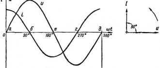
The voltage at the source terminals varies according to the law:
(1)
As you can see, voltage can be positive and negative. What is the meaning of the voltage sign?
It is always assumed that the positive direction of the circuit traversal is selected. Voltage is considered positive if the electric field of the charges forming the current is in a positive direction. Otherwise the voltage is considered negative
.
The initial voltage phase does not play any role, since we are considering processes that are established over time. If desired, instead of the sine in expression (1), one could take the cosine - nothing would fundamentally change.
The current voltage value at a time is called the instantaneous voltage value
.
Alternating electric current
In a mechanical system, forced vibrations occur when an external periodic force acts on it. Similarly, forced electromagnetic oscillations in an electrical circuit occur under the influence of an external periodically varying EMF or an externally varying voltage.
Forced electromagnetic oscillations in an electrical circuit represent alternating electric current
.
- Alternating electric current
is a current whose strength and direction periodically change.
In the future, we will study forced electrical oscillations that occur in circuits under the influence of voltage that varies harmoniously with frequency ω
according to the sinusoidal or cosine law:
\(~u = U_m \cdot \sin \omega t\) or \(~u = U_m \cdot \cos \omega t\) ,
where u
– instantaneous voltage value,
U
m – voltage amplitude, ω – cyclic oscillation frequency.
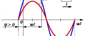
If the voltage changes with a frequency ω, then the current in the circuit will change with the same frequency, but the current fluctuations do not necessarily have to be in phase with the voltage fluctuations. Therefore, in the general case \(~i = I_m \cdot \sin (\omega t + \varphi_c)\),
where φc is the phase difference (shift) between the current and voltage fluctuations.
Based on this, we can give the following definition:
- Alternating current
is an electric current that changes over time according to a harmonic law.
Alternating current ensures the operation of electric motors in machines in plants and factories, powers lighting fixtures in our apartments and outdoors, refrigerators and vacuum cleaners, heating appliances, etc. The frequency of voltage fluctuations in the network is 50 Hz. The alternating current has the same oscillation frequency. This means that within 1 s the current will change its direction 50 times. A frequency of 50 Hz is accepted for industrial current in many countries around the world. In the USA, the frequency of industrial current is 60 Hz.
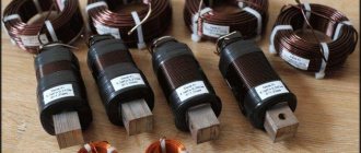
Origin of inductive reactance
There is a magnetic field around a conductor with moving charged particles. It is weak, but the magnetic needle reacts to it.
If a conductor is wound around a coil, the magnetic field will become much stronger. This leads to the appearance of another type of current in the coil. Its occurrence in a conductor under the influence of a magnetic field is called electromagnetic induction. The winding is called an inductance coil, and the movement of charges is called an induction current.
One of the manifestations of electromagnetic induction is self-induction: the occurrence of additional EMF at moments of sudden changes in current strength.
These are not oscillations excited by the generator, but changes at the moment of switching on, switching off, or short circuit. The following formula is valid for the phenomenon:
Esi = -L(ΔI/Δt).
Designations:
- Esi – self-induced emf;
- ΔI – change in current strength;
- Δt – time period;
- L – coil inductance, self-inductance coefficient.
The L value is a characteristic of the magnetic properties of the coil; it is measured in henry (H).
The inductance of the coil is 1 H if, when the value of I in it changes by 1 A in 1 second, a self-inductive emf of 1 V occurs.
Alternator
The bulk of the world's electricity is currently generated by alternating current generators, which create harmonic oscillations.
- An alternating current generator
is an electrical device designed to convert mechanical energy into alternating current energy.
The induction emf of the generator changes according to a sinusoidal law
\(e={\rm E}_{m} \cdot \sin \omega \cdot t,\)
where \({\rm E}_{m} =B\cdot S\cdot \omega\) is the amplitude (maximum) value of the EMF. When connected to the terminals of the load frame with resistance R
, alternating current will pass through it. According to Ohm's law for a section of a circuit, the current in the load
\(i=\dfrac{e}{R} =\dfrac{B \cdot S \cdot \omega }{R} \cdot \sin \omega \cdot t = I_{m} \cdot \sin \omega \cdot t,\)
where \(I_{m} = \dfrac{B\cdot S\cdot \omega }{R}\) is the amplitude value of the current.
The main parts of the generator are (Fig. 1):
- inductor
- an electromagnet or permanent magnet that creates a magnetic field; - armature
- a winding in which an alternating EMF is induced; - a commutator with brushes
is a device by which current is removed from or supplied to rotating parts.
Rice.
1 The stationary part of the generator is called the stator
, and the movable one is
the rotor
. Depending on the design of the generator, its armature can be either a rotor or a stator. When receiving high-power alternating currents, the armature is usually made motionless in order to simplify the current transmission circuit to the industrial network.
In modern hydroelectric power plants, water rotates the shaft of an electric generator at a frequency of 1-2 revolutions per second. Thus, if the generator armature had only one frame (winding), then an alternating current with a frequency of 1-2 Hz would be obtained. Therefore, to obtain alternating current with an industrial frequency of 50 Hz, the armature must contain several windings that allow increasing the frequency of the generated current. For steam turbines, the rotor of which rotates very quickly, an armature with one winding is used. In this case, the rotor rotation frequency coincides with the alternating current frequency, i.e. the rotor should make 50 rps.
Powerful generators produce a voltage of 15-20 kV and have an efficiency of 97-98%.
From the history
. Initially, Faraday detected only a barely noticeable current in the coil when a magnet moved near it. "What's the use of this?" - they asked him. Faraday replied: “What use can a newborn baby have?” A little more than half a century has passed and, as the American physicist R. Feynman said, “the useless newborn turned into a miracle hero and changed the face of the Earth in a way that his proud father could not even imagine.”
*Operating principle
The operating principle of an alternating current generator is based on the phenomenon of electromagnetic induction.
Let a conducting frame of area S
rotates with an angular velocity ω around an axis located in its plane perpendicular to a uniform magnetic field with induction \(\vec{B}\) (see Fig. 1).
With uniform rotation of the frame, the angle α between the directions of the magnetic field induction vector \(\vec{B}\) and the normal to the plane of the frame \(\vec{n}\) changes with time according to a linear law. If at time t
= 0 angle α0 = 0 (see Fig. 1), then
\(\alpha = \omega \cdot t = 2\pi \cdot \nu \cdot t,\)
where ω is the angular velocity of rotation of the frame, ν is the frequency of its rotation.
In this case, the magnetic flux passing through the frame will change as follows
\(\Phi \left(t\right)=B\cdot S\cdot \cos \alpha =B\cdot S\cdot \cos \omega \cdot t.\)
Then, according to Faraday's law, an induced emf is induced
\(e=-\Phi '(t)=B\cdot S\cdot \omega \cdot \sin \omega \cdot t = {\rm E}_{m} \cdot \sin \omega \cdot t.\ )
We emphasize that the current in the circuit flows in one direction during half a turn of the frame, and then changes direction to the opposite, which also remains unchanged during the next half turn.
RMS values of current and voltage
Let the current source create an alternating harmonic voltage
\(u=U_{m} \cdot \sin \omega \cdot t.\;\;\;(1)\)
According to Ohm's law, the current in a section of a circuit containing only a resistor with a resistance R
, connected to this source, also changes with time according to a sinusoidal law:
\(i = \dfrac{u}{R} =\dfrac{U_{m} }{R} \cdot \sin \omega \cdot t = I_{m} \cdot \sin \omega \cdot t,\; \;\; (2)\)
where \(I_m = \dfrac{U_{m}}{R}.\) As we see, the current strength in such a circuit also changes over time according to a sinusoidal law. Quantities Um
,
Im
are called
the amplitude values of voltage and current
.
The time-dependent values of voltage u
and current
i
are called
instantaneous
.
In addition to these quantities, another characteristic of alternating current is used: effective (effective) values of current and voltage
.
- The effective (effective) value of an
alternating current is the strength of a direct current that, passing through a circuit, releases the same amount of heat per unit time as a given alternating current.
Denoted by the letter I
.
- The effective (effective) value of an
alternating current voltage is the voltage of a direct current that, passing through a circuit, releases the same amount of heat per unit time as a given alternating current.
Denoted by the letter U
.
Active ( I, U
) and amplitude (
Im, Um
) values are related to each other by the following relationships:
\(I = \dfrac{I_{m} }{\sqrt{2}}, \; \; \; U =\dfrac{U_{m} }{\sqrt{2}}.\)
Thus, the expressions for calculating the power consumed in direct current circuits remain valid for alternating current if we use the effective values of current and voltage in them:
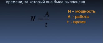
\(P = U\cdot I = I^{2} \cdot R = \dfrac{U^{2}}{R}.\)
It should be noted that Ohm's law for an alternating current circuit containing only a resistor with a resistance R
, is carried out both for amplitude and effective, and for instantaneous values of voltage and current, due to the fact that their oscillations coincide in phase.
\(I=\dfrac{U}{R}.\;\;\;(3)\)
*Derivation of the formula
Knowing the instantaneous values of u
and
i
, the instantaneous power can be calculated
\(p = u \cdot i,\)
which, unlike direct current circuits, changes over time. Taking into account equations (1) and (2), we rewrite the expression for instantaneous power on the resistor in the form
\(p=U_{m} \cdot I_{m} \cdot \sin ^{2} \omega \cdot t=U_{m} \cdot I_{m} \cdot \dfrac{1-\cos 2\omega \cdot t}{2} =\dfrac{U_{m} \cdot I_{m} }{2} -\dfrac{U_{m} \cdot I_{m} }{2} \cdot \cos 2\omega \cdot t.\)
The first term does not depend on time. Second term P
2 - the cosine function of double the angle and its average value over the period of oscillation is zero (Fig. 2, find the sum of the area of the selected figures, taking into account the signs).
Rice.
2 Therefore, the average value of the alternating electric current power over the period will be equal to
\(\left\langle P \right\rangle =\dfrac{U_{m} \cdot I_{m} }{2}.\)
Then, taking into account Ohm’s law \(\left(I_{m} =\dfrac{U_{m}}{R} \right)\) we obtain:
\(\left\langle P \right\rangle = \dfrac{I_{m}^{2} }{2} \cdot R=\dfrac{U_{m}^{2} }{2R}. (4) \)
To determine the effective values, it is necessary to compare the power (amount of heat per unit time) of alternating and direct current. Let's write down the equations to calculate DC power
\(P=I^{2} \cdot R=\dfrac{U^{2} }{R}\)
and compare with equations (4}:
\(\dfrac{I_{m}^{2}}{2} \cdot R = I^{2} \cdot R, \;\;\; I=\dfrac{I_{m}}{\sqrt{ 2}},\)
\(\dfrac{U_{m}^{2}}{2R} = \dfrac{U^{2}}{R}, \;\;\; U=\dfrac{U_{m}}{\sqrt {2}}.\)
Formulas
Electric current parameters are always interconnected. For example, a change in the load value is reflected in the indicators of other quantities. Moreover, these changes are subject to the corresponding laws, which are expressed through formulas. Therefore, in practice, the corresponding formulas are often used to find the current strength.
Through charge and time
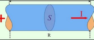
Let us recall the definition (Fig. 1): electricity is the amount of charge driven by the forces of an electric field that overcomes the conventional plane of a conductor, called the cross-section of the conductor, per unit time.
Rice. 1. Definition of current strength
Thus, if the electric charge passed through a conductor in a certain time is known, then it is not difficult to find the value of this charge passed per unit time, that is: I = q/t
Through power and voltage
The passport of an electrical appliance usually indicates its rated power and the parameters of the electrical network for which it is intended to work. Having this data at your disposal, you can calculate the current using the formula: I = P/U .
This expression follows from the formula for calculating power: P = IU .
Through voltage or power and resistance
The strength of electricity in a section of a circuit is determined by Ohm's law. To do this, you need to know the following parameters: resistance and voltage in this area. Then I = U/R . If the load power is known, then it can be expressed through the square of the current multiplied by the resistance of the section: P = I2R , from where
For a complete circuit, this value is calculated according to Ohm’s law, but taking into account the parameters of the power source.
Through EMF, internal resistance and load R
Using Ohm's law adapted for the complete circuit, you can calculate the maximum current using the formula I = ε / (R+r′) if the parameters are known:
- external resistance of conductors (R);
- EMF of the power source (ε);
- internal resistance of a source with EMF (r′).
Note! Real power supplies have internal resistance. Since in an electrical circuit, the current indicator may decrease due to an increase in the resistance of the power source or as a result of a drop in EMF. It is because of the increase in internal resistance that the battery runs out and the EMF of the batteries weakens.
Joule-Lenz law
It would seem that calculating the current strength based on the amount of heat released as a result of heating the conductor has no practical application. However, it is not. Let's look at this with an example.
Suppose you need to find the current strength during operation of the electric kettle. To do this, bring 1 kg of water to a boil and record the time in seconds. Let's assume the initial temperature was 10 ºC. Then Q = Cm(τ – τ0) = 4200 J/kg × 1 kg (100 – 10) = 378,000 J.
Rice. 2. Joule-Lenz law
From the Joule-Lenz law (image in Fig. 2) the formula follows:
By measuring the resistance of an electrical appliance and substituting the values into the formula, we obtain the amount of current consumed.

