History of invention
The Italian scientist Alessandro Volta, after conducting a series of experiments with electricity, comes to the conclusion that electric current can be obtained by combining metals with liquid.
By placing copper plates coated with zinc in acid, in 1800 he created the first electrochemical energy source, later called the “voltaic column”. He also establishes that when two different metals are joined, a force is generated, which is expended in the work of moving an electric charge from one point to another. In this case, the displaced charge changes its potential (the amount of energy) it possesses. The difference between the initial potential and the final potential is called “voltage”.
To measure the amount of electricity, Volt uses a metal rod inserted into a rubber stopper and placed in a bottle. He puts straws on the lower end, located in the bottle, and a ball on the other. The scientist observes that when the ball comes into contact with an electrified substance, the straws repel. This allows him to judge the degree of charge of the material.
Volt proved the existence of voltage by conducting the following experiment. A copper and zinc disk was placed on the electroscope (a device that records charge). A thin layer of dielectric is laid between them. For a short time, the physicist connected the metals together with a wire. The petals on the electroscope moved slightly apart. Next, the disks moved apart to a greater distance, while the recorder petals diverged even more.
In fact, this was the first experiment to measure, albeit in rough form, voltage. In 1830, the English scientist Michael Faraday discovered the phenomenon of electromagnetic induction, which was subsequently used to create a number of electrical measuring instruments.
In 1881, French physicist Arsene D'Arsonval created a device consisting of a coil and a pointer placed in a constant magnetic field. Electric current was supplied to the coil, causing the needle to deviate from its initial position. In the same year, the International Electrotechnical Congress was held, at which the designations of electrical quantities were adopted. The device designed to measure potential differences was called a voltmeter, and voltage began to be measured in volts.
Resistance and measurements
We've sorted out the voltmeter, but what should be the resistance of the ammeter so that it does not affect the operation of the circuit and shows the current strength accurately? Since the ammeter is connected in series to the circuit, its internal resistance will limit the current in the circuit.
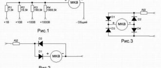
For example, let’s calculate how much current flows in circuit 1 if the power source voltage E is 10V, and a 5-ohm resistor R1 is used as a load.
So, the current in the circuit should be 2 amperes, and now we connect a conditional ammeter to the circuit, the resistance of which is 1 Ohm, then it will show the current:
The difference between the current measured by the ammeter and the calculated one by almost a quarter is due to the high resistance of the ammeter. That is, the lower the resistance of the ammeter, the less it affects the current in the circuit. Accordingly, the ammeter resistance should be much less than the load resistance (Ra
Voltmeter. A device for measuring voltage in an electrical circuit
We all know that the voltage in a household outlet is 220 V (it is worth remembering that this is not the case in all countries). But sometimes it can be more or less, and a logical question arises - how to measure the voltage? For this we need a voltmeter. And so, a voltmeter is a device that measures potential difference (in Volts) or voltage. The principle of operation of a classic voltmeter is quite simple - the current that is induced in the coil when connected to a voltage source creates a torque that moves the needle of the electrical measuring instrument. The deflection of the needle is always directly proportional to the potential difference between the measured points. It is worth remembering that the voltmeter is ALWAYS connected in parallel to the circuit in which the voltage is measured.
How to connect a voltmeter in a car?
As mentioned above, the easiest voltmeter to connect is one designed for installation in the cigarette lighter socket. You just need to plug in such a device instead of the cigarette lighter itself, and that’s it. You can also use an extension cord or tee for the same connector to install it. This will be convenient if you use the cigarette lighter socket for something else - to power the DVR, charge your smartphone, or for its intended purpose.
With wired models you will have to tinker. First consider a voltmeter that has only two wires. Typically, they always come in two different colors, such as red and black. If the voltmeter you bought is not an outright fake, then the red wire is “plus”, and the black wire, respectively, is “minus” or “ground”.
Any voltmeter in the car is connected directly to the battery. It is better if through a fuse. This is how, by the way, almost all cigarette lighter sockets are connected - directly to the battery through a fuse. It is best to extend the corresponding wires for connecting the voltmeter to the battery yourself. As an alternative, you can try to find the “plus” and “minus” under the instrument panel trim, or in the place where the car radio is connected. However, we repeat, it is best to run separate two wires directly to the battery, installing a fuse in the gap in the positive wire.
Types and types of voltmeters
All voltmeters can be divided according to: principle of operation, purpose, method of application and design.
Based on the principle of operation, devices are divided into groups:
- Electromechanical voltmeters.
- Electronic voltmeters.
Let's look at each group specifically.
These measuring instruments are direct conversion devices. The measured value in them is converted directly into readings on the scale of the reading device. It is intended for visual assessment of the measured voltage.
The scale looks like a sequence of marks with numbers and forms a fixed part of the device. The distance between two adjacent marks is the scale division value. Scales can be linear and nonlinear, one-sided (o is located at the beginning) and two-sided (o is located in the middle). A number is usually written on the scale indicating the accuracy class of the device.
The moving part of the device consists of a frame located between the poles of a permanent magnet. Current flows through the frame winding. An arrow is associated with the movable frame, by the magnitude of the deflection angle of which you can use a scale to estimate the value of the measured parameter. This angle directly depends on the current flowing through the frame winding, and therefore on the voltage value that is measured.
Such devices use the magnetoelectric method for measurement. It is most often used in electromechanical instruments to measure various physical quantities.
It should be noted that such devices are rarely used separately. As a rule, they are an integral part of devices with more complex circuit design.
In addition to the magnetoelectric measurement method, others are used in electromechanical devices: electromagnetic, electrodynamic, ferrodynamic, thermoelectric, and rectification method.
Based on the requirements for voltage meters, the use of these devices is more preferable than electromechanical ones. And these requirements are as follows: reducing the methodological measurement error.
To measure voltages at various points in the circuit, a voltmeter is connected in parallel to the circuit being measured. Therefore, its use should not distort the real picture. It should not bypass a section of the circuit; therefore, its input resistance should be large (ideally, it should tend to infinity).
Electronic voltmeters can be divided into two groups. One is made up of analog devices, the other is digital. The difference between them lies in the form of providing information about the measurement results.
The input voltage, the value of which needs to be measured, is supplied to the scaling device. It is made in the form of a high-precision multi-limit resistor divider. The number of resistors corresponds to the number of voltage measurement ranges.
We recommend reading: MOSFET transistors - what they are, operating principle
After the resistor divider, the signal goes to a direct current amplifier (DCA). Its purpose is to amplify the input voltage passed through the divider to the value required for normal operation of the indicating device. The UPT is also necessary to increase the input resistance of the device and match it with the low-resistance winding of the indicator frame of the magnetoelectric system.
The design of the electromechanical device, by which the measured voltage value is measured in analog voltmeters, was discussed above.
The high input impedance of this device is determined mainly by the UPT circuit. It widely uses transistors connected according to an emitter signal follower circuit, or field-effect transistors.
The accuracy of analog voltmeters is determined by the accuracy class of the input device resistors and the accuracy class of the microammeter head, along the arrow of which the measured voltage is read.
To measure small voltages, the use of a direct current amplifier in the device circuit does not always lead to sufficient measurement accuracy.
In millivoltmeters, measurements are made on alternating current. The DC input voltage is converted to AC using its own modulator. The AC amplifier has better characteristics in terms of linearity, zero drift, and gain, which is slightly dependent on temperature. After amplification, the alternating voltage is detected. A stable rectified DC voltage is supplied to the pointer electromechanical device.
If you need to measure alternating voltage with a voltmeter, its circuit will change. There are two types of schemes.
In one, the input voltage is detected and then amplified by a DC amplifier.
In circuits with a different design, the input AC voltage is first amplified by an AC amplifier. After this, the signal is rectified by the detector.
Depending on the requirements for the measurement results, either one circuit design or another is selected.
The first option is used where it is necessary to make measurements in a wide frequency range (from 10Hz to 1000MHz).
The second construction option is used when measuring very small alternating voltages (units of microvolts).
Meters of this type during processing represent the input voltage in the form of steps (discrete values). Its value is displayed digitally on the device indicator.
The input device (ID) determines the scale of the input signal and filters it from interference. When measuring alternating voltage, it is rectified. Thus, the VU circuit contains a voltage divider, a network noise filter, and a signal amplifier.
A filter is necessary to increase the accuracy of measurements, because the interference signal can be perceived as a useful signal and after its sampling, numbers that do not correspond to the measured value of the useful input signal will be displayed on the output indicator.
“Advanced” models additionally have devices that select polarity and measurement limits automatically.
An analog-to-digital converter (ADC) represents the voltage at the input of the device in the form of a time interval, the duration of which depends on its value. This interval is filled with pulses generated by the voltmeter’s own generator. The counter, based on the commands of the control device, counts them and a digital value proportional to the number of pulses appears on the digital indicator of the device.
Since the electronic components of the VU have significant input resistance, digital voltmeters have very little effect on the resistance of the section of the circuit on which the measurement is made. The accuracy of their readings is much higher than that of all previous voltmeters.
Working with the device has become much easier. There is no need to make an additional recalculation of the obtained value taking into account the selected scale and the set multiplier (as with analog voltmeters). But the requirements for the quality of the supply voltage are very high.
Operating principle
All devices used to make measurements in electrical networks are divided into two groups: electromechanical and electronic.
Electromechanical devices
These are pointer instruments. The arrow in them is fixed on a frame on which a wire is wound. This coil is located on the same axis with a permanent magnet in devices used in direct current networks, or with another coil in alternating voltage devices.
Reference. An AC device will not work in a DC network, but a device for measuring DC voltage, if connected through a diode bridge, can be connected to an AC network with loss of accuracy.
When current passes through the winding, an electromagnetic field is induced in it, interacting with a magnet or other winding, and the frame rotates. The rotation of the coil with the arrow is prevented by a spring, so the angle of rotation of the frame corresponds to the current through it and the potential at the terminals.
To reduce pointer vibrations, an electromagnetic damper made of an aluminum plate or a pneumatic damper made of a piston and cylinder is installed.
To increase accuracy, the arrow is equipped with counterweights that eliminate the influence of gravity, and the mechanism itself is made of alloy steel to reduce wear.
Electronic devices
In electronic devices, the sensitive element is an electronic board that converts the input signal into instrument readings. Such a device can receive power from the measured voltage or another source - internal batteries or external power.
There are two types of electronic voltmeters:
- Analog. They contain a converter of the input signal into the angle of rotation of the arrow, showing on the scale the value of the measured voltage. The disadvantage of analog circuits is the need to recalculate the scale readings when the measurement limit changes;
- Digital. Such devices have a digital display and a converter that displays the input signal in digital form. When connecting the device to a DC network, the polarity of the connection is shown on the display. These designs are compact, and the accuracy of such a device depends on the quality of the built-in controller.
Principle of operation
Electromechanical type meters were the first to be created. They operate using the magnetoelectric principle. A permanent magnet is fixedly fixed, and a steel core is installed between its poles. This structural element is installed in such a way that a constant electromagnetic field can be formed in the annular air gap.
A frame made of aluminum is installed in the gap on the axle shafts. She is able to move freely. There is also a spool of thin wire on the frame. The indicator arrow of the device is attached to the frame using springs. As soon as an electric current begins to pass through the device, an electromagnetic field appears in the winding. The frame interacts with it and deflects along with the arrow to a distance corresponding to the voltage value.
The design of the meter also contains an induction damper - an aluminum plate mounted on a frame with an arrow. In accordance with Lenz's rule, eddy currents arising in the damper interact with the magnetic field that generated them and slow down the oscillations of the device pointer. To achieve the required measurement accuracy, the device must not be exposed to gravity during operation.
To solve this problem, the moving part of the meter is equipped with a system of weights moving on rods. In addition, to ensure accurate measurements, it is necessary to reduce the friction force of the steel tips. This is achieved through the use of special wear-resistant steels. Parts made from them are polished.
Before starting the measurement, the user needs to set the indicator arrow to the zero position.
For this purpose, the design of the device includes a special adjustment screw connected to a spring. This is a classic design, but today there are devices containing magnets of different shapes. Moreover, in some designs the magnet is movable.
We recommend reading: How to make an adjustable power supply from a charger
Changing measurement limits or why additional resistance and shunt are needed
In a voltmeter the resistor is called an additional resistor (Rd), and in an ammeter it is called a shunt resistor or simply a shunt (Rsh). The difference in the names of these elements is due to their connection. Each measuring mechanism has some kind of measurement limit, usually hundreds of micro- or tens of milliamps and a certain internal resistance.
In a voltmeter, an additional resistor limits the current through the measuring mechanism and increases the input resistance of the device. By changing its resistance, it is possible to measure different voltages using the same mechanism.
For example, there is a measuring mechanism with the following characteristics:
— total deviation current 500 μA;
Accordingly, it can measure current up to 500 micro
ampere (0.0005 ampere) or voltage up to:
U = IR = 0.0005×650 = 0.325 volts
To measure a higher voltage, you need to connect an additional resistance in series with the measuring mechanism, then part of the voltage will drop across this resistance, and the same 0.325 volts will remain on the measuring mechanism.
Let's try to calculate the resistance of the additional resistor. Let's say we want to measure voltage up to 5 volts, the total resistance of the voltmeter is equal to the sum of the resistances of the additional resistor Rd and the measuring mechanism Rim:
We know the total deflection current of the needle - 0.0005 A, the future measurement limit is 5 volts, then the total resistance of the device should be:
R = U/Imeas = 5/0.0005=10,000 Ohm
To find the resistance of the additional resistor, you need to subtract the resistance of the measuring mechanism from the total resistance:
Rd = Rtot-Rim = 10,000 – 650 = 9,350 Ohm
Conclusion - to make a voltmeter with a measurement limit of 5 V, you need to connect an additional resistor with a resistance of 9350 Ohms to the measuring mechanism.
You can find the resistance of the additional resistor a little differently:
Where U is the future measurement limit, Umeas is the current measurement limit
The result, as you can see, was the same.
Now let's look at the ammeter
. The main task of the shunt is to pass a current exceeding the limit of the measuring mechanism. We find the total resistance of the ammeter using the resistance formula for resistors connected in parallel.
Let's say we need to measure current up to 50A. We can repeat calculations similar to the above, but we can do it simpler: first we find the relationship between the shunt current and the current of the measuring mechanism, and then the resistance of the shunt.
That is, a current of up to 0.0005A can flow through the measuring mechanism, which means that the current will flow through the shunt:
Ish = Itotal-Imeas = 50–0.0005 = 49.9995 A
Then we find the ratio of the shunt current to the current of the measuring mechanism (Q):
Q = Ish/Imeas = 49.9995/0.0005 = 99,999
Now let's find the shunt resistance using the formula:
Rsh = Rmeas/(Q-1) = 650/99,998 = 0.0065 Ohm
The shunt resistance will be only 0.0065 Ohm.
Note: calculations of the shunt and additional resistance were carried out according to the book Metrology, standardization and technical measuring instruments by the authors Tartakovsky D.F., Yastrebov A.S., M.: Higher School 2001.
By changing the resistance of the shunt or additional resistor, you can change the measurement limits of voltmeters or ammeters. In this case, an ammeter can be made from a pointer voltmeter and vice versa. To do this, remove the “extra” components, leave the measuring head and select a resistor or shunt for it.
In practice, you can find shunts on sale with the required resistance and measurement accuracy; independent production of an accurate shunt is complicated by the difficulty of measuring such low resistances.
You also need to take into account that any additional element affects the circuit, as it has its own resistance. Consequently, when current flows through it, it will heat up, that is, power losses will occur. Current transformers are often used to measure current more efficiently and safely.
To measure high voltage, for reasons of electrical safety and galvanic isolation, voltage measuring transformers are used. And when measuring very low voltages, the voltmeters described in the article will inevitably introduce their own errors and affect the operation of the circuit. Therefore, electronic measuring instruments with high input impedance are used. An electronic voltmeter will not necessarily have a digital screen; it may also have a pointer type, but an electronic circuit will be installed at the input, for example, a transistor amplifier or other solutions.
In voltmeters and ammeters, in addition to a shunt or an additional resistor and a measuring mechanism, there may also be a rectifier. This solution is used in cases where a magnetoelectric measuring mechanism is used. It can only measure direct current, so to measure the alternating current is converted to direct current (rectified).
Connecting a voltmeter
The voltage at the power source or circuit element is measured by a device that is connected in parallel with the device.
The coil of the device has low resistance, and when connected directly to the network, the current will be large. To reduce current consumption and the effect on the electrical network, additional resistances are connected in series with the device.
Important! When the voltmeter is connected in series with the load, it will show the voltage of the power source with an error due to the load resistance. An ammeter is connected in series.
Constant pressure
Methods for measuring DC voltage depend on its magnitude:
The measurement limit is increased by connecting in series with the additional resistance device Rext. To increase the limit by n times, the total resistance must also be increased by n times and, taking into account the resistance of the device Rpr, Rext=Rpr*(n-1). The scale readings are also multiplied by n.
AC voltage
Methods and types of devices for measuring in alternating current networks depend on the voltage and frequency of the network:
Important! An AC voltmeter shows the actual voltage value. With a sinusoidal shape, its value is √3 (1.7) less than the amplitude.
Extension of the measurement limits is carried out by switching on through an isolating or autotransformer, as well as by using additional resistance. Its value is calculated similarly to measurements in a DC network.
When using an isolation transformer, the device readings are multiplied by the transformation ratio n=U1/U2.
The voltmeter must be connected according to certain diagrams. This is done to ensure that the device readings correspond to the network parameters.
How to use a multimeter
When working with the tester, you must follow the recommendations specified in the operating instructions.
Constant pressure
The chain is pre-broken.
- The red probe is connected to the “V Ω ma” connector.
- Black – connects to the “COM” socket.
- The rotary switch selects the estimated DC voltage limit “DCV”.
- If the value is unknown, the maximum is set, then successively decreased by one position.
- The free ends of the probes are connected to the circuit.
- The voltage shown on the display is recorded.
If there is a “HOLD” button, it can be used to “freeze” the current value on the display.
AC voltage
The operating algorithm is similar. Only the rotary switch is moved to the ACV position.
Why is the voltmeter always connected in parallel?
The resistance of an ideal voltmeter is infinity. But this is for the ideal; for the real it is much less, but still very high. Therefore, when a measuring device is connected to a circuit in series, its readings will have nothing to do with the truth, and its internal resistance will have a significant impact on the electrical circuit (practically an open circuit due to the high internal resistance).
The voltmeter is always connected in parallel to the circuit, so that the voltage drop across the meter has no effect on the operation of the electrical circuit. Also, if the measuring device is multi-limit (for example, 3, 15, 75 and 150 V), when switching the limit in series with the measuring coil, an additional resistance is introduced (as a rule, it is already installed in the device body, but it is worth clarifying this in the data sheet), which protects the measuring coil of the electrical device from currents higher than rated and ensure measurement accuracy.
Additional resistor
Modern measuring instruments are supplied with an additional resistor connected in series with the winding of the tester or voltmeter. It reduces the load on the coil, part of the voltage falls on the resistance. This value is known in advance and is also proportional to the resistance of the resistor. If there is no such resistor on old laboratory voltmeters, it is connected separately, and then calculations are carried out. Digital measuring devices do this automatically - turning the knob sets the appropriate multiplier.
The maximum measured voltage value depends on the resistance of the additional resistor. For most household testers, the peak voltage is:
- constant – 1000 V or 1 kV;
- alternating – 200 V.
To manufacture the resistor, a material with low temperature resistance is used, which eliminates the dependence of the device readings on thermal parameters.
Share on social networks: October 21, 2022, 14:10 Physics 0.00% 00
Connection diagrams and methods
The question often arises of how to connect an ammeter, in series or in parallel. Connecting the device in question into an electrical circuit break is not difficult. For safety reasons, this procedure is performed when the power source is turned off. You need to make sure in advance that the maximum current will not exceed the permissible values of the device. Such scales are duplicated in the accompanying technical documentation. When the supply voltage is applied, readings are taken. You need to wait until the needle stops oscillating. When it moves in the opposite direction, the polarity of the connection changes. If the current is too high, additional shunting is used.
The connection diagram of the device can be direct or indirect. In the first case, the device is directly connected to the electrical circuit between the power source and the load.
Before connecting the device, you must consider:
- direct or alternating current in the electrical network;
- Is the polarity of the device correct?
- the arrow of the device should be located beyond the middle of the scale;
- limits for measuring the maximum possible current surges in the circuit;
- whether the external environment meets the recommended indicators;
- Is the measurement location free from vibration?
Connecting the device
In DC circuit
Direct current can pass through different electrical circuits. As an example, we can cite all kinds of chargers and power supplies. To repair such devices, the technician must have an understanding of how the ammeter is connected to the electrical circuit.
At home, such skills will also not be superfluous. They help a person who is not too keen on radio electronics to determine for himself, for example, the time it takes to charge the battery from a camera.
To conduct the experiment, you will need a fully charged battery with a nominal voltage of, for example, 3.5 V. In addition, you need to use a lamp of the same rating to create a series circuit:
- battery;
- ammeter;
- bulb.
The entry that is marked on the measuring device is recorded. For example, a lighting fixture will consume 150 milliamps of electricity, and the battery has a capacity of 1500 milliamp-hours. Therefore, it will work for 10 hours, delivering a current of 150 mA.
Connecting to the charger
The question often arises of how to properly connect an ammeter to a charger. When using a charger, the need arises to measure the current. This will make it possible to control the process of accumulating electricity by the battery, and avoid overcharging and undercharging. As a result, the service life of the battery will increase significantly.
When operating a large number of technical devices, it becomes necessary to control the current strength. The ammeter needles or indicators on the monitor of a discrete device will show the operator such a physical parameter. The measurements taken are needed to maintain the operating condition and to signal the occurrence of an emergency.
We recommend reading: The simplest low-frequency amplifiers using transistors
How to use a voltmeter in a car?
Now the most interesting thing is how to find out all the information that was listed at the beginning of the article using simple numbers on a voltmeter? Let's go in order.
What % is the battery charged?
The percentage of battery charge can be determined by how many volts it produces at rest. The latter is a very important condition that must be fulfilled. That's why we'll start with it. How to bring the battery to rest? You just need to let it sit for 8-12 hours. The battery is usually in this state in the morning if the car was previously used yesterday and was not parked late in the evening. Overnight, the battery “calmed down”, the voltage on it leveled out, and from it you can determine how many percent it is charged.
How it's done? A fully functional car battery at rest should produce a voltage from 11.7 V to 12.7 V. Moreover, if the voltmeter shows 12.7 V, then the battery is 100% charged, and if 11.7 V, then it is on the contrary, it is discharged to zero. Let us remind you that the battery must be settled, and no load (music, dimensions, gadgets, etc.) must be turned on at the time of measurements.
The beauty of this method is that from the voltage of the battery, which is at rest and without load, intermediate values can be determined as a percentage. To do this, it is enough to compare tenths of a volt with tens of percent. For example, if the battery voltage is 12.6 V, then subtract 10% from 100%, and we get the battery charge to 90%. Accordingly, 12.5 V is 70%, and so on, until completely discharged.
Before you start using this technique, it would be a good idea to check the leakage current when the car is turned off and all devices are turned off. If any consumers are in sleep mode, they can draw quite a lot of current from the battery. This will cause a voltage drop, and the data obtained using the described method will be inaccurate. The most accurate % can only be found when the battery is completely disconnected from the on-board network. If the leakage current is normal (50-100 mA), then the charge percentage will be very accurate.
How does the battery hold the load while starting the engine?
During operation of the starter, the battery experiences the greatest load, incomparable to other consumers of the car. The currents at this moment reach hundreds of amperes, which causes a very noticeable voltage drop even on a new and fully charged battery.
So here it is. If you pay attention to the voltmeter while starting the engine, you can find out how well your battery can handle a heavy load. If the battery is fully operational and not very worn out, then the drawdown should be no more than 2-3 tenths of a volt. That is, if you got into the car in the morning and the voltage was 12.5 V, and during the process of starting the engine it dropped to 12.3 V, then this indicates that the battery is holding the load perfectly.
This method, by the way, allows you to determine not only the health of the battery, but also the starter itself. If, for example, you have a completely new (or relatively fresh) battery installed, which you are confident in, and the voltage drop at start is still huge (drops to 11-10 V or lower), then this means that there are obvious problems with the starter . It either jams, or there is wear on the brushes, or a short circuit in the windings. Poor contact at the starter terminals can also cause specific voltage drops.
Is the battery charged normally from the generator?
When the engine is up and running, the alternator must produce electricity, some of which is returned to the battery, charging it. To determine that charging actually occurs and allows you to determine the device in question here.
How much should the voltmeter show when the car is running? Here the indicators vary quite a lot on different cars. If we take the ideal voltage, which indicates a fully charged battery, then it corresponds to 14.4 V. But there are several nuances.
- Firstly, if the battery was heavily discharged before starting the engine, then in the first minutes the charge voltage will be slightly lower than it should be. It may even be less than 14 V (13.7-13.8, for example). This is fine. Over time, it will increase and reach the specified parameter.
- Secondly, normally the charge voltage differs on different cars. It depends on the generator, and on the speed of rotation of the crankshaft, and on the characteristics or serviceability of the relay regulator. In general, if the charge voltage is very different from the ideal 14.4 V, then you should take your car to a good auto electrician.
- Thirdly, at negative ambient temperatures, it is believed that the battery is generally not able to accept a charge from the generator for the first half hour. It follows that immediately after starting in severe frost, the charge voltage will be far from ideal. If the entire system is working properly, then after warming up the engine compartment and the battery itself, the voltmeter readings will level out.
Connection process
What does a voltmeter measure?
To take readings of the network voltage in a certain section of the circuit, a voltmeter is connected to it only in parallel, regardless of the type of device, since in this case it has minimal influence on the movement of electric current. Voltage monitoring with this meter can be carried out both at the load and at the power source.
Diagram of parallel connection of a voltmeter to a network
When a voltmeter is wedged into an electrical circuit in series, it actually breaks due to the high internal resistance; accordingly, the measurements obtained will be incorrect, and in many cases a short circuit or failure of the circuit elements, including the meter, may occur.
On a note. Do not confuse a voltmeter with an ammeter, which is connected to the mains in series, since the resistance when measuring current should be minimal.
The device is connected to two sections of the circuit by clamping the wires with special electrodes or clamps.
If you need to measure sections of a DC electrical circuit with a known high voltage or you need to obtain ultra-precise data on this parameter, then you should use additional resistance, which is created by resistors - the simplest voltage dividers.
Connecting additional resistance (resistors) to the circuit to increase the accuracy of the voltmeter
When making measurements in high-voltage AC power networks, you can use not only resistors, but also instrument transformers as additional resistance. It is with alternating current that electricians usually use voltage transformers, since they not only reduce the voltage for the end user, but also separate the measuring circuit from the power circuit.
Appearance of the voltage transformer
Rules for connecting voltmeters to a circuit:
- The correct measuring range of the device must be selected. You cannot measure high voltage with a voltmeter, which is designed for measuring the parameters of microcircuits;
- If the device reading is close to the limit value, you should work with it carefully, since a jump in the EMF can damage its windings;
- The pointer device must be positioned according to the instructions: either vertically or horizontally. When monitoring readings, it is recommended to exclude the influence of electromagnetic fields on the device and vibration waves;
- Voltmeters can be connected to a circuit that is already energized, however, at dangerous values of this indicator, it would be useful to use special gloves and a dielectric cloth (mat);
- If the arrow in an analog device gives a non-zero result before starting to take readings, then it is necessary to reset it with a regulating element - a screw;
- Periodically, it is necessary to carry out calibration measures on the device, which will guarantee the accuracy of the measurements it produces;
- When using the device for the first time, it is worth connecting it to a de-energized network - only when all the terminals and wires of the device are connected, the current turns on;
- During measuring procedures, to avoid injury, it is recommended that you familiarize yourself with the safety precautions specified in the instructions.
When monitoring voltage in different circuits, various voltmeters and additional devices (resistors, transformers for them) can be used; to obtain ultra-precise measurement results, it is important to take into account the features of each of them.
Application of a multimeter
In most cases, it is convenient to use specialized instruments to carry out measurements. There are a large number of varieties, the use of which allows serial and parallel connection in a circuit. The connection diagram of the voltmeter implies only a parallel connection.
In some cases, you can use a multimeter. This measuring device operates on a universal principle. It can be used to measure various electrical quantities, including DC and AC voltage. To do this, you need to take the following steps:
- Set the switch to the appropriate mode for measuring DC or AC voltage.
- Select measurement range. To do this, you need to point to the nearest value that exceeds the expected one.
- Connect the black and red probes. The first is inserted into the COM socket, the second into the adjacent one marked V.
- The probes are connected in parallel to the part being measured, maintaining the correct polarity.
- The display shows the measurement result.
After finishing work, the mode switching knob should be moved to the “Off” position. The advantage of using a multimeter is its versatility and ease of use.
Security measures
Unlike other devices, such as an ohmmeter or a megometer, when working with a voltmeter, you have to deal with voltage. At small values it does not pose a danger to humans. Great care must be taken when measuring voltages that can create a dangerous current flowing through the human body.
Voltage measurements must be accompanied by full compliance with safety regulations and operating regulations. This will prevent electrical injury. It is prohibited to work without protective equipment, such as rubber gloves and mats. Upon completion of the work, there should be no exposed live parts that could cause accidental contact by maintenance personnel.
The widespread use of voltage measurement in electrical engineering has led to the creation of voltmeters of various designs. They differ both in operating principle and in accuracy. The most popular are universal devices that can automatically select not only the limit, but also the type of controlled value.
Measuring current with an ammeter
An ammeter measures the current in a circuit, through a load or through an individual element. Therefore, to measure current, an ammeter is connected in series
, otherwise similar to the voltmeter:
— When measuring direct current, you need to take into account the polarity, that is, the plus of the ammeter to the plus of the power source, and the minus to the load. You can connect the other way around - the plus of the ammeter to the load, and the minus to the minus of the power source.
— When measuring AC current, polarity does not need to be taken into account.
— When choosing a device, it is also important to pay attention to the type of quantity being measured.
Why should the ammeter resistance be significantly less than the circuit resistance?
In order for the ammeter not to noticeably change the total resistance of the circuit, its own resistance, as follows from formula (54.2), must be small compared to the resistance of the circuit. Therefore, ammeters are made with very low resistance (a few tenths or hundredths of an Ohm).
Interesting materials:
How many characters are on one Word page? How many story missions are there in Metal Gear Solid 5? How many fairy-tale heroes have pulled turnips? How many declensions do creatures have? How many syllables are pencils? How long do service dogs last? How long does it take to become a police captain? How long does mascara last? How long to serve in the army with a bachelor's degree? How much tar and nicotine is in Winston blue cigarettes?
general information
Voltage ( U ) is an important parameter of the electrical network, which shows the ratio of the work done by the electric field to move the charge (A) to the value of the charge itself ( q ):
U=A/q.
Volts are a unit of measurement for electrical voltage.
Schematic definition of electrical voltage
A voltmeter is a measuring device that reads electrical voltage in various circuits and has a high resistance. Voltmeters come in different types:
- By purpose:
- for alternating or direct electric current;
- phase;
- impulse sensitivity;
- universal (multifunctional);
- selective frequency search.
- By installation method:
- stationary;
- autonomous;
- panel
- According to the measuring principle:
- switches;
- digital;
- static.
Each of them has its own characteristics in structure, measurement principle and purpose, as well as its own unique appearance.
Important! On electrical diagrams, this measuring device is designated by the letters “V” or “PV”.
Direct configuration multi-range voltmeter
In this voltmeter configuration, each multiplier resistor RS of the multi-range voltmeter is connected in series with the meter as before to obtain the desired voltage range. So, if we assume that our 50mV FSD meter is required to measure the following voltage ranges: 10V, 50V, 100V, 250V and 500V, then the required series resistors are calculated in the same way as before:
Reducing the circuit of a direct multi-range voltmeter from:
While this direct voltmeter configuration works very well for reading our voltage range, the multiplier resistor values needed to get the meter's correct FSD for the calculated ranges may produce resistor values that are not the standard preferred values, or require resistor soldering to obtain an accurate value.
The values we calculated from 99.5kΩ to 4.9995MΩ are not commonly accepted resistor values, so we need to find a variation on the voltmeter design above that will use more commonly available resistor values.