Inverters are used in cases where it is impossible to obtain alternating current (AC) voltage from the network. Inverters are designed to convert direct current (DC) voltage into alternating current (AC) voltage and are divided into two types: pure sine wave inverters and modified square wave inverters. Pure sine wave inverters are quite expensive, but modified square wave inverters are significantly cheaper.
In this article we will look at creating a pure sine wave inverter using an Arduino board.
If you decide to repeat the creation of the circuit discussed in this article, please note that it has neither overcurrent protection, nor short circuit protection, nor overheating protection. This design diagram is provided for educational purposes and is not recommended for industrial use. However, you can add the named protection schemes to this project if you wish - there is a lot of detailed information about them on the Internet.
Warning : Be extremely careful when working with the circuit presented in this project, as it uses high voltages and voltage pulses generated by switching the signal at the input of the circuit.
What is sinusoidal PWM (SPWM)
SPWM stands for Sinusoidal Pulse Width Modulation and is translated as sinusoidal PWM (pulse width modulation). We previously looked at it in the sine and square pulse generator on Arduino.
As we know, in PWM we can change its duty cycle (busy factor, duty cycle), that is, the ratio of periods of activity (on-time) and inactivity (off-time). Thus, by changing the PWM duty cycle, we change the average pulse voltage. This is clearly shown in the following picture.
As can be seen from the picture presented, with a duty cycle (fill factor) of 100% we get an average output voltage of 5V, with a duty cycle of 50% we get an average output voltage of 2.5V, and with a duty cycle of 25% we get another 2 times less.
Sine wave voltage is an analog voltage that changes its amplitude over time, so we can reproduce the "behavior" of a sine wave by continuously changing the duty cycle of the PWM wave (signal), as shown in the following figure.
If you look at the diagrams presented below in this article, you will see that a capacitor is connected to the output of the transformer - it is precisely responsible for smoothing such an alternating current signal.
The input signal used will charge and discharge the capacitor according to the input signal and load. We will use a SPWM signal (sine wave PWM signal) of high frequency, it will have a very small duty cycle of 1% at first, this 1% will charge the capacitor just a little, a signal with a duty cycle of 5% will charge the capacitor a little more, a duty cycle of 10% will charge the capacitor is even larger and gradually we will reach a duty cycle of 100%, and after that we will reduce the duty cycle to 1%. This process will produce a very smooth curve, much like a sine wave. Thus, by providing the correct duty cycle at the input, we will get a good sine wave at the output.
Where can I buy
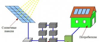
An inverter is a device that is not a consumer product, so it cannot be purchased in a regular store or supermarket. The sale of such products is carried out by specialized organizations and retail chains focused on alternative types of energy used for autonomous power supply of various types of objects.
If the consumer already has a solar power plant or wind generator installed, then it is best to purchase a model from the manufacturer whose equipment is already in use. To do this, you need to find a dealer of this company and enter into a supply agreement with him.
If a new autonomous power supply system is created and the user independently completes it, then you can go in several ways, these are:
- Again, find a dealer of a company that produces such devices and purchase the product from him.
- Contact a trading company that sells devices from this group of products.
- Search for the required device on the Internet, where a fairly wide range of similar devices is presented.
How does an inverter based on an SPWM signal work?
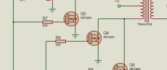
The circuit of such an inverter is shown in the following figure.
As you can see, we used two N-type MOSFET transistors and a half bridge to drive the transformer in the circuit. To reduce unwanted noise and protect the MOSFETs, we used two 1N5819 diodes in parallel with the MOSFETs. To reduce possible unwanted pulses generated in the control section, we used 4.7 Ohm resistors connected in parallel with the 1N4148 diodes. And finally, transistors BD139 and BD 140 are connected in a push-pull circuit to drive the gates of MOSFET transistors because MOSFET transistors have a very high gate capacitance and require at least a voltage of 10V at their gate to operate correctly.
For a better understanding of the operating principles of the presented circuit, we have shown half of it in the following figure. Consider the case when the MOSFET transistor in it is open - in this situation, the current flows first through the transformer and then through the MOSFET transistor is shorted to ground, thus, a magnetic flux occurs in the same direction in which the current flows, so the transformer core transmits this magnetic flux to the second winding and thus at the output we get the positive half cycle of the sinusoidal signal.
In the next cycle, the current flows in the opposite direction and, therefore, the magnetic flux appears in the same direction, therefore the direction of the magnetic flux in the transformer core also changes (compared to the previous case considered).
That is, now we know that the direction of the magnetic flux in the transformer changes. Thus, by turning on and off both MOSFET transistors (they are inverted with respect to each other) and performing these switchings 50 times per second, we will form a changing magnetic field in the transformer core, therefore, the direction of the current in the secondary winding of the transformer will change in accordance with Farad's law. This is the basic principle of operation of the inverter.
Now in the following figure we will look at the complete circuit of a pure sine wave inverter based on Arduino board.
As you can see from the presented diagram, switching the operating cycles of the above presented inverter circuit will be carried out using two digital pins of the Arduino board.
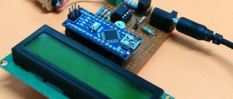
Project design
For demonstration purposes, we have assembled a circuit of our inverter on a stripboard (Veroboard). A huge current will flow at the output of the circuit transformer, so in this place the connectors (connectors) must be used as thick as possible.
Converters and their types
There are three types of 12-220 V converters. The first is from 12 V to 220 V. Such inverters are popular among motorists: through them you can connect standard devices - TVs, vacuum cleaners, etc. Reverse conversion - from 220 V to 12 - is required infrequently, usually in rooms with severe operating conditions (high humidity) to ensure electrical safety. For example, in steam rooms, swimming pools or baths. In order not to take risks, the standard voltage of 220 V is reduced to 12, using appropriate equipment.
Voltage converters are available in sufficient quantities in stores.
The third option is, rather, a stabilizer based on two converters. First, the standard 220 V is converted to 12 V, then back to 220 V. This double conversion allows you to have an ideal sine wave at the output. Such devices are necessary for the normal operation of most electronically controlled household appliances. In any case, when installing a gas boiler, it is strongly recommended to power it through just such a converter - its electronics are very sensitive to the quality of power, and replacing the control board costs about half the boiler.
Required Components
The complete list of components required to assemble our inverter is presented in the following table.
| No. | Name | Component type | Quantity | Where can I buy |
| 1 | Atmega328P | microcontroller | 1 | |
| 2 | IRFZ44N | Mosfet transistor | 2 | buy on AliExpress |
| 3 | BD139 | transistor | 2 | buy on AliExpress |
| 4 | BD140 | transistor | 2 | buy on AliExpress |
| 5 | 22pF | capacitor | 2 | buy on AliExpress |
| 6 | 10K.1% | resistor | 1 | buy on AliExpress |
| 7 | 16MHz | crystal oscillator | 1 | buy on AliExpress |
| 8 | 0.1uF | capacitor | 3 | buy on AliExpress |
| 9 | 4.7R | resistor | 2 | buy on AliExpress |
| 10 | 1N4148 | diode | 2 | buy on AliExpress |
| 11 | LM7805 | voltage regulator | 1 | buy on AliExpress |
| 12 | 200uF,16V | capacitor | 1 | buy on AliExpress |
| 13 | 47uF, 16V | capacitor | 1 | buy on AliExpress |
| 14 | 2.2uF,400V | capacitor | 1 | buy on AliExpress |
The appearance of these components is shown in the following figure.
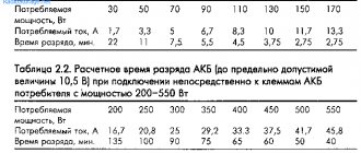
Testing the inverter operation
To test the operation of the inverter we used:
- Lead-acid battery with a voltage of 12V.
- Transformer with taps 6-0-6 and 12-0-12.
- A 40 W electric lamp as a load.
- Multimeter Meco 108B+TRMS.
- Multimeter Meco 450B+TRMS.
Output signal from Arduino board
After loading the code into the Arduino board, we measured the SPWM signal on two of its pins and got the following picture:
If we zoom in on this image, we can see each changing half-cycle of the PWM wave.
The following figure shows the signal at the output of the transformer.
Inverter in perfect condition
As you can see in the figure, in an ideal state the inverter circuit consumes approximately 13 W of electricity.
No-load output voltage
As you can see, with no load connected, the inverter output voltage is approximately 245 V.
Inverter input energy consumption
In the picture below you can see the input power consumption with a connected load of 40 W.
Inverter output energy consumption
In the presented figure you can see the output power consumption with a connected load of 40 W.
You can watch all these processes in more detail in the video at the end of the article.