The phrase about “ burning out zero”
“Every one of us has probably heard. Why does the mysterious zero tend to burn out all the time? In order to bring some clarity to this issue, it is necessary to recall something from a high school physics course.
For a single-phase circuit, "neutral" is simply the name for the conductor that is not at high potential with respect to ground. The second conductor in a single-phase circuit is called a “phase” and has a high alternating voltage potential relative to ground (in our country, most often only 220 V). The single-phase zero does not show any tendency to burn out.
The trouble is that all electrical communications (i.e. power lines) are three-phase. Let's consider a “star” circuit, in which the concept of “neutral wire” appears.
The alternating currents of each phase in three identical loads are phase shifted by exactly one third and ideally cancel each other out, so the load in such a circuit is usually called a three-phase concentrated load. With such a load, the vector sum of the currents at the midpoint is zero. Neutral wire
, connected to the middle point, is practically not needed, since no current flows through it. Minor current only appears when the loads on each phase are not completely equal and do not completely cancel each other out. Indeed, in practice, many types of three-phase four-core cables have a neutral core of half the cross-section. There is no point in wasting scarce copper on a conductor through which practically no current flows. The three-phase zero also does not show any tendency to burn out under a three-phase concentrated load.
Miracles begin when single-phase loads are connected to three-phase circuits. At first glance, this is the same case, but there is one small difference. Each single-phase load is a completely randomly selected device, i.e. single-phase loads are not the same. It is foolish to think that different single-phase consumers will always draw the same current. Single-phase loads
in three-phase circuits they always try to bring it as close as possible to
three-phase loads
. This means that when connecting single-phase consumers to a three-phase network, they try to distribute their power across different phases so that each phase carries approximately the same load. But complete equality is never achieved and it is clear why. Consumers randomly turn their electrical equipment on and off, thereby constantly changing the load on their phase.
As a result, complete compensation of phase currents almost never occurs at the midpoint, but the current in the neutral wire usually does not reach its maximum value equal to the highest current in one of the phases. That is, the situation is unpleasant, but predictable. All wiring is designed for it, and zero burnout
usually does not happen, and if it does, it is extremely rare.
This situation developed in the 90s of the 20th century. What has changed by this time? Switching power supplies have come into widespread use. This power source is used for almost all modern household equipment (TVs, computers, radios, etc.). The entire current of such a source flows during only one third of the half-cycle, i.e., the nature of current consumption is very different from the nature of current consumption by classical loads. As a result, additional pulse currents arise in the three-phase network, which are not compensated at the midpoint. Do not forget to add to this the uncompensated currents caused by the presence of single-phase loads in a three-phase network. In such a situation, a current often flows through the neutral wire, close to or exceeding the largest current of one of the phases. These are the conditions favorable for “zero burning out.” The conductors in three-phase cables have the same cross-section, calculated according to the maximum load power, therefore, the neutral conductor has the same cross-section as any of the phase conductors, and today more current can flow through it than through any phase conductor. It turns out that the neutral conductor operates under overload conditions, and the likelihood of it burning out increases.
How does current flow in a single-phase network?
Any single-phase electrical circuit consists of two wires. Through one wire the current flows to the consumer, and through the other it returns back. If you open such a circuit, then no current will flow.
Interesting materials:
Who is the owner of Eldorado Ukraine? Who is the owner of Coffee Like? Who is the owner of Mega Belaya Dacha? Who is raising Alice's daughter Timati? Who raised Leo Tolstoy? Who led the Novgorodians in the fight against the Moscow prince? Who heads the Ministry of Education? Who heads the theater of the nation? Who was the first to clearly identify three independent centers of power - legislative, executive and judicial? Who first used the concept of economics and when?
Errors when analyzing the zero potential of a PEN conductor
Electric shock occurs when you come into contact with an electrical circuit that contains voltage sources and/or current sources that can cause current to flow through the energized part of the body. Typically, a person is sensitive to passing a current of more than 1 mA.
Many argue that the neutral conductor does not produce electric shock during normal operation. And the following arguments are used as an explanation:
- For example, current flows along the path of least resistance.
- Or supposedly the neutral is connected to the ground with zero potential and we are standing on the ground. But all this is superficial and incorrect.
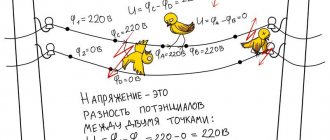
At the surface of the earth, the electrical potential is 0 volts. But you need to understand that this zero potential is a convention, a kind of reference point that many electricians stumble over when trying to explain the processes of electric current flow. Considering that a load is almost always included in the network, and it is unrealistic to distribute it evenly across phases, there is always a potential difference between the neutral (PEN) conductor and the ground, created by the resistance of the conductor and transition contacts. Accordingly, by touching the neutral conductor and standing on the ground, you will close the circuit and current will pass through you.
The neutral wire beats with current and the indicator lights up
This situation occurs due to various faults in electrical wiring or suitable lines. In this case, the neutral wire (or the one that the electrician considers as such) receives phase voltage .
The most common reasons why voltage appears on the neutral wire are:
- incorrect connection of electrical wiring in the input panel (phase and zero are reversed);
- neutral break;
- insulation violation.
It is impossible to see the presence of voltage at the neutral terminal without an indicator or tester, so checking whether an electric shock will occur if you touch the zero with bare hands can be life-threatening.
Is Zero electrocuted? Grounding in a multi-storey building: important details!
The zero or neutral wire serves to “channel” the electricity passing through the device. Just like the sewer system, the zero goes into the ground, that is, it is grounded in the basement of the building and must have a voltage equal to zero.
But it happens that the zero still receives an electric shock, especially in old houses. Why is this dangerous and how to eliminate it - let's figure it out!
Bus in the basement and electricians from the housing office: the root of the problem
Electricity in a multi-storey building is supplied through a thick cable - from a substation, which is usually located nearby. In the basement, this cable enters the ASU - a tall electrical cabinet with two bus sections, switches and powerful circuit breakers.
The buses in the ASU are divided into two types: neutral and grounding. In this cabinet they are connected to each other, as well as to the building grounding. Good contact on this bus is a guarantee that there will be no voltage at zero, and grounding, if there is one in the house, works as it should.
And now a small subtlety that only pros know about. The wires are attached to the copper bus using bolts and nuts. In order to eliminate the loosening of the nut, a split spring washer is placed between it and the tire. This washer puts pressure on the nut, preventing it from unwinding when the tire heats up (in the morning and evening - at the highest load) and cools down (in the middle of the day and at night).
If suddenly a short circuit occurs in the riser and the powerful automatic switch in the ASU is switched off, the tire will heat up much more than normal for a split second. According to the regulations, after each such case, electricians must tighten all the nuts on the tires. Do you think they do this? The question is rhetorical.
Month after month, year after year, the nuts on the ASU tires become increasingly loosened, begin to rust and oxidize, and the zero, naturally, becomes more and more dangerous to touch. Sooner or later, the neutral wire burns out, the voltage in the riser jumps to 380 Volts and a lot of expensive equipment for apartment owners becomes unusable.
The shield is repaired, especially competent victims are paid compensation and everything starts from the beginning.
What to do? Two Key Tips
The following can be advised to apartment owners.
- protect yourself from electric shock - install an RCD with a current of 30 mA on all sockets;
- protect devices from zero burnout and overvoltage using a “useemka” - an overvoltage protection relay;
- “get” your management company so that the house’s electrics (ASU and risers) are brought to normal condition - and if that doesn’t help, contact higher authorities, for example the housing inspector, or using online services such as Dobrodel.
I hope this article was useful, if so, like and share the article on your social networks - your friends will thank you for it!
Three-phase circuits are a type of sinusoidal current circuits, and, therefore, all previously discussed methods of calculation and analysis in symbolic form fully apply to them. It is convenient to analyze three-phase systems using vector diagrams, which make it possible to quite simply determine phase shifts between variables. However, a certain specificity of multiphase circuits introduces characteristic features into their calculation, which, first of all, concerns the analysis of their operation in symmetrical modes.
Calculation of symmetrical operating modes of three-phase systems
A polyphase receiver and a polyphase circuit in general are called symmetrical,
if in them the complex resistances of the corresponding phases are the same, i.e.
If . Otherwise they are asymmetrical.
The equality of the modules of the indicated resistances is not a sufficient condition for the symmetry of the circuit. So, for example, the three-phase receiver in Fig. 1a is symmetrical, but in Fig. 1, b – no, even if: .
If a symmetrical three-phase generator voltage system is applied to a symmetrical three-phase circuit, then a symmetrical current system will take place in it. This mode of operation of a three-phase circuit is called symmetrical.
In this mode, the currents and voltages of the corresponding phases are equal in magnitude and are shifted in phase with respect to each other by an angle.
As a result of this, the calculation of such circuits is carried out for one - base
- phase, which is usually taken to be phase A. In this case, the corresponding values in other phases are obtained by formally adding a phase shift to the argument of the variable phase A while maintaining its modulus unchanged.
So for the symmetrical operating mode of the circuit in Fig. 2, and with known line voltage and phase resistances we can write
,
where is determined by the nature of the load.
Then based on the above
;
.
Complexes of linear currents can be found using the vector diagram in Fig. 2, b, from which it follows:
When analyzing complex circuits operating in symmetrical mode, calculations are carried out using two main techniques:
All triangles are replaced with equivalent stars. Since the triangles are symmetrical, then in accordance with the triangle-star transformation formulas.
Since all the original and newly obtained load stars are symmetrical, the potentials of their neutral points are the same. Therefore, without changing the operating mode of the circuit, they can be (mentally) connected by a neutral wire. After this, the base phase (usually phase A) is isolated from the circuit, for which a calculation is carried out, based on the results of which the corresponding values in other phases are determined.
Let, for example, for a given phase voltage it is necessary to determine the linear currents in the circuit in Fig. 3, all resistances in which are known.
In accordance with the specified methodology, we select the calculated phase A, which is presented in Fig. 4. Here , .
Then for the current we can write
,
and correspondingly .
Calculation of asymmetrical operating modes of three-phase systems
If at least one of the symmetry conditions is not met, an asymmetrical operating mode occurs in a three-phase circuit. Such modes, in the presence of only a static load in the circuit and neglecting the voltage drop in the generator, are calculated for the entire circuit as a whole by any of the previously discussed calculation methods. In this case, the phase voltages of the generator are replaced by corresponding sources of EMF. It can be noted that since in multiphase circuits, in addition to currents, node potentials are usually also of interest, the method of node potentials is most often used to calculate complex circuits. To analyze asymmetrical operating modes of three-phase circuits with electrical machines, the method of symmetrical components is mainly used, which will be discussed below.
For given line voltages, three-phase circuits are most easily calculated when connected in a triangle. Let in the diagram in Fig. 2,a. Then, for known complexes of linear voltages, in accordance with Ohm’s law
; ; .
Based on the found phase currents of the receiver, the linear currents are determined based on Kirchhoff’s first law:
.
Usually in practice, it is not the complexes of linear voltages that are known, but their modules. In this case, it is necessary to preliminarily determine the initial phases of these stresses, which can be done, for example, graphically. To do this, taking , based on the given voltage modules, we build a triangle (see Fig. 5), from which (by measuring) we determine the values of angles a and b.
Then
The required angles a and b can also be found analytically based on the cosine theorem:
When the generator and load phases are connected in a star and there is a neutral wire with zero resistance, the load phase voltages are equal to the corresponding voltages on the source phases. In this case, phase currents are easily determined by Ohm’s law, i.e. by dividing the known voltages on the consumer phases by the corresponding resistances. However, if the resistance of the neutral wire is high or there is no neutral wire, a more complex calculation is required.
Consider the three-phase circuit in Fig. 6, a. With a symmetrical supply and an asymmetrical load, in the general case it will correspond to a vector voltage diagram (see Fig. 6,b), in which the neutral points of the source and receiver occupy different positions, i.e. .
The potential difference between the neutral points of the generator and the load is called the neutral point bias voltage
(usually it is assumed that ) or simply
the neutral bias voltage.
The larger it is, the stronger the asymmetry of phase voltages at the load, which is clearly illustrated by the vector diagram in Fig. 6, b.
To calculate the currents in the circuit in Fig. 6,a it is necessary to know the neutral bias voltage. If it is known, then the voltages on the load phases are equal to:
.
Then for the desired currents we can write:
.
The relationship for the neutral bias voltage, written based on the nodal potential method, has the form
| . | (1) |
In the presence of a neutral wire with zero resistance, and from (1). If there is no neutral wire. With a symmetrical load, taking into account the fact that , it follows from (1) .
As an example of analyzing the asymmetrical operating mode of a circuit using relation (1), we determine which of the lamps in the circuit in Fig. 7 with direct phase rotation of the source will burn brighter if.
Let us write down the expressions for the complex resistances of the load phases:
Then for the neutral bias voltage we will have
Load phase voltages (hereinafter, the index N for source phase voltages is omitted)
Thus, the light bulb will burn brightest in phase C.
In conclusion, we note that if, when connecting to a star, linear voltages are specified (which is usually the case in practice), then taking into account the fact that the sum of the latter is zero, they can be uniquely specified using two sources of emf, for example, and . Then, since in this case , relation (1) is transformed into the formula
| . | (2) |
Literature
- Fundamentals
of circuit theory: Textbook. for universities / G.V. Zeveke, P.A. Ionkin, A.V. Netushil, S.V. Strakhov. –5th ed., revised. –M.: Energoatomizdat, 1989. -528 p. - Bessonov L.A.
Theoretical foundations of electrical engineering: Electric circuits. Textbook for students of electrical engineering, energy and instrument engineering specialties of universities. –7th ed., revised. and additional –M.: Higher. school, 1978. –528 p.
Test questions and tasks
- Which polyphase receiver is symmetrical?
- What mode of operation of a three-phase circuit is called symmetrical?
- What is the specificity of calculating symmetrical operating modes of three-phase circuits?
- Using what techniques is a three-phase symmetrical circuit reduced to a calculated single-phase one?
- What is neutral bias voltage and how is it determined?
- How can you determine complexes of linear voltages if their modules are given?
- What does a neutral wire provide with zero resistance?
- In the circuit in Fig. 6,a; ; ; . Line voltage is 380 V.
- In the diagram of the previous task; . The rest of the parameters are the same.
- In problem 8, the neutral wire is broken.
- In problem 9, the neutral wire is broken.
Determine the current in the neutral wire.
Answer: .
Determine the current in the neutral wire.
Answer: .
Determine the phase voltages at the load.
Answer: ; ; .
Determine the phase voltages at the load.
Answer: ; ; .
What is a zero break?
To fully answer this question, it is necessary to provide examples of the normal operation of a three-phase power supply input circuit. As an example, we will give a simplified version with an input for a floor distribution board.
Scheme 1. Normal operation of the system
As can be seen from the figure, each of the apartments on the floor is powered from a separate phase (L1 - L3) and a common zero. Which forms a phase voltage of 220 volts (L1N=L2N=L3=220 V) in the household network of each apartment. In this case, a TN-CS power supply circuit is used, where a PE grounding bus is used, connected to the neutral in the building switchgear. The above system is balanced, since the load current in the phase wires is summed through the zero line, which reduces the likelihood of phase voltage imbalance.
Note that it is quite difficult to completely eliminate this phenomenon, since the load resistance at each phase may vary. For example, in apartment_1 the air conditioner and washing machine are turned on, in apartment_2 the owner turned on the boiler and electric stove, and in apartment_3 there are no residents and all household appliances are unplugged. As a result, voltage asymmetry will occur in a three-phase power system.
Now let's look at the network operation in abnormal mode, when the zero burns out.
Phase short circuit to zero
It often happens that due to damage to the wiring and insulation, a phase is short-circuited to zero. Of course, in this case the circuit breaker should trip.
However, if the wires are too long and the rating of the machine is incorrectly selected, this often does not happen, which leads to other, no less dangerous problems. Therefore, most often this is still damage to the phase wire in the wall, through which the current goes to zero and it begins to shock.
How to protect yourself?
Having learned about the danger posed by the loss of zero, we suggest considering options for protecting against this phenomenon:
- You need to start with proper installation of electrical wiring. If it is planned to use a three-phase power supply circuit to power the facility, then it must be calculated in such a way as to minimize the likelihood of phase imbalance. That is, it is necessary to systematically distribute the load on each line.
- Devices that balance the load on each phase should be used in network management. Moreover, ideally, this work should be carried out without the involvement of operators, that is, it should be performed automatically when the zero is broken.
- It should be possible to quickly change the consumer connection scheme. This allows adjustments to be made if at the design stage the load on each section was not properly taken into account or the power consumption increased due to the commissioning of new facilities. That is, if a critical situation arises, it must be possible to change the power. An example is when an apartment building is transferred to a line with a higher load to “dilute” the phase imbalance that occurs when the zero is broken.
In the above options, we considered protection against distortions on a global scale; the end user can provide the required level of protection much easier. To do this, it is enough to install a voltage control relay, in which you indicate the permissible minimum and maximum levels. As a rule, this is ±10% of normal.
Phase short circuit to zero
If the insulation of the supply cable is damaged, the neutral and phase conductors may short-circuit between themselves.
This is a short circuit mode and in this case the circuit breaker should turn off, however, with a large length of wires and, accordingly, high resistance of the current-carrying wires, the force does not exceed the setting value of the magnetic release of the circuit breaker, especially if it was selected incorrectly.
In this case, the wires will become very hot, the electric meter will begin to take into account the electricity spent in the shorted wires, and phase voltage will appear in the neutral wire.
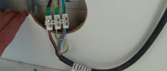
Why does the neutral wire get hot and is it dangerous?
Most often, the zero is heated in the panel at the entrance to the house or other distribution board. This could be heating in the terminal block on the input circuit breaker. This phenomenon also occurs if you have automatic or fused plugs installed, but in this case there are more places that can get hot. Here the screw terminals for connecting the wire and the thread (base) of the plug, as well as other connections, can heat up.
In simple words, there are three factors why the neutral wire or terminal heats up:
- The load is too high.
- Poor contact due to loose wires.
- Poor contact due to oxides or carbon deposits.
If the terminals are covered with carbon deposits, then an avalanche-like process of worsening the situation occurs. For example, carbon deposits appeared due to poor crimping or short-term overloads of the wiring, as a result of which the contact resistance increased. Any resistance heats up when current flows through it, and because of this heating, carbon deposits become even larger. Let's look at each of the reasons using examples of situations and their solutions.
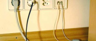
Important! Before performing any work on the electrical wiring, you must turn off the power supply. If it is not possible to do this, then use an indicator screwdriver to make sure that it is zero and not phase. Also, if you disconnect the neutral wire, but do not disconnect the phase, and at the same time at least one of the light switches or electrical appliances is connected to the network, then you will have “two phases”, that is, a life-threatening phase potential will appear on the neutral conductor.
Detecting a bad contact in a machine
Most models use screw terminals to connect wires to the circuit breaker. In the photo below you see the consequences of a bad connection in the machine:
To fix it, you just need to remove the wire and clean it of oxides and carbon deposits, and then clean the terminal block in any way:
- It is most convenient to use a small needle file; it will fit perfectly into the terminal block.
- If you don’t have a file, you can scrape off the carbon deposits with the tip of a slotted screwdriver of a suitable size or an awl.
After this, you need to tighten the screw well and clamp the wire, check that it does not dangle. If the zero on the machine was heated for a long time, then its contacts could be damaged. If after cleaning the contacts the heating does not disappear, then replace the machine completely. In a difavtomat, the reasons for heating the zero and eliminating it are similar.
Heating the zero plug
Usually a safety plug is set to zero, but you can often find an automatic plug; in principle, this is a functional analogue of an automatic machine. In the picture below you see the plug and its cartridge (holder) into which it is screwed. In this case, there are two possible places of heating - the thread of the plug holder and the terminal blocks to which the conductive wires are connected.
Pay attention to the surface of the holder: if it is cloudy and oxidized, this may be the reason that it is heating up, which can knock out plugs, then you need to clean it with a file or sandpaper. They just need to be cleaned, just like the screw terminals.
In the socket the zero heats up for the same reasons of poor contact.
Other causes of heating
Wires and contacts, as already mentioned, can heat up due to the increased load. There are three possible problems here:
The zero in the meter rarely gets warm; it is used there only for measurements.
Why is zero heating dangerous?
If the zero heats up, it can burn out. In a single-phase network this is practically not dangerous; in the worst case, a zero break will simply occur and two phases will appear in the socket, as described above, and accordingly your wiring will not function. If the neutral wire in a three-phase network burns out, for example at the entrance electrical panel, a phase imbalance will occur. As a result, the voltage in each phase can significantly exceed the nominal 220 volts, which can cause your household appliances and other electrical appliances to fail.
Heating also occurs during twisting, especially if aluminum is twisted directly with copper, in which case you need to use terminal blocks or a bolted connection. In this case, direct contact of copper and aluminum is eliminated by placing a washer between them.
Now you know why the zero in the electrical wiring heats up and how to eliminate this such a dangerous phenomenon. If you detect excessive heating, immediately begin to search for the cause that caused the emergency, or call an electrician, because further developments could be disastrous!