A rheostat is a variable resistor, the electrical resistance of which between its moving contact and the terminals of the resistive element can be changed mechanically (defined according to GOST 21414-75).
A rheostat is a type of potentiometer with two terminals instead of three. It is a so-called control element in electrical circuits.
An important advantage of a rheostat is that it can be used to change the electrical resistance in a circuit without breaking it.
Rheostat operating principle
The operating principle of the device is based on a stepwise or smooth change in resistance. This function is achieved by changing the position of the slide contact, which includes the necessary part of the high-resistance material in the circuit. An excellent visual example is the training rheostat. In it, nichrome wire is wound on a horizontal ceramic rod. On top of the conductive rod there is a movable slider with contact plates touching the winding. In the initial position, all the wire is included in the circuit and the resistance of the rheostat is at its maximum. By moving the slider, part of the wire is eliminated from the circuit, as the current passes through the part of the wire, and then along the path of least resistance through the contact plates and the conductive rod. Thus, a rheostat in an electrical circuit allows you to change the resistance, making it smaller or larger.
Rheostats used in electrical engineering have a more compact ring design, that is, the winding is made on a ring base, and the slider in the form of a rotating mechanism (slide) is fixed in the center of the ring. Variable step resistors are a set of fixed resistors connected in series in a circuit. In this case, a switch is added to the circuit, which, depending on the position, removes the current from a certain contact between the resistors.
Why does a rheostat need to be connected in series in an electrical circuit?
To connect a rheostat in a circuit, we must connect it in series and not in parallel. Electric current is known to flow along the path of least resistance. Therefore, when faced with a choice between a path with less resistance and a path with more resistance, he always chooses the lesser one.
A rheostat, as we already know, is a device with a variable resistance value. When we connect it to a parallel path, that path gets a little more resistance than the other available path. When current flows in an electrical circuit, electrons never take a parallel path but flow straight along a series path. Therefore, the rheostat will not work at all in this case.
How is a rheostat indicated in the diagrams?
A rheostat in diagrams is designated as a resistor with an arrow. With this designation, it is easy to understand that when the slider moves to the right, the resistance of the rheostat will decrease, and when moved to the left, it will increase.
Main types of rheostats
- According to the conductor material: wire made of alloys with high resistivity (nichrome, rheotan, constantan, manganin, nickel);
- non-wire made from sintered non-metallic conductive materials (most often graphite and carbon-based composites), including film
- volumetric
- for smooth adjustment: flux chords in the form of a straight piece of wire stretched onto the frame with a movable contact. As a rule, the frame has a scale, and the flux chord is graduated in Ohms/(unit of length).
, in which the role of a slider is played by a wheel made of conductive material moving along the surface of a dielectric drum with wire wound on it.
- plug-in, in which adjustment is carried out by moving the plug into one of the sockets;
- linear (in the USSR and the Russian Federation - group A)
Purpose of rheostats
According to their purpose, rheostats are divided into the following types:
- starting ones, used to reduce the starting current when starting the electric motor;
- ballasts, used primarily in DC motors, as well as with alternating voltage in the case of an asynchronous electric motor with a wound rotor;
- load, creating resistance in the electrical circuit;
- ballast, necessary to absorb excess energy that occurs, for example, when braking an electric motor.
A special type of rheostat is a potentiometer. This is a voltage divider based on a variable resistor. Thanks to it, electronic circuits can use different voltages without using additional transformers or power supplies. Adjusting the current strength using a rheostat is widely used in radio engineering, for example, to change the volume of a speaker.
Rheostat-based sensors
The position of the slider in the PC determines the magnitude of voltage and current in the operating electric current circuit. Making a sensor based on a rheostat is not difficult. The phase and zero of the power supply are supplied to the toroidal variable resistance, and the changed phase from the resistor and zero are output.
Today, outdated devices have been replaced by optical and magnetic analogues. Sensors based on variable resistors continue to be widely used in radio engineering. These are tuning resistances for volume controls and other options.
By turning the volume control knob of the radio device, move the slider along the graphite disk. The resistance of the circuit and the power of the sound signal depend on its position.
Operating principle
The operating principle of all rheostats is similar. The slider rheostat has the simplest design and visually clear principle of operation. It is connected to the circuit through the lower and upper terminals. The design is made in such a way that the current does not pass across the turns, but through the entire length of the wire selected by the slider. This occurs due to reliable insulation between the conductors.
The rheostat has the ability to operate in potentiometer mode. To do this, when making a connection, you must use all three terminals. The bottom two are used as an entrance. They are connected to a voltage source. The top and one of the bottom terminals are output. When you move the slider, the voltage between them is adjusted.
Rheostat used as a voltage divider
In addition to the potentiometer, a ballast mode of operation of the rheostat is also possible, when it is necessary to create an active load for energy consumption. In this case, it is necessary to take into account what scattering abilities the device has. Excessive heat can damage the device, so it is recommended to connect the rheostat to the network, having previously calculated the power dissipation and, if necessary, ensure sufficient cooling.
Types of rheostats
What is electrical resistance
The main three types of rheostats:
- toroidal rheostat;
- lever type;
- plug RS.
Toroidal rheostat
The PC winding is a toroidal structure, the upper surface of which forms a contact track. The rotary contactor rotates around its axis, touching the winding. The toroidal coil ensures continuity of the electrical circuit during rotation of the slider.
This feature of variable resistance is used in urban electric transport. Continuous changes in current and supply voltage of the electric motor ensure smooth movement of the vehicle. If the device breaks down, it cannot be repaired. The device will need to be replaced with a new rheostat.
Lever type
Unlike the toroidal model, a lever rheostat changes the value of current resistance in jerks. The lever, acting as a contactor, moves from one contact to another. The device contains several resistor lines with a certain resistance. The lever slider simultaneously operates as a switch on one line and a switch on another resistor.
Plug-in PCs
Like the lever type PC, plug devices regulate the resistance of the electrical circuit in steps. The only difference is that the transition from one mode to other current parameters occurs without breaking the circuit. When the next plug is removed, the energy flow is redirected through a certain resistor.
Types of units
Rheostats with an external design in the form of a torus are very popular. Their main area of application is electric transport (trams) and the industrial sector. Adjustment is carried out by moving the slider in a circle. The movement of such a part is carried out along windings that are located toroidally.
The device, made on the principle of a torus, modifies the resistance practically without breaking the circuit. Its opposite is a lever-type unit. The operating principle of such a rheostat is based on the fact that the resistors are mounted on a special frame, they are selected using a special lever. Any switching causes a break in the circuit.
Schemes that use a lever device do not have smooth resistance adjustment. Any switching entails a progressive change in indicators in the network. As for the discreteness of steps, it depends on the adjustment range and the number of resistors present on the frame.
Another type is plug-in rheostats, with the help of which stepwise resistance adjustment is carried out. The main difference is changing parameters within the network without first breaking the circuit. When the plug is applied to the jumper, the majority of the current flows without resistance. Redirecting the current to the resistor is done by pulling out the plug.
Liquid and lamp devices belong to specific types of rheostats. Due to the presence of certain disadvantages, they have a narrow, specialized scope of application:
- Liquid-type devices are used in explosive areas as engine control parts.
- Lamp products are characterized by low accuracy and reliability. Often used in educational institutions in physics lessons, laboratories, and research centers.
How the device is connected to the network
The device is connected to the circuit in two ways: in series and in parallel. When connected in series, the resistance of the equipment adds up. The total resistance will be greater than any individual resistance.
The diagram of electrical circuits, where rheostats with parallel connection are designated, looks like this:
With such a connection, the reciprocal values of the resistance are added, i.e. The total conductivity consists of the conductances of each component.
The presented drawings are intended for the simplest equipment. The more elements they include, the more complex the device created on their basis.
- Why is a rheostat used in an electrical circuit?
- Cable insulation resistance standards - table
- Instructions for rewinding electric motors with your own hands at home
Rheostat device
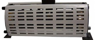
The rheostat device does not pose any difficulties for an experienced physicist and is a ceramic hollow cylinder with a metal winding, the ends of which are connected to special contacts, called terminals, located on both sides of the ceramic cylinder. A material with high resistivity is used as a winding, due to which even a small change in length reflects a change in resistance. Along the cylinder there is a metal hose on which a moving contact is attached, which is called a slider.
The ceramic cylinder inside is empty so that the device is cooled when electricity passes through it. For safety, a number of devices have a special casing that hides all the insides of the mechanism.
Types of rheostats according to the material of their manufacture
What is a throttle
The main element that determines the operating principle of a rheostat is the material from which it is made. In addition, when current passes through the device, it must be cooled: air or liquid. Air cooling occurs thanks to a hollow cylinder and is applicable in all devices. Liquid cooling is used only for rheostats made of metal. Cooling occurs due to complete immersion in liquid or individual parts of the device. Liquid rheostats can be water or oil.
The following rheostats can be distinguished based on the material of manufacture:
- Metal rheostats with air cooling are the most common, since they are applicable in various fields and for various devices; the resistance in them can be constant or stepped. The advantages of such structures are their compact size, fairly simple design, and affordable price. Metal liquid rheostats are a vessel filled with liquid. Steel, cast iron, chromium, nickel, iron, etc. can be used as manufacturing materials;
- Liquid rheostats are used to regulate current strength;
- Ceramic – applicable for relatively light loads;
- Coal ones are currently used only in the industrial sector and are a series of coal washers compressed together using springs. The resistance of this type of rheostat changes by changing the compression force of the springs.
Application of rheostats
When wondering why this device is needed in everyday life, you can get a banal answer: not a single modern TV can do without a rheostat. Thanks to this device, the volume level is adjusted, and it is also associated with the ability to switch channels.
As you can see, this is a truly universal and indispensable component. It is worth emphasizing that there are many types of rheostats, depending on their main purpose. Today, the rheostat is used in industry, in the automotive industry, and in modern electronic technology. It is widely used in radio engineering and various types of electric motors. Failure of the rheostat can damage the entire electrical system.
The meaning of the word Rheostat according to the Brockhaus and Efron dictionary:
Rheostat is the name of a device used to measure the electrical (or galvanic) resistance of a conductor. The device was first described under this name by Wheatstone in 1843. A similar device (agometer), independently of Wheatstone, was constructed by the Russian academician Jacobi. This latter was then improved by E. H. Lenz. The measurement method using these instruments is based on the introduction of a thin nickel-silver wire of a known length into a given galvanic circuit. This wire is wound around a marble cylinder, with one end communicating with the metal axis of the cylinder. When the cylinder rotates, either part of the wire is wound onto another metal cylinder (Wheatstone), or a metal wheel moves along the wire (Jacobi), or the cylinder itself moves along its axis, and the wheel remains in place (Lenz). N.A.G.
Classification of resistors
Resistors differ not only in their ability to adjust resistance. They can be made from different resistive materials, have different numbers of contacts, and have other features.
By type of resistive material
The elements can be wire, non-wire or metal foil. High-resistance wire is a feature of a wire element; alloys such as nichrome, constantan or nickel are used for its manufacture. Films with increased resistivity are the basis of non-wire elements. Metal foils use special foil. Now let's find out what resistors are made of.
Semiconductor design
Non-wire are divided into thin-layer and composite, the thickness of the former is measured in nanometers, and the latter in fractions of a millimeter. Thin-layers are divided into:
- metal oxide;
- metallized;
- borocarbons;
- metal-dielectric;
- carbonaceous.
Composite ones, in turn, are divided into volumetric and film. The latter can be with an organic or inorganic dielectric. To understand whether a resistor has polarity, you should know that their sides are identical.
By purpose resistance
Permanent and variable semiconductors also have some differences in characteristics. Permanent ones are divided into general and special purpose conductors. The latter may be:
- high frequency;
- high voltage;
- high-megaohm;
- precision.
Such parts are used in precision measuring instruments; they are particularly stable.
Variable resistors can be divided into trimming and adjusting. The latter can be with a linear or nonlinear functional characteristic.
By number of contacts
Depending on the purpose of the resistor, it may have one, two or more contacts. The contacts themselves are also different, for example, for SMD resistors it is a contact pad, for wire resistors it is a special wire composition. There are metal film resistors with quantum point contacts, and in variables they are moving.
Different number of contacts on elements
Other
Resistors differ in the shape and type of resistance, as well as in the nature of the dependence of the resistance value on voltage. The description of the dependence of a quantity can be linear or nonlinear. Using the element is simple, the capacity is indicated on the body, minus and plus are the same.
Resistors may or may not be sealed against moisture, and the housing may be varnished, vacuum sealed, sealed, pressed into plastic, or compounded. Nonlinear ones are divided into:
- varistors;
- magnetoresistors;
- photoresistors;
- posistors;
- strain gauges;
- thermistors.
They all perform their specific function, some change resistance based on temperature, others on voltage, and others on radiant energy.
Trimmer resistors
Trimmer resistors are a type of variable. The brush contact assembly of such resistors is adapted to control a screwdriver. The symbol for a tuning resistor (Fig. 12) clearly reflects its purpose: it is, in fact, a constant resistor with a tap, the position of which can be changed.
Rice. 12. Appearance and designation of trimming resistors.
The general designation of a tuning resistor differs in that instead of a control sign, a tuning control sign is used.
What is the difference between a resistor and a rheostat, a transistor?
A rheostat is an electrical device. Which is capable of regulating current and voltage in an electrical circuit. In general, this is an analogue of a variable resistor. It includes a conductive element and a resistance regulator. You can influence the change in the indicator smoothly, and if desired, this can be done in steps. In standardization, rheostats are variable, regulating and tuning resistors.
A transistor is a device for controlling electric current. Essentially, it amplifies the current and can control it, and the conductor regulates the resistance in the network. Externally, the two elements differ significantly from each other. The resistor is cylindrical in shape and colored, and the transistor is housed in a plastic or metal square housing.
Conclusions: conductors have the same functionality, but the transistor has different functionality. Also, a transistor is a polar element, and a resistor is non-polar. For this reason, it is possible to confuse two elements only if a person is completely far from electrical engineering and radio electronics.
A resistor is a necessary element in all microcircuits of modern electrical appliances. By providing resistance in the circuit, the semiconductor divides or reduces the voltage, so that various devices can operate from the network. Current resistance is measured in Ohms, and proper selection of semiconductor will ensure long-term operation of any electrical appliance. So we found out what a resistor is and what it is needed for, how it differs from a rheostat and a transistor, and how it is indicated on the diagrams.
General information
Electric current is the movement of free charged particles under the influence of an electromagnetic field. Any substance consists of atoms that form a crystal lattice using covalent bonds. When an electric current flows through a conductor, its particles interact with the nodes of the crystal lattice. Charge carriers have kinetic energy (Ek), which depends on the mass of the particle (m) and its speed (V3). It is determined by the formula: Ek = m * sqr (V3) / 2 .
When particles collide with nodes of a crystal lattice, a complete or partial transfer of energy to the atom occurs.
However, the energy potential of the free charge carrier is restored, since it is constantly affected by the electromagnetic field. The process of interaction of particles with atoms is repeated a certain number of times until the influence of the electromagnetic field stops or the particle passes completely through the conductor. This physical phenomenon is called electrical resistance or conductivity. The last value is the reciprocal of the resistance. Resistance is designated by the letter “R”, and conductivity by “G”.
The unit of resistance is Ohm. It is calculated using certain formulas or measured with an electronic measuring device called an ohmmeter.
Physical dependence
The value of R depends on the number of free charge carriers, the number of which is determined based on the electronic formula of the substance. It can be determined from the periodic table of chemical elements by D.I. Mendeleev. Substances are classified according to conductivity as follows: conductors, semiconductors and insulators (non-conductors).
Conductors include all metals, electrolytes and ionized gases.
In metals, charge carriers are free electrons, in electrolytes - anions and cations, and in ionized gases - electrons and ions. Semiconductors are capable of conducting electrical current under certain conditions. In semiconductors, free electrons and holes are charge carriers. Insulators or dielectrics are not capable of conducting electricity because there are no free charge carriers in their structure.
The quantity that determines the type of material and its ability to conduct is called resistivity (p). There is also an inverse value regarding resistivity. It is called conductivity (σ) and is related to p by the following formula: p = 1/σ . When performing calculations, it is necessary to take into account the dependence of the electrical resistance of the material on other physical quantities or factors, which include the following:
- geometric components;
- electrical quantities;
- temperature indicators.
These three groups of factors must be taken into account when manufacturing rheostats, resistors and other resistive load elements. During repair and design of devices, all factors should also be considered, since incorrect calculations can lead to failure of the radio equipment.
You may be interested in Single-phase automatic machine c16
Material geometry
The geometry of a conductor (semiconductor) includes its length (L) and cross-sectional area (S). The value of S can be calculated using an abstract algorithm that is suitable for all forms of conductors and semiconductors. It looks like this:
- Visually determine the shape of the cross-sectional figure (circle, rectangle or square).
- Find in reference books or the Internet a formula for finding the cross-sectional area of a figure.
- Measure the necessary geometric parameters (for example, diameter) and substitute them into the formula.
- Perform mathematical calculations.
If the conductor is stranded (consists of many conductors), then the cross-sectional area of one conductor should be calculated and then multiplied by the number of conductors. Based on everything, we can deduce the dependence of the resistance value on the type of substance, length and cross-sectional area of the conductor: R = p * L / S.
The physical meaning of the dependence is as follows: an electric current moves through a conductor, the type of which is determined by the parameter p, and its particles pass through a certain length L with a cross-section S (with a small cross-sectional area, more frequent collisions of electrons with nodes of the crystal lattice occur).
However, geometric parameters are not the only factors influencing the conductivity value of a material.
Influence of electricity parameters
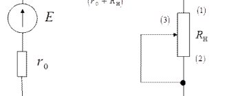
In order to take into account the influence of current and voltage on R, you should pay attention to Ohm's law. He has two formulations used for calculations: for the complete chain or its section. Ohm's law for a complete circuit shows the dependence of the current value (i) on the electromotive force (e) and the value of R, consisting of the sum of the internal (Rinternal) and external (Rexternal) resistances.
The variable Rinternal is the internal resistance of the power source (generator, battery, transformer, etc.). Rext is the resistance of all consumers of electrical energy and connecting wires. Ohm's law for a complete circuit connects all these quantities with the following relation: i = e / (Rexternal + Rinternal) . The value of Rext is determined by the formula: Rext = (e / i) - Rint .
For a section of a circuit, the relationship for finding the resistance is simplified, since the EMF and Rinternal are not taken into account. This law shows a directly proportional dependence of the current (I) on the voltage (U), as well as inversely proportional to the resistance value R: I = U / R. In some cases, these factors may not be enough for accurate calculations, since there is another dependence - the temperature indicators of the material.
Effect of temperature on conductivity
Resistivity affects the conductivity of a material, but it depends on temperature. To prove this hypothesis, you need to assemble an electrical circuit consisting of the following components: an incandescent lamp, a power source (12 V), a piece of nichrome wire and an ammeter. Any power source can be selected.
You might be interested in everything about phase-zero loops
It is important that the voltage value is not higher than the nominal value of the potential difference of the lamp, i.e. the battery is 12 V, and the lamp must also be 12 V. The circuit elements are connected in series. It is recommended to place a piece of wire on a refractory brick, since when electric current flows through the nichrome, it will heat up.
An ammeter is needed to monitor current values that will change over time. The lamp is a light “signaling device” that allows you to visually observe an increase in resistance. The brightness of its glow will gradually fade. When current flows through the circuit, Ohm's law is visually confirmed for a section of the circuit. As R increases, the current decreases. The dependence of resistivity p depends on the following variables:
- Table value of resistivity (p0), calculated at a temperature of +20 degrees Celsius.
- Temperature coefficient "a", which for metals is considered greater than 0 (a > 0), and for electrolytes - less than 0 (a < 0).
The tabulated value of p0 can be found from special electrical reference books or from the Internet. The dependence of p on temperature is described by the following relation: p = p0 * [1 + a * (t - 20)] . If necessary, you can substitute p into the formula for the dependence of R on length and cross-section: R = p0 * [1 + a * (t - 20)] * L / S.
It makes no sense to perform exact resistance calculations, but these features should be taken into account when manufacturing and repairing various devices.
Resistance should be measured with an ohmmeter, but professional radio amateurs recommend using a multimeter. It is combined and allows you to measure not only resistance, but also current and voltage. There are models that can measure frequency, test semiconductor devices, etc.
Cooling
Electricity, passing through a resistor, spends part of the energy to overcome the resistance of the conductor, which is converted into heat. If it is released excessively, the rheostat can overheat and become completely unusable.
For this reason, according to GOST, two cooling systems for variable resistors are used, these are:
- air;
- liquid.
Air cooling system
It is based on forced ventilation. For this purpose, blade and turbine fans are used. In a rheostat, the sensor measures the heating level of the device. When the permissible temperature threshold is reached, the sensor sends a signal to turn on the ventilation system. When the temperature drops, the fan turns off.
Liquid cooling
Liquid cooling of a high-power variable resistor is carried out using a sarcophagus, in the jacket of which mineral oil constantly circulates. It removes heat from the rheostat to the outside.
Variable resistor.
A variable resistor is a resistor in which the electrical resistance between the moving contact and the terminals of the resistive element can be changed mechanically.
Variable resistors, also called rheostats or potentiometers, are designed to gradually regulate current and voltage. They look like this:
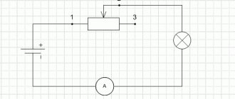
The difference is that a rheostat regulates the current in an electrical circuit, and a potentiometer regulates voltage. On radio circuits, variable resistors are designated by a rectangle with an arrow attached to their body.
In the diagrams, numbers 1 to 3 indicate the location of the resistor outputs.
You can adjust the resistance power of variable resistors by rotating a special knob. Those resistors in which the resistance of the resistor can be adjusted only with a screwdriver or a special hex key are called tuning variable resistors. They look like this:
Rheostats. Types and device. Operation and features
In many electronic devices, you need to change the current to control the volume of the sound. Let's consider a device (rheostats) with which you can change the current and voltage. The current strength depends on the voltage at the ends of the circuit section and on the resistance of the conductor: I=U/R . If you change the resistance of the conductor R , then the current strength will change.
Manufacturing materials
What is insulation resistance measurement and why is it important
Rheostats are divided into 4 types based on the type of material they are made of. These are carbon, metal, liquid and ceramic RS:
- Carbon devices include models where a graphite rod acts as a variable resistance.
- A metal example of execution can be slider rheostats. They have a variable resistor - a coil of metal wire.
- Liquid variable resistances are used to control the operation of electric motors in explosive atmospheres.
- Ceramic rheostats include toroidal devices. Their device is described above in the text.
Design and principle of operation
Before you understand how a rheostat is indicated on an electrical diagram, you need to know its configuration and operating principle.
The design of the device consists of:
- Ceramic tube (cylinder) – hollow inside to reduce temperature during the passage of electricity.
- Copper wire - wound around the tube, and its ends are brought out to the contacts.
- Metal rod - placed above the tube, there is a contact on one side of the component.
- A moving slider or contact is fixed to a rod.
Despite the release of many varieties, the operating principle of all devices is approximately the same. Connection is possible using terminals located on both sides of the tube. The current flows along the entire perimeter, depending on the location of the slider.
If it is located in the center of the device, then the current will only pass to the middle. If the slider is placed at the end, then the current passes completely, forming a high voltage. In most cases, only part of the plane is involved, i.e. The slider is not installed on the edge of the cylinder. The change in its location is proportional to the fluctuation in current strength.
Design and its features
Having determined what rheostats are intended for, you should take a closer look at their constituent side. Depending on the material used in production, the following installations are distinguished:
- ceramic - the peculiarity is that they are used at low power;
- metal - are widely used in various areas of human activity;
- coal - their main use in industry.
Important! Heat is removed by oil, water or air. If there is no way to dissipate heat from the working surface, liquid cooling is used. Heat transfer can be increased through the use of a fan and radiator.
Types of rheostats
A rheostat in the form of a torus changes resistance practically without creating a break in the circuit. In complete contrast to it is the lever view. The resistors are located on a special frame and are selected using a lever. Any switching is accompanied by a circuit break. In addition, in circuits with a lever rheostat there is no possibility of smoothly adjusting the resistance. All switchings lead to stepwise changes in network parameters. The discreteness of steps depends on the number of resistors on the frame and the control range.
Like lever rheostats, plug-in rheostats regulate resistance in steps. A distinctive feature is changing network parameters without breaking the circuit. When the plug is in the jumper, most of the current flows beyond the resistance. The number of possible inclusion options depends on the size of the store. Pulling out the plug redirects the current to the resistor.
Specific types include lamp devices and liquid rheostats. Due to a number of shortcomings, these devices are not widely used. Liquid rheostats can only be found in explosive environments, where they perform engine control functions. Tube ones can be found in laboratories and in physics lessons, since their reliability and accuracy are not sufficient for widespread use.
Resistor resistance designation
The minimum power dissipation of the resistor (from 0.05 to 5 W) is indicated by special signs placed inside the symbol (Fig. 3). Note that mm should not touch the contour of the resistor symbol.
Rice. 3. Designation of resistor power.
On the circuit diagram, the nominal resistance of the resistor is indicated next to the symbol (Fig. 4). According to GOST 2.702-7S, resistance from 0 to 999 Ohms is indicated by a number without a unit of measurement (2.2; 33, 120.), from 1 to 999 kOhm - by a number with a letter k (47 k, 220 k, 910 k, etc. ), over 1 megaohm - a number with the letter M (1 M, 3.6 M, etc.).
Rice. 4. Resistance designation for resistors on diagrams.
On domestically produced resistors, the nominal resistance, the permissible deviation from it, and, if dimensions allow, the rated dissipation power are indicated in the form of a full or abbreviated (coded) designation.
According to GOST 11076-69, resistance units in the coded system are designated by the letters E (ohm), K (kilo-ohm) and M (mega-ohm). So, resistors with a resistance of 47 Ohms are marked 47E, 75 Ohms - 75E, 12 kOhms - 12K, 82 kOhms - 82K, etc.
Resistances from 100 to 1000 Ohms and from 100 to 1000 kOhms are expressed in fractions of kilo-ohm and mega-ohm, respectively, and the corresponding unit of measurement is placed in place of zero and comma:
- 180 Ohm = 0.18 kOhm = K18;
- 910 Ohm = 0.91 kOhm = K91;
- 150 k0m = 0.15 MOhm = M15;
- 680 k0m = 0.68 MOhm = M68, etc.
If the nominal resistance is expressed as an integer with a fraction, then the unit of measurement is placed in place of the decimal point: 2.2 Ohm - 2E2; 5.1 kOhm -5K1; 3.3 MOhm - ZMZ, etc.
Coded letter designations are also established for permissible resistance deviations from the nominal value. The permissible deviation of ±1% corresponds to the letter P, ±2% to L, ±5% to I, ±10% to C, ±20% to B. Thus, the inscription on the body of the K75I resistor indicates a nominal resistance of 750 Ohms with a permissible deviation of ±5%; inscription MZZV - 330 kOhm ±20%, etc.
Adjustable resistors
Adjustable resistors - resistors whose resistance can be changed within certain limits are used as controls for gain, volume, tone, etc. The general designation of such a resistor consists of a base symbol and a control sign, and regardless of the position of the symbol in the diagram, an arrow indicating control , carried out in the direction from bottom to top at an angle of 45 degrees.
Adjustable resistors have relatively low reliability and limited service life. Who of the owners of a radio receiver or tape recorder has not had to hear rustling sounds from the loudspeaker after two or three years of operation when adjusting the volume?
The reason for this unpleasant phenomenon is a violation of the contact of the brush with the conductive layer or wear of the latter. Therefore, if the main requirement for a variable resistor is increased reliability, resistors with step regulation are used.
Such a resistor can be made on the basis of a switch with several positions, to the contacts of which constant resistance resistors are connected. The diagrams do not show these details, limiting themselves to depicting a symbol of an adjustable resistor with a step control sign, and if necessary, indicating the number of steps (Fig. 8).
Rice. 8. Image of the symbol of an adjustable resistor with a sign of step regulation.
Some variable resistors are made with one, two or even three taps. Such resistors are used, for example, in thin-compensated volume controls used in high-quality sound-reproducing equipment. Branches are depicted as lines extending from the long side of the main symbol (Fig. 9).
Rice. 9. Designation of a variable resistor with taps.
To regulate volume, timbre, recording level in stereophonic equipment, frequency in measuring signal generators, etc., dual variable resistors are used, the resistance of which changes simultaneously when the common axis is rotated (or the slider is moved). In the diagrams, they try to place the symbols of the resistors included in them as close to each other as possible, and the mechanical connection is shown either with two solid lines or one dashed line (Fig. 10, a).
Rice. 10. Appearance and designation of blocks with variable resistors.
If this cannot be done, i.e., the resistor symbols are at a great distance from one another, the mechanical connection is depicted with dashed line segments (Fig. 10.6). In this case, the belonging of the resistors to one dual block is also shown in the positional designation (R1.1 is the first - according to the diagram - the resistor of the dual variable resistor R1, R1.2 is the second).
There are also dual variable resistors in which each resistor can be controlled separately (the axis of one runs inside the tubular axis of the other). In this case, there is no mechanical connection that ensures a simultaneous change in the resistances of both resistors, therefore it is not shown on the diagrams (belonging to a dual resistor is indicated only in the positional designation).
In household radio equipment, variable resistors are often used, combined with one or two switches. The symbols of their contacts are placed on the diagrams next to the designation of the variable resistor and connected by a dashed line with a thick dot, which is depicted on the side of the rectangle, when moved to which the brush contact assembly (motor) acts on the switch (Fig. 11, a).
Rice. 11. Designation of a variable resistor combined with a switch.
This means that the contacts close when moving from a point, and open when moving towards it. If the resistor and switch symbols are distant from one another, the mechanical connection is shown by dashed line segments (Fig. 11.6).
Fixed resistors
At first, resistors were depicted on diagrams in the form of a broken line - a meander (Fig. 1, a, b), which indicated a high-resistance puncture wound around an insulating frame. As radio devices became more complex, the number of resistors in them increased, and to make drawing easier, they were depicted on diagrams in the form of a jagged line (Fig. 1c).
This symbol was replaced by a symbol in the form of a rectangle (Fig. 1, d), which began to be used to designate any resistor, regardless of its design and features.
Rice. 1. Fixed resistors and their designation.
Fixed resistors can have one or more taps from the resistive element. On the symbol of such a resistor, additional terminals are depicted in the same order as is the case in the resistor itself (Fig. 2). With a large number of taps, the length of the symbol can be increased.
Rice. 2. Fixed resistors with taps - designation.
The resistance of a fixed resistor, as the name suggests, cannot be changed. Therefore, if it is necessary to set a certain current or voltage in a circuit, then for this it is necessary to select individual elements of the circuit, which are often resistors. An asterisk * is placed next to the symbols of these elements in the diagrams - a sign indicating the need to select them when setting up or adjusting.
Sensors based on rheostats
The voltage, current in the operating circuit, the position of the slider in the rheostat and the resistance it provides are directly dependent.
This feature forms the basis of the rotation angle sensor. In such a device, a specific electrical quantity corresponds to a specific rotor position. Currently, such sensors are being replaced by improved optical and magnetic analogues. The reason for this is the instability of the dependence of resistance and angle in relation to the temperature effect. The gradual displacement of rheostat-type sensors is also due to the transition to digital, more convenient systems. Today, resistive meters are used in circuits where analog signals are present.
Knowing why electric rheostats are needed, one can easily explain their widespread use in the automotive industry, technology, and industry. Resistance is necessary for the operation of radio equipment; when starting electric motors, they are used in the form of an active load. The failure of a small device can lead to a failure of the entire system.
This is the importance of rheostats
Sensors based on rheostats
There are direct relationships between the position of the rheostat slider, its resistance, the current in the circuit and the voltage. These features form the basis of the rotation angle sensor. Each position of the rotor in such a device corresponds to a certain electrical quantity.
Gradually, such sensors are being replaced by magnetic and optical devices. This is due to the fact that the characteristic of the dependence of angle and resistance is immune to interference from the influence of temperature. The transition to digital systems also contributes to the displacement of rheostatic sensors. Resistive meters can only be found in circuits that use analog signals.
Types of rheostats
The type of rheostats depends on their main purpose:
- Starting rheostats are designed to start electric motors with direct or alternating current;
- Starter rheostats are not only designed to start DC motors, but also to regulate the current;
- Ballast rheostats, also called load rheostats, absorb energy that is necessary to regulate the load on electric generators, i.e. create the required resistance in the electrical network;
- Excitation rheostats are used in electrical machines to regulate direct and alternating current; they absorb excess energy;
- A special group includes rheostats designed to divide voltage; they are called potentiometers. They allow you to use different voltages in one device without using additional devices such as transformers and power supplies. In this case, the rheostat has 3 terminals, where the lower terminals are used for current input, and the upper and one lower terminals are used as output. The voltage is adjusted by moving the slider.
Thanks to the use of rheostats in electrical appliances and machines, there is a reduction in electrical current surges and motor overloads, this, in turn, increases the service life of electrical appliances.
The rheostat on the electrical diagram has its own special designation.
Why do you need a rheostat: the principle of operation of the unit, the main types, application in the circuit
A device that can cope with changes in resistance is usually called a rheostat. Structurally, it is represented by a set of resistors that are connected to each other in steps and can provide a continuous change in resistance. A separate category includes devices that provide smooth regulation without interrupting the network. To decide what a rheostat is needed for, you need to take a closer look at its features and operating principle.
The described devices are universal in use. Depending on their intended purpose, they are usually divided into the following types:
- Starters - most often used to equip DC motors. Such models are appropriate for asynchronous electric motors with alternating voltage, equipped with a wound rotor.
- Starting - their main purpose is to reduce the starting current that appears when starting the electric motor.
- Ballast - they provide rapid absorption of excess energy that occurs during sudden engine braking.
- Load - such products create the necessary resistance inside the electrical circuit.
Important! Rheostats are used as current limiters in the excitation windings of electric machines with direct current.
In this way, strong differences in electric current are equalized, as well as dynamic overloads, leading to damage to the drive and the entire mechanism connected to it. Providing suitable resistance at startup will extend the life of the commutator and brushes.
Potentiometers are included in a separate group. They are voltage dividers based on variable resistors. Such devices make it possible to use different voltages in electronic circuits without additional power supplies or transformers. Regulation of current strength by means of a rheostat is often used in the radio engineering field. A striking example of this is the change in volume in the speakers.
Operating principle
The described devices are similar in their functional purpose. Structurally and visually, the slider type rheostat is considered the simplest. It is connected to the circuit using a top and bottom terminal. The device is designed in such a way that current flows along the entire length of the wire, and not in the transverse direction of the turns. This is achieved thanks to the reliable insulation of the conductors.
Important! Most slider positions only use part of the rheostat. When changing the length of the conductor, the strength of the electric current in the working circuit is adjusted. In order to prevent premature wear of the coils, the slider is equipped with a sliding contact (wheel or graphite rod).
Often a rheostat is used to regulate a circuit instead of a potentiometer. In this case, it is connected using three terminals. At the bottom, two of them are the input, connected to the voltage source. One lower terminal and the upper free one are used as output. When the slider moves, the voltage can be easily adjusted.
The rheostat has the ability to operate in ballast mode, which may be necessary when creating an active load during energy consumption. In such a situation, it is recommended to take into account the dissipative capabilities of the unit used. If there is excess heat, the device will fail. When connecting to the electrical network, you need to correctly calculate the power dissipation of the rheostat and, if necessary, create sufficient and correct cooling.
Types of units
Rheostats with an external design in the form of a torus are very popular. Their main area of application is electric transport (trams) and the industrial sector. Adjustment is carried out by moving the slider in a circle. The movement of such a part is carried out along windings that are located toroidally.
The device, made on the principle of a torus, modifies the resistance practically without breaking the circuit. Its opposite is a lever-type unit. The operating principle of such a rheostat is based on the fact that the resistors are mounted on a special frame, they are selected using a special lever. Any switching causes a break in the circuit.
Schemes that use a lever device do not have smooth resistance adjustment. Any switching entails a progressive change in indicators in the network. As for the discreteness of steps, it depends on the adjustment range and the number of resistors present on the frame.
Another type is plug-in rheostats, with the help of which stepwise resistance adjustment is carried out. The main difference is changing parameters within the network without first breaking the circuit. When the plug is applied to the jumper, the majority of the current flows without resistance. Redirecting the current to the resistor is done by pulling out the plug.
Liquid and lamp devices belong to specific types of rheostats. Due to the presence of certain disadvantages, they have a narrow, specialized scope of application:
- Liquid-type devices are used in explosive areas as engine control parts.
- Lamp products are characterized by low accuracy and reliability. Often used in educational institutions in physics lessons, laboratories, and research centers.
Design and its features
Having determined what rheostats are intended for, you should take a closer look at their constituent side. Depending on the material used in production, the following installations are distinguished:
- ceramic - the peculiarity is that they are used at low power;
- metal - are widely used in various areas of human activity;
- coal - their main use in industry.
Important! Heat is removed by oil, water or air. If there is no way to dissipate heat from the working surface, liquid cooling is used. Heat transfer can be increased through the use of a fan and radiator.
Sensors based on rheostats
The voltage, current in the operating circuit, the position of the slider in the rheostat and the resistance it provides are directly dependent. This feature forms the basis of the rotation angle sensor. In such a device, a specific electrical quantity corresponds to a specific rotor position.
Currently, such sensors are being replaced by improved optical and magnetic analogues. The reason for this is the instability of the dependence of resistance and angle in relation to the temperature effect. The gradual displacement of rheostat-type sensors is also due to the transition to digital, more convenient systems. Today, resistive meters are used in circuits where analog signals are present.
Knowing why electric rheostats are needed, one can easily explain their widespread use in the automotive industry, technology, and industry. Resistance is necessary for the operation of radio equipment; when starting electric motors, they are used in the form of an active load. The failure of a small device can lead to a failure of the entire system. This is the importance of rheostats
Source: https://220v.guru/elementy-elektriki/dlya-chego-nuzhen-reostat-princip-ego-raboty-v-cepi.html