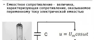
Capacitor in AC circuit
Direct current cannot exist in a circuit containing a capacitor. The movement of electrons is prevented by a dielectric located between the plates. But alternating current can exist in such a circuit, as evidenced by experience with a lamp (see figure below).
Even if such a circuit is actually open, but if alternating current flows through it, the capacitor is either charged or discharged. The current flowing when the capacitor is recharged heats the lamp filament, and it begins to glow.
Let's find how the current strength changes in a circuit containing only a capacitor, if the resistance of the wires and plates of the capacitor can be neglected (see figure above). The voltage across the capacitor will be equal to:
u=φ1−φ2=qC..
Let's take into account that the voltage across the capacitor is equal to the voltage at the ends of the circuit:
qC..=Umaxcos.ωt
Consequently, the charge of the capacitor changes according to the harmonic law:
q=CUmaxcos.ωt
Then the current strength, which is the time derivative of the charge, will be equal to:
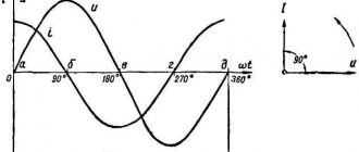
i=q´=−CUmaxsin.ωt=CUmaxcos.(ωt+π2..)
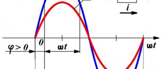
Consequently, current fluctuations are ahead of voltage fluctuations across the capacitor by π2.. (see graph below). This means that at the moment when the capacitor begins to charge, the current is maximum and the voltage is zero. After the voltage reaches its maximum, the current becomes zero, etc.
The amplitude of the current is:
Imax=UmaxCω
Let's assume that:
1Cω..=XC
We will also use the effective values of current and voltage. Then we get that:
Definition
I=UXC..
The value of XC, equal to the inverse product of the cyclic frequency and the electrical capacitance of the capacitor, is called capacitance . The role of this quantity is similar to the role of active resistance R in Ohm's law.
Note that during the quarter period when the capacitor is charged to its maximum voltage, energy enters the circuit and is stored in the capacitor in the form of electric field energy. In the next quarter of the period (when the capacitor is discharged), this energy is returned to the network.
Example No. 1. The maximum charge on the capacitor plates of the oscillatory circuit is qmax=10−6 C. The amplitude value of the current in the circuit is Imax = 10−3 A. Determine the period of oscillation (neglect losses due to heating of the conductor).
According to the law of conservation of energy, the maximum value of the energy of the electric field of the capacitor is equal to the maximum value of the magnetic field of the coil:
q2max2C..=LI2max2..
From here:
LC=q2maxI2max..
√LC=qmaxImax..
T=2π√LC=2πqmaxImax..=2·3.1410−610−3..≈6.3·10−3 (s)
What is a capacitor
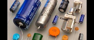
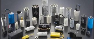
A capacitor is a two-pole device that has a constant or variable capacitance value and low conductivity. This is a circuit element that serves as an energy storage device that forms an electric field; passive electronic component of any connection. It contains several metal electrodes or plates, between which there is a dielectric. It can have a package, tubular, disk, cast sectional and roll design.
Read also: Value added tax (VAT)
Capacitor
The capacitor has a flat or cylindrical shape. A flat device consists of plates located relatively far apart from each other, and a cylindrical device consists of several hollow coaxial conducting cylinders with radii r1 and r2 (the main condition is r1 > r2).
Term from the textbook
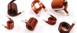
Inductor in an AC circuit
Let's assemble two electrical circuits consisting of an incandescent lamp, an inductor and a power source: in the first case, constant, in the second - alternating (see figures “a” and “b” below).
Experience will show that a lamp in a direct current circuit glows brighter compared to one connected in an alternating current circuit. This indicates that the current in the DC circuit is higher than the effective value of the current in the AC circuit.
The result of the experiment is easily explained by the phenomenon of self-induction. When the coil is connected to a constant current source, the current increases gradually. The vortex electric field, which increases with increasing current strength, slows down the movement of electrons. Only after some time does the current reach its maximum value corresponding to a given constant voltage.
If the voltage changes quickly, the current does not have time to reach its maximum value. Therefore, the maximum value of current in an AC circuit with an inductor is limited by the inductance. The greater the inductance and the greater the frequency of the applied voltage, the smaller the amplitude of the alternating current .
Let us determine the current strength in a circuit containing a coil whose active resistance can be neglected (see figure below). To do this, we will find the connection between the voltage on the coil and the self-induction emf in it.
If the coil resistance is zero, then the electric field strength inside the conductor at any time must be zero. Otherwise, according to Ohm's law, the current would be infinitely large. The field strength being equal to zero is possible because the strength of the vortex electric field →Ei generated by the alternating magnetic field at each point is equal in magnitude and opposite in direction to the strength of the Coulomb field →Ek created in the conductor by charges located at the terminals of the source and in the wires of the circuit .
From the equality →Ei=−→Eк it follows that the specific work of the vortex field (i.e. self-induction emf ei ) is equal in magnitude and opposite in sign to the specific work of the Coulomb field .
Considering that the specific work of the Coulomb field is equal to the voltage at the ends of the coil, we can write:
ei=−u
Let us recall that the strength of alternating current varies according to the harmonic law:
i=Imaxsin.ωt
Then the self-induction emf is equal to:
ei=−Li´=−LωImaxcos.ωt
Since u=−ei, the voltage at the ends of the coil is equal to:
u= LωImaxcos.ωt=LωImaxsin.(ωt+π2..)=Umax(ωt+π2..)
The voltage amplitude is:
Umax=LωImax
Consequently, voltage fluctuations on the coil lead current fluctuations by π2.., or current fluctuations lag behind voltage fluctuations by π2.., which is the same thing.
At the moment when the voltage across the coil reaches its maximum, the current is zero (see graph below).
But at the moment when the voltage becomes zero, the current strength is maximum in magnitude. The amplitude of the current in the coil is equal to:
Imax=UmaxLω..
Let us introduce the notation:
Lω=XL
We will also use the effective values of current and voltage instead of amplitudes. Then we get:
Definition
I=UXL..
The quantity XL , equal to the product of the cyclic frequency and inductance, is called inductive reactance . Inductive reactance depends on frequency. Therefore, in a direct current circuit in which there is no frequency, the inductive reactance of the coil is zero.
Example No. 2. A coil with inductive reactance XL = 500 Ohm is connected to an alternating voltage source whose frequency is ν = 1000 Hz. Effective voltage value U = 100 V. Determine the amplitude of the current Imax in the circuit and the inductance of the coil L. Neglect active resistance.
The inductive reactance of the coil is expressed by the formula:
XL=Lω=2πνL
From here:
Since the voltage amplitude is related to its effective value by the relation Umax=U√2, then for the current amplitude we obtain:
Formula
The capacitor charge current is found using the formula presented below. It is measured in farads, which is equal to a coulomb or volt.
Formula for finding the charge of a capacitor
In general, this is an element of the electrical network that accumulates and stores voltage in it. It comes in different types and sizes, for example, electrolytic, ceramic and tantalum. It consists mainly of several conductive plates with a dielectric. Its capacity depends on the size of the dielectric and the filler between the plates. Charges using electricity. The capacitor charge current can be determined using measuring instruments and a formula.
Read also: How is illumination measured?
Physics of capacitive characteristics
Devices that have the ability to store energy in the form of an electrical charge and thereby produce a potential difference are called capacitors. In their simplest form, they consist of two or more parallel conducting plates, spaced a short distance apart, but electrically separated either by air or some other insulating material, such as wax paper, mica, ceramic, plastic, or a special gel.
If you connect a voltage source to the plates, one of them will receive an excess of electrons, and the other will develop a deficiency. The ions and electrons on each of these plates are attracted to each other, but thanks to the dielectric barrier they do not connect, but accumulate on the planes of the conductors. As a result, the first plate (electrode) will be negatively charged, and the second - positively. Stationary charges create a constant electric field, theoretically maintained for an unlimited amount of time in an open electrical circuit.
The flow of electrons into the plates is called the charging current, which continues to be present until the voltage across the plates equals the applied voltage. At this moment, the capacitor is considered fully charged, that is, there are so many charges on the plates that they repel new ones. When a load is connected to a charged device, electrons and ions find a new path to each other. In this case, the capacitor acts as a current source until the potential difference across the electrodes is lost.
The ability of a capacitor to store charge Q (measured in coulombs) is called capacitance. The larger the area of the plates and the smaller the distance between them (due to the increased effect of charge attraction between the plates), the greater the capacity of the device. The degree of proximity of the plates is limited by the ability of the dielectric to resist discharge by breakdown between them. Thus, three characteristics determine the performance of a capacitor:
- plate geometry;
- the distance between them;
- dielectric material between the plates.
formulas for capacitors
One of the important elements of the electrical circuit is a capacitor, the formulas for which allow you to calculate and select the most suitable option. The main function of this device is to accumulate a certain amount of electricity. The simplest system includes two electrodes or plates separated by a dielectric.
- What is the capacitance of a capacitor measured in?
- Capacitor Energy Formula
- Capacitor charge formula
- Capacitor Leakage Current Formula
Formulas for measuring capacitor voltage
The numerical indicator of voltage is equal to electromotive force. It is also defined as the capacity divided by the amount of charge, based on the formula for determining its value. According to another rule, the voltage is equal to the leakage current divided by the insulation resistance.
You might be interested in How to choose a color temperature
Basic formulas for calculation
In general, a capacitor is a device for accumulating electrical charge, consisting of several plate electrodes that are separated by dielectrics. The device has an electrode measured in farads. One farad is equal to one coulomb. The voltage of the device is affected by the current, the indicators of which can be calculated using the formulas described above.