Technologies for the production of lighting devices are constantly evolving, which allows every owner to make their home more cozy and comfortable. Today, chandeliers that are controlled using a remote control are becoming popular. Such chandeliers are convenient in everyday life, easy to use, easy to install and connect. However, like most cheap Chinese products, they break down periodically, and in these cases the chandelier needs to be repaired. Many owners who do not understand electronics turn to specialists. However, knowing the general structure of such lighting fixtures and having electrical engineering skills, it is quite possible to carry out repairs on a chandelier with a remote control yourself.
LEDs or LED light bulbs?
Let's first find out what LED bulbs and LEDs are used in chandeliers, and how they are connected, before moving on to practical repair issues.
LED lamp and LED - is there a difference?
The difference is fundamental. Let's figure it out.
What LEDs are used in chandeliers
LEDs are single-color (in chandeliers, blue or white are usually used), two-color (red-blue), and multi-color (for example, red-blue-green). At the end of the article I will give links, you can see what is currently on sale. There is also a lot of background information there.
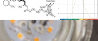
The supply voltage for single-color LEDs is 2..2.4 V (red, yellow, yellow-green, orange) or 3.0...3.6 V (white, cyan, green, magenta, pink). These two ranges are for LEDs of different colors; they have slightly different physical principles of operation. Accordingly, the brightness of the glow is very different.
Here is a reference table for voltages and other parameters of LEDs, taken from the seller’s website:
Table of LED parameters for chandeliers (and not only!) of different colors.
Forward current (If) of all models is 20 mA . This current is optimal in terms of the brightness/durability ratio. That is, the lower the current, the longer the LED will work. And the more current, the brighter.
I discussed this aspect in detail, in particular, in an article about installing an LED strip in a suspended ceiling.
Multi-color (multi-color) can be divided into two types, according to the method of switching colors:
- LEDs without control, with automatic color switching. Switching can be fast or slow, two or three colors.
- LEDs with control, when to turn on one color or another (2 or 3), you need to apply voltage to the desired output of the LED. Voltages, depending on the color, can be different - 2 or 3 Volts.
There are LEDs with a voltage of 5V. This mainly applies to two-color models. Then, the following driver is used:
RB Synchronous double controller – driver for serial LEDs 5 V
This driver says “RB Synchronous double controller” . The number of LEDs is 31-40 pcs, the voltage on each is 5 V. The inscriptions and parameters of such drivers will be discussed in more detail below.
To be honest, I haven’t quite figured out how to use such a driver. I assume that it is the same as the one discussed in the article, only the difference is in the forward voltage, which is not 3V, but 5V. Who can confirm or deny this - please write about your experience in the comments.
There is little specific information on the types of LEDs on the Internet, and it is difficult to use - after all, LEDs are transparent and do not have inscriptions. All that remains is to focus on the sellers’ descriptions (links will be at the end of the article). Or find out experimentally. Below, in the part about repairs, we will tell you how.
The chandeliers use LEDs with a transparent round body, diameter 5 (4.8) mm. Another feature is LEDs in chandeliers without a lens, with a shortened body, like a “straw hat”. They have a wide radiation pattern.
LEDs have wire leads for soldering. Although, in chandeliers they are never soldered, but inserted directly into the “mother” connector. The main thing is to maintain polarity.
LED light bulbs in chandeliers
99% of LED bulbs are 12 V AC or DC. Most often now you come across light bulbs with universal power supply, 12 VDC/VAC, which are powered by a 12 VAC electronic transformer. Such transformers (more precisely, voltage sources, or drivers) are much cheaper than those for direct current.
In this regard, it is possible to change halogen bulbs to LED bulbs without any modification at all. If the chandelier uses a transformer with an output voltage of 12 VAC.
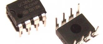
LED light bulbs, as a rule, have a G4 connector (more precisely, a base), which was used in halogen lamps.
Why is “applied” in the past tense? Because halogens are now dying out.
Such a light bulb is shown in the photo above. If anyone doesn’t understand, the transparent little belly is on the left)
Parallel or serial connection?
In the comments, my readers often have a question: are the LEDs in the chandelier turned on in parallel or in series? Often, in order to answer this fundamental question, you need to find out what we are talking about - LEDs or LED light bulbs?
We can confidently say that the LED bulbs are switched on in parallel and are powered by a driver (voltage source) of a stable voltage of 12V. The same applies to halogen and any lamps. Not only in chandeliers, but always and everywhere.
Another thing is LED matrices, which are not used in chandeliers, but are mainly used in spotlights. The main thing for power supply there is a stable current.
My articles on the topic. Installation and repair of LED spotlights.
And something in between - a driver that turns alternating voltage into constant, without any stabilization of voltage and current. LEDs are connected in series to the output of such a driver; it is only important that the number of LEDs be within certain limits. These are exactly the ones used in chandeliers for sequential switching.
If you have come across a chandelier where LEDs were connected in parallel, share your experience in the comments. These are probably some special LEDs.
Okay, enough theory, now the fun part -
Typical frequently asked questions from readers
Why, after turning off the LED chandelier with the control panel, does it turn off, but a residual glow remains?
Yes, despite their efficiency, LED lamps often suffer from a dim glow after they are turned off. As a rule, among the most likely reasons for this phenomenon are: 1) The presence of backlight on the switch - if there is an LED or lamp indicating the location of the switch in the dark, they bypass the circuit of contacts. For classic incandescent lamps, this backlight does not create lighting effects. But for LED models, the shunt circuit produces a sufficient level of electrical signal that allows the bulb to dimly glow. To fix this, you need a switch without backlighting, or you can cut the power cord in the existing one. 2) Low quality LED lamp - when using cheap models, manufacturers often skimp on current stabilizers. Which can cause a number of problems in the future, including weak flickering or glowing when the switch is off. This is especially true in situations where the switch breaks the neutral conductor instead of the phase conductor. To eliminate it, you need to replace the lamp with a better model or connect the phase conductor to the switch key. 3) Faulty wiring – causes the presence of leakage current in the power circuit of the LED chandelier. As a result, a weak glow of the lamps occurs due to the influence of low currents. During normal operation, the defect does not appear, but in the off state it is expressed in a weak glow or flickering of LED lamps. In some situations, diagnosing the location of damage to the wiring insulation is extremely problematic, but eliminating this malfunction requires eliminating the point of weakening of the insulation.
The LEDs in the chandelier stopped lighting
Let's look at it first
Design of a chandelier in which the LEDs do not light up
The chandelier is like this:
LED chandelier. LEDs connected in series do not work
If this is your first time seeing a chandelier from the back, I highly recommend my article on the construction of such chandeliers.
In this case, we have the simplest device: a chandelier for 2 groups, the 1st group - for 220V (4 E14 bulbs), the second group - 21 blue LEDs. The LEDs are connected in series through a driver, the device and circuit of which will be given below.
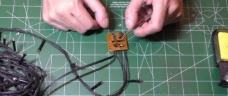
The controller that controls the chandelier using signals from the remote control is as follows:
Controller for a chandelier in which the LEDs do not work.
Not only is the controller Noname, but the label on the diagram is a complete mess; the conclusions should be like this:
- red – power phase,
- black – zero power,
- black – zero load (both wires are equivalent),
- white – phase output to load 1,
- yellow – phase output to load 2.
Well, to be completely grumpy, the third letter in the word “sacing” is wrong.
If the LED backlight on the chandelier stops working, then first of all you need to make sure that the controller supplies 220V power to the LED driver. Such controllers are easy to repair; read my article about Repairing LED chandelier controllers. There is also an exchange of experience among colleagues.
LED Serial Driver
On the body of this simplest device is the proud inscription LEDDRIVER.
Power supply for series-connected LEDs
In general, the Chinese call any power converters drivers, so there is no need to delude yourself.
Let's take a closer look at what is written on it:
Power supply for LEDs in a chandelier
Let's look at each power supply parameter:
- MHEN is a trademark. Identical devices are produced under the brands Jindel, ALED, Junyi, Jing Yi, and under other unpronounceable names.
- LED DRIVER – diode driver, as translated by an automatic translator. It may say LED Controller.
- 21-30 pcs – the number of LEDs that can be connected in series to this device.
- Model : GEL-11101A – model, it is also indicated on the board.
- Input : AC220-240 V 50 Hz. Everything should be clear here.
- Current : DC 60mA Max. This is the maximum current, which is not stabilized in any way; it is stabilized by the LEDs connected to the output. I wrote more about how this happens in the article about the Design and Connection of LED Strips.
- Output : Establish DC 3.0-3.2V. In fact, this is the voltage on one LED when the number within the specified limits is turned on (21-30 pcs.).
- LED 30 pcs Max – maximum number of LEDs.
- Ta, Tc – temperature of the environment and the device body.
- Jindel Electric is a Chinese manufacturer specializing in simple, cheap consumer electronics.
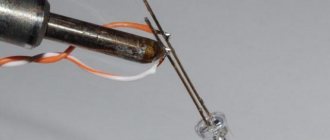
Checking the LEDs
A 3V LED is not an ordinary diode. A regular diode can be tested in the forward direction with a multimeter set to the “semiconductor testing” mode, and the readings will be about 800 Ohms. When the LEDs are tested in the forward direction, the LED lights up, albeit dimly. Otherwise, it doesn't light up. The multimeter does not show anything. More precisely, it shows infinity, i.e. "1".
In fact, when testing, a multimeter produces a voltage source of about 2V, and this is quite enough for a working LED to show signs of life.
To make everything completely clear, here's a picture:
Design, dimensions and pinout of an LED for a chandelier.
The anode to which the “plus” power is supplied is longer than the cathode to which the “minus” is supplied. The LED on the left shows a schematic diagram of a diode to make it clearer.
We apply the “plus” of the multimeter to the anode, and “minus” to the cathode. Thus, you can easily find out the polarity of the LED, its serviceability, and color. And based on the color, use the table above to find out the operating voltage.
In the chandelier that I was repairing, I started ringing the diodes, and realized that they would all have to be changed. Some showed 2-3 ohms in both directions, some showed 1000 ohms, some showed infinity. The result of inept repairs. Even if 1 or 2 LEDs are out of order, you should think about replacing everything, because... their parameters have inevitably changed (yes, we are all aging), and the new ones will have different parameters.
As a last resort, 1 or 2 LEDs can be replaced with jumpers or a resistor, the resistance of which will be calculated below. The jumper can only be installed if the remaining number of LEDs is not less than what is indicated on the driver. Otherwise, the “lucky ones” will not burn for long, but brightly.
Elena will also tell us how to check the LEDs in a chandelier:
Checking the Serial LED Power Driver
In general, all LEDs need to be changed. What about the driver?
To make sure the driver + LED tandem works, I assembled (soldered) the following bright design:
Checking the driver and LEDs before installing on the chandelier
As you can see, I use Vago terminals everywhere. Convenient and practical.
So, the measurement data is like this.
The output voltage of the driver (its device and its circuit will be for dessert) at idle (no load) is 305 V DC.
We connect a load of 22 LEDs (see photo above). We get - the voltage at the driver output is 80 V , the voltage on each LED is 80 / 22 = 3.63 V. According to measurements on each diode, this was approximately the case. As you can see, the voltage is slightly higher than the nominal value (3.0...3.4V), because the chandelier should shine brightly!
OK.
Now we connect 30 LEDs in series.
LEDs before installation in a chandelier. Connection for testing
Let's send current through the wires:
Checking 30 LEDs before installing in a chandelier
Measurement results. The driver output voltage is 107 VDC , one driver is 3.54 VDC .
That is, in principle, such a driver can power 40 diodes without a noticeable decrease in brightness.
That's it, the next day I installed these diodes with a driver in the chandelier, the owner was happy, and so was I.
How to prevent lamps from burning out?
It is impossible to protect yourself from all possible breakdowns, but many can be prevented. To prevent the connection of wires from causing the lamps to burn out, you should use copper wiring with a solid-core cable of the VVG type. The ends of the twisted wire must be soldered or crimped with special lugs. And if you have access to the distribution box, then you need to solder all the connections in it. Another way to connect wires is with a terminal block.
When replacing a switch, it is advisable to install a dimmer. This will prevent the possibility of failure of the lamp at the moment of switching on, since the device protects against voltage surges, short circuits and overheating.
If the contacts become oxidized, the cartridge can be cleaned of deposits. However, there is a high probability of a repeat breakdown in the near future. Therefore, it is recommended to replace the socket with a new one or purchase another chandelier if repairs cannot be made for some reason.
To protect your home from high voltage, you can purchase a voltage stabilizer or relay. This equipment is expensive, so not everyone can afford it. An alternative would be to change lamps to LED or fluorescent ones . This will not only reduce the likelihood of burnout, but will also reduce energy costs and increase the illumination of the room several times.
Voltage surges can be neutralized by special devices. Electronic protection units, which are installed one on each switch, can protect against small surges. They allow smooth starting and are suitable for incandescent and energy-saving lamps.
Source and LED resistance calculations
Thanks to our circuit design teacher, Elena Mikhailovna Shibaeva.
Now, for fun, let’s calculate the output resistance of the power supply and the resistance of the LEDs. The calculations involve the good old Ohm with his famous law and the voltage divider formula.
So, for the case of 30 LEDs we have:
- Open circuit voltage of the current source – 305 V,
- Current source voltage under load – 107 V,
- The current in the circuit (yes, old Kirchhoff with his 1st law!) is 0.02 A.
We know the current from the declared parameters of the diodes, but we cannot rely on this figure for sure. Judging by the voltage on one diode, the current is much more!
To make the calculations clearer, I am attaching a diagram:
Circuit for measuring resistance
We assume that the input of the circuit is supplied with voltage from an ideal EMF source with zero internal resistance. A real source of electricity has an internal resistance Ri, which we will now calculate.
When measuring the open circuit voltage Un = Uхх = 305 V, since the input resistance of the voltmeter is much greater than the internal resistance of the source Ri.
When a load is connected, Un = 107 V, which means that the voltage dropping across the internal resistance of the source Ri is 305 – 107 = 198 V.
Knowing the current, let's calculate the internal resistance:
Ri = 198 V / 0.02 A = 9900 Ohm.
Is it a lot or a little? Everything is relative. In this case - in comparison with the load resistance:
Rн = 107 V / 0.02 A = 5350 Ohm.
This is the resistance of LEDs connected in series when a current of 0.02 A flows through them. This means that the resistance of one LED is 5350 Ohms / 30 = 178 Ohms.
This means that without changing the circuit parameters, one LED can be replaced with a 180 Ohm resistor. This coincides with the value obtained experimentally on one LED: 3.54 / 0.02 = 177 Ohms.
We see that the resistance of the power supply is greater than the load resistance. This means that in front of us is a current source. That is, when the load resistance (the number of LEDs) changes within certain limits, the current remains almost unchanged.
You can calculate the resistance of diodes, when there are 22 of them, it will be less due to the fact that the current will be greater, and the current-voltage characteristic of the diode is nonlinear.
Tricky question. Why, if the calculated resistance of the LED is 178 Ohms, does the tester in continuity mode (Ohmmeter) not show any resistance? Write your answer in the comments, I will be glad to know and savvy readers!
Okay, we've deviated somewhat from the topic.
Now - the promised dessert.
Main conclusions
Remote control of lighting is vital in public places with a large area (theatres, stadiums, concert halls). Similar systems are also purchased for residential premises.
The connection is not complicated, but requires compliance with some nuances. It is necessary to determine the operating range, select light bulbs and the location of the lamp, and take into account the characteristics of specific conditions. Remote control is suitable if you need to expand the functionality of a double or triple switch.
The best option is to purchase a lighting fixture equipped with a remote control system. This makes the connection easier, since there is a ready-made circuit. You can do this kind of work yourself if you first get advice from a qualified specialist.
Remote system breakdowns do happen, but fixing them rarely creates problems. In the worst case scenario, a new kit is purchased and installed.
Device and circuit of the LED chandelier driver.
Driver circuits for LED lamps are also in this article. There these are stabilized current sources.
LEDs just need current, that is, a source with a high output resistance. If the LED is connected to a voltage source (whose output resistance is much lower than the resistance of the diode), then the current after a certain voltage will increase very quickly until the diode burns out.
This is how I burned a diode during laboratory work in physics in the 2nd year)
Power supply (inverter) for sequential switching of chandelier LEDs
And this driver is the simplest device, I soldered these in the 7th grade, in a radio club. It is a stretch to call it a current source, due to the fact that its output resistance is greater than or equal to the load resistance. We calculated this above.
We open it up and see a simple board without a single active element:
Let's disassemble the LED driver
Brown barrels are ballast (limiting) capacitors. They are for an operating voltage of 400 V, a capacitance of 0.33 μF:
LED Driver Limiting Capacitor
and 0.82 µF:
LED Driver Limiting Capacitor
On the cases they say 334 and 824, respectively. What does this mean - look for “Alphabetical designations on capacitors”. I wrote about this in an article on repairing a chandelier controller with a remote control, link above.
View from the soldering side:
Driver for powering serial chandelier LEDs. Solder side diagram.
And finally,
The most common problems and how to solve them
Chandeliers equipped with a remote control system break down more often than with traditional shutdowns. The reasons can be different - from the need to replace batteries to the failure of the radio, power supply or software board.
The lamp does not turn on at all: neither from the remote control nor from the switch
If the chandelier stops turning on both from the switch and from the control panel, you need to check the presence of voltage in the network and the functionality of the battery (it is better to replace it immediately). If there is current and the battery is new, but the problem is not solved, use a multimeter to check the serviceability of the light bulbs.
The incandescent lamps are unscrewed and the filaments are examined. The absence of breaks does not indicate serviceability, so a check with a multimeter is necessary. One probe is fixed on the thread of the base, the second - on the end. If the tester does not respond, the light bulb has burned out.
Checking halogen lamps is carried out similarly (probes are applied to the terminals). If the product is working properly, the resistance is 0.5-1 Ohm. When checking diodes, a positive multimeter probe is applied to the anode, and a negative one to the cathode. The voltage drop value appears on the display. When changing the polarity, the voltage does not change if the bulb is intact.
Driver circuit for LEDs in a chandelier
The circuit is very simple, maybe it will be useful for someone in repairs:
Driver for powering serial chandelier LEDs. Electric scheme
Briefly the device. Ballast limit chain – C1, C2, R1. Most of the voltage drops on this circuit. Next, the alternating voltage is supplied to the diode bridge, and then to the filter R3, C3, R2.
If you need to slightly increase the voltage at the driver output under load (i.e., reduce its output resistance, see the part of the article with calculations), then you can increase the capacitance of the filter capacitor to 10...20 μF. Then the number of LEDs can be increased slightly.
And if you need to reduce the number of LEDs in a chandelier (for example, some have burned out), then you can reduce the ballast capacity by removing one of the capacitors C1, C2. It's experimental.
Video on the topic
Remote control (remote control) of a chandelier is more convenient than using a switch. But there is also a drawback - the ability to forget the location of the remote control (remote control). This doesn't happen with a wall switch. Therefore, when switching to radio remote control, you should not give it up.
There are several types of pendant lighting you can buy:
- with LEDs;
- with halogen lamps;
- with conventional incandescent light bulbs;
- combined.
LEDs can be in the form of individual elements or garlands, allowing you to create special effects. They are connected via a capacitor. To connect halogen light bulbs, transformers are required to convert the voltage.
The most complex combined models of lighting fixtures are more difficult to determine why they do not turn on.
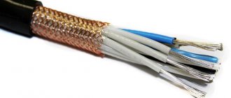
Testing the wire with a multimeter
It’s easy to test a wire that is wound into a coil and lies in front of a multimeter, but how can you test the wires with a multimeter when, for example, they are located in a wall under plaster? There is nothing wrong with this, you just need to create a closed circuit.
The easiest way to do this is with a short one. This is what electricians call the closing element. Any conductor, insulated or not, is suitable as a short for a socket.
Of course, if it is insulated, the insulation on both ends is removed at a distance of 1-2 cm.
| Attention! This operation can be performed only after turning off the input circuit breaker and checking that there is no voltage. To prevent accidental activation, a person must stand next to the machine so that no one turns it on. |
Then they determine which circuit needs to be tested and open the desired box. However, it is often more convenient to do the check on the machines themselves, on the contacts on the de-energized side. If the device shows a break, the measurement is made closer to the possible damage.
It is also possible to ring the lighting circuit, but this requires a little preparation. A plug machine can be easily screwed into a regular cartridge.
Before this, it is turned on and called to make sure that the circuit is closed. With other sockets and lamps, an individual approach is required.
What to do if the multimeter does not have a dialing mode
In this case, you can use the resistance mode. The result will be almost the same, only there will be no sound signal.