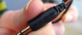
Today, LEDs are recognized by ordinary users, radio amateurs and industrial enterprises as the most environmentally friendly, compact and energy-efficient light sources. Low-power diodes are used to backlight monitors, mobile phones and in various toys, and high-power LEDs are used in workshop spotlights and festive luminescence of buildings, in the advertising business. But the unusual light source has a number of maintenance features, in contrast to energy-saving analogues (ESL) and incandescent lamps. It is not so easy, for example, to solder LEDs. This article is devoted to this issue.
Structure of diode elements
The main difference from other lamps is that LEDs have a positive and negative contact (anode and cathode). When soldering a diode in a circuit, it is important to take this into account.
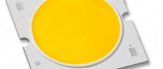
You also need to understand that there are DIP and SMD LEDs.
The positive contact in DIP is determined quite simply. It is worth taking a close look inside the flask. The positive terminal - the anode - is smaller than the negative one. In the picture, the plus is on the left.
There is a second way - look at the length of the leg. It is longer at the positive terminal.
The third way is with a multimeter. The black terminal of the device is negative, the red terminal is positive. Let's call:
The last method is suitable for both types.
This is perhaps the most important thing to know about the structure of an LED. If you are interested in the theory, we recommend watching the video:
Serial connection
Assembling a working circuit using one LED is not difficult. It's another matter when there are several of them. How to correctly connect 2, 3... N LEDs? To do this, you need to learn how to calculate more complex switching circuits. The series connection circuit is a chain of several LEDs, in which the cathode of the first LED is connected to the anode of the second, the cathode of the second to the anode of the third, and so on.
A current of the same magnitude flows through all elements of the circuit:
And the voltage drops are summed up:
Based on this, we can draw conclusions:
- It is advisable to combine only LEDs with the same operating current into a series circuit;
- if one LED fails, the circuit will open;
- The number of LEDs is limited by the power supply voltage.
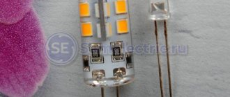
How to remove an LED from a strip
Another difficulty when soldering SMD type is replacing the old element with a new one in the LED strip. Solved in a simple way:
- Before unsoldering the diodes, secure the tape so as not to get the soldering iron on the conductive paths.
- Carefully melt the tin around the contacts and slide a blade under the diode. We lift it first on one side, then on the other, until the diode is free.
Connection Rules
Pieces of LED strip are connected, observing polarity. The product with single-color bulbs has 2 contacts. There are 4 contacts on the RGB strip. The wire is used with a cross-section of 0.75–0.8 mm in multi-colored insulation so as not to confuse the poles.
Splicing over 5 m is not recommended. Due to the voltage drop, the distant LEDs will not glow at full power.
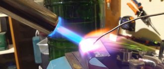
To solder wires, use a soldering iron with a power of 25–60 W. The maximum tip heating temperature is 300 °C. You will need flux, fine solder and rosin. Without a soldering iron, connections are made using connectors.
Soldering wires at an angle
When the LED backlight is made of several parallel strips, to pair them, it is better to solder the wires to each piece of strip at an angle of 90°.
Moreover, the minus and plus are fixed on the contacts of two adjacent diode blocks. This connection does not affect the glow of the diodes, but the wires are located without an overlay. For RGB strips, 4 wires are soldered at an angle.
Soldering silicone coated tape
A protective silicone coating hides the current-carrying contacts. To get to them, clean them with a sharp knife.
If you have to solder wires to a tape with IP68 protection, then after the entire procedure the exposed edge is pushed inside the protective shell. The void is filled with liquid silicone to a depth of 10 mm and a plug is installed by threading current-carrying conductors through the technical holes.
When are connectors needed?
To quickly connect the tape with wires or two pieces together without soldering, connectors are used. Connecting elements are selected of the appropriate width. The most common sizes are 8 and 10 mm. The number of contacts in the connector and on the LED strip must match.
Connectors are divided into three types:
- straight elements for splicing two pieces of tape;
- to connect two pieces at an angle of 90°;
- for connecting with wires to obtain an arbitrary angle.
According to the type of connection, connectors are:
- clamping;
- with latch;
- piercing.
The need for a connector arises when there is no soldering iron or for a temporary connection.
Disadvantages of connecting connectors
The connector is convenient for quick connection and does not require additional insulation. However, at the point of connection of current-carrying contacts, the cross-section decreases. During prolonged operation, heating occurs.
The contacts burn out, impairing current conductivity. The LEDs located next to the connector suffer from heating. Parts fail or the brightness of the light decreases.
Lack of soldering is accompanied by oxidation of contacts. Copper turns green when exposed to oxygen. The current flows weaker through the contacts. The diodes begin to dim, blink, and eventually stop lighting.
Overlapping connection without wires
To properly overlap two pieces, the ends of the LED strip are cut off close to the current-carrying contacts. The adhesive layer is peeled off the back side of one piece. The contacts are lubricated with flux and tinned with tin until a silver film appears.
Two pieces of tape are overlapped, observing polarity. The contacts are heated with a soldering iron for no more than 5 seconds. During this time, the tin will create a strong connection.
How to desolder an LED from an LED light bulb
Instead of incandescent light bulbs or energy-saving lamps, you cannot insert LEDs into the socket; you need a kind of intermediary. It is a lamp body in which several crystals are located on the board.
For convenience, it is recommended to tightly wrap copper wire around the tip, with a cross-section of no more than 4 mm.
Using tweezers or a needle, move the crystal down, parallel to the contacts.
Common mistakes
Inexperienced craftsmen often make the following mistakes:
- Poor soldering quality. This usually happens to beginners; as a result of soldering, poor contact is obtained and the lamp simply does not work.
- The soldering iron is heating up too much. At temperatures above 300 degrees, the current-carrying threads burn out.
- The use of aggressive fluxes that corrode contacts.
- Failure to observe polarity when installing LEDs on the board.
In order for the new element to work for a long time and not burn out, it is necessary to remove the remaining solder before soldering. It is advisable to use wire braid for this.
Errors made during soldering can cause an explosion or instant burnout of the lamp during the first turn on.
How to solder a resistor to an LED
If your circuit does not provide for current limitation by the so-called driver, then you can use resistors the old fashioned way.
It is impossible to connect LEDs directly to the network, since in addition to the increased current, it is also variable. The resistor and driver convert the current to direct current.
Each LED ideally needs a separate resistor. This is if there are few diodes. If there are, for example, a hundred of them, as in some garlands, or even a couple of dozen, you will have to purchase a driver.
If you are encountering the concepts of “resistor” and “driver” for the first time, we have selected visual instructions:
The resistor must be connected in the circuit after the power supply and before the LED. It just solders. In the chapter “Features of soldering” we left a video on how to solder any contact (see above). There are no special features here. The only thing that can be doubted is the choice of flux, that is, a substance that cleans the contact surface from oxide and/or grease film. As an option - a special paste.
220 V LED light bulb design
Repairing an LED light bulb yourself is only possible if you understand what parts it consists of and how it all works. This will allow you to look for faults yourself. The design of an LED light bulb is not too complicated. When viewed from the outside, three parts can be distinguished:
- plastic or glass light diffuser,
- metal, plastic or ceramic radiator for heat removal,
- base of one of the standards.
To repair an LED light bulb with your own hands, you will need to get to the insides - all the problems are concentrated here.
What parts does an LED lamp consist of?
If we disassemble the LED lamp, we will find an electrical part inside, where we will look for damage. This:
- Voltage converter/stabilizer or driver. It is located half in the base and half in the heat sink.
- Board with LEDs.
As you can see, it’s not too difficult, although there are a lot of variations. For example, in some models the driver is soldered on the same board where the LEDs are mounted. This is an “economy” solution and is usually found in cheap light bulbs. In others there is only one LED. These, on the contrary, are expensive models, since one large and powerful LED costs significantly more than a bunch of small ones with the same (or greater) glow power.
Selecting soldering paste
The quality of any flux is expressed in the fact that during soldering it does not burn out, it only barely evaporates, and the products of its decomposition are easily removed with a solvent. The best flux is special pastes. We chose the top names based on the experience of familiar masters:
- Interflux 2005 and 8300
- Kingbo RMA-218
- Amtech RMA-223
- Rexant BGA and SMD flux gel
Just in case, keep in mind the old, “old-fashioned” ways of finding flux in a remote village. This is an aspirin tablet, fruit juice, olive oil, ammonia with glycerin, rosin with alcohol. The most obvious one for rural areas is pine or spruce resin. You need to melt the resin over low heat and then pour it into matchboxes.
Required materials and tools
To solder SMD LEDs you will need:
- soldering iron with the necessary parameters;
- side cutters, tweezers, scissors;
- mounting needle or thin awl;
- solder and flux. Regular rosin or a special liquid composition, which is an alcohol solution, will do. An aspirin tablet is often used;
- thin brush for applying liquid flux;
- a magnifying glass on an adjustable stand (bracket), which is used by jewelers;
- soldering gun (component of a soldering station).
Wiring of planar parts
So, how does the process itself work? Read something here. We bite off small pieces of Rose or Wood solder (alloy). We apply our flux liberally to all contacts of the microcircuit. We put a drop of solder on Rose, on both sides of the microcircuit, where the contacts are located. We turn on the soldering iron and set it using a dimmer, the power is approximately 30-35 watts, I don’t recommend it anymore, there is a risk of overheating the microcircuit during dismantling. We pass the tip of a heated soldering iron along all the legs of the microcircuit, on both sides.
Dismantling using Rose alloy
In this case, the contacts of the microcircuit will close, but this is not scary, after we dismantle the microcircuit, we can easily remove excess solder from the contacts on the board and from the contacts on the microcircuit using the dismantling braid.
So, we took hold of our microcircuit with tweezers, along the edges, where the legs are missing. Typically, the length of the microcircuit, where we hold it with tweezers, allows us to simultaneously move the soldering iron tip between the tips of the tweezers, alternately on both sides of the microcircuit, where the contacts are located, and slightly pull it up with tweezers. Due to the fact that when melting Rose or Wood alloy, which have a very low melting point (about 100 degrees), relative to lead-free solder, and even ordinary POS-61, and moving with the solder on the contacts, it thereby reduces the overall melting temperature of the solder .
Dismantling microcircuits using braid
And thus the microcircuit is dismantled without dangerous overheating. On the board we have the remains of solder, Rose alloy and lead-free, in the form of sticky contacts. To bring the board back to normal, we take the dismantling braid; if the flux is liquid, you can even dip its tip into it, and place it on the solder “snot” that has formed on the board. Then we heat it from above, pressing it with the tip of a soldering iron, and run the braid along the contacts.
Read also: Kt8232a1 how to check with a multimeter
Soldering braided radio components
Thus, all the solder from the contacts is absorbed into the braiding, transferred to it, and the contacts on the board are completely cleared of solder. Then the same procedure must be done with all the contacts of the microcircuit, if we are going to solder the microcircuit into another board, or into the same one, for example, after flashing it using a programmer, if it is a Flash memory chip containing the BIOS firmware of a motherboard, or monitor, or what or other technology. This procedure must be performed to clean the microcircuit contacts from excess solder. After this, we apply the flux again, place the microcircuit on the board, position it so that the contacts on the board strictly correspond to the contacts of the microcircuit, and there is still some space left on the contacts on the board, along the edges of the legs. For what purpose are we leaving this place? So that you can lightly touch the contacts with a soldering iron tip and solder them to the board. Then we take a 25-watt EPSN soldering iron, or a similar low-power one, and touch the two legs of the microcircuit located diagonally.
Soldering SMD radio components with a soldering iron
As a result, the microcircuit turns out to be “stuck” and will not budge, since the melted solder on the contact pads will hold the microcircuit. Then we take solder with a diameter of 0.5 mm, with flux inside, bring it to each contact of the microcircuit, and simultaneously touch the tip of the soldering iron tip, the solder, and each contact of the microcircuit. I do not recommend using solder of a larger diameter; there is a risk of adding “snot”. Thus, we have solder “deposited” on each contact. We repeat this procedure with all contacts, and the microcircuit is soldered into place. If you have experience, all these procedures can actually be completed in 15-20 minutes, or even in less time. All we have to do is wash off the remaining flux from the board with solvent 646, or Flux Off cleaning agent, and the board is ready for tests after drying, and this happens very quickly, since the substances used for rinsing are very volatile. 646 solvent, in particular, is based on acetone. Inscriptions, silk-screen printing on the board, and solder mask are not washed off or dissolved.
The only thing is that dismantling a microcircuit in a Soic-16 or more multi-pin package in this way will be problematic due to difficulties with simultaneous heating and a large number of legs. Happy soldering everyone, and fewer overheated microcircuits! Especially for Radio circuits - AKV .
Basic methods of joining pieces of LED filament
The LED strip is connected in two ways: by soldering and using connectors. Which one to choose depends on the end goal. If you need a guaranteed reliable strong connection for years, it is better to use soldering. Connectors also work well to connect fragments, but this method is simpler and faster.
Now about the main pros and cons of each method of connecting LED filament fragments together. Information is presented in the form of tables.
Soldering method
| Behind | Against |
| The tape can have any desired turns and bends | If you have no experience or self-confidence, it is better not to take it |
| High connection strength | A very hot soldering iron is a big threat to the operation of the tape. |
| Contacts will not oxidize | |
| No need to deal with boards | |
| If you have a soldering iron, rosin, electrical tape, you don’t have to spend money | |
| The junction of the fragments is not noticeable |
Connection using connectors
| Behind | Against |
| Connectors are easy to install and remove | High humidity is the enemy of connectors |
| There are many types of connectors for different purposes | Contacts can quickly oxidize |
| The ability to give the LED strip any bends and shapes | If you purchase a connector of poor quality, the tape may simply not turn on. |
| No additional insulation required | The junction of the pieces will be noticeable |
| Connectors are affordable | |
| No super skills required for installation |
Installation of 220V power supply
If you have not completed electrical installation work, then you must first supply 220V voltage to the connection point of the tape. To do this, ditch the wall, or lay a cable channel and stretch a three-core cable VVGng-Ls 3*1.5 along it. Lead it directly to the distribution box where the power supply for the LED strip will be connected.
You can use the existing junction box where the main lighting is connected. The main thing is that the space allows you to freely connect additional wires and terminal blocks.
It is advisable to install the switch on the LED strip on the 220 Volt wires, and not in front of the strip on the outgoing 12-24V. In this case, the unit will not work continuously. Moreover, it is contraindicated for pulse units to operate without load. In addition, this will increase the level of security.
Pre-check and do not confuse phase, neutral and ground. Most often, the neutral is blue, the grounding conductor is yellow-green, and the phase conductor is of any other color. But you can’t trust color coding alone! More details on how to distinguish zero and phase without errors can be found in the article “How to determine phase and zero in electrical wiring.”
Next, you need to lay a cable from this junction box in a groove, corrugated sleeve or in a cable channel to the future location of the power supply. To place it, install a convenient shelf. It can be made from pieces of plywood or drywall. Place a dimmer nearby.
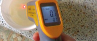
What is a multimeter
A multimeter is a device that can measure AC or DC current, voltage and resistance. It replaces three analog or digital instruments at once: ammeter, voltmeter and ohmmeter. It is also capable of changing the main indicators of any electrical network and ringing it. There are two types of multimeters: digital and analog. The first are portable devices with a display to display the results. Most multimeters on the market today are digital. The second type is already outdated and is no longer popular. It looks like a regular measuring instrument with a graduation scale and an analog needle showing the measurement value.
How are diodes connected?
Before you start soldering LEDs (for example, SMD type), you need to know how they are connected to the circuit or in series to each other (if we are talking about LED strips).
Note! LEDs are most often connected to a network with a voltage of 12 or 9 V. But usually the devices are designed for a current consumption level of 0.02 A (20 mA).
The ideal option for LEDs is to connect them through a current stabilizer. It should be remembered that such stabilizers will cost slightly more than single LEDs (for example, SMD type). This must be taken into account when independently assembling radioelectric devices.
In order to power yellow and red LEDs, a voltage of 2.0 V is often required. At the same time, to power blue, green and white LEDs - 3.0 V. The following example will help to understand this issue:
- a 12 V battery is available, as well as 0.02 A and 2.0 V LEDs;
- the simplest solution here would be to supply a voltage of 2.0 V to each diode;
- in this case, the extra 10 V will need to be extinguished using a resistor. It is also often called resistance;
- Using Ohm's law, we calculate the resistance value (R = U/I). As a result, we get R = 10.0/0.02 = 500 Ohm;
- Also, in order to protect the resistance from excess heat, it is necessary to calculate its power. The result will be P = 10.0 * 0.02 A = 0.2 W.
For greater reliability, it is necessary to take a resistance of slightly larger capacity. Note! As the resistance power increases, its overall dimensions will naturally increase. Knowing the above aspects, you will be able to connect the LEDs to the battery correctly using a resistor for this. The main thing here is to strictly observe the polarity of the parts used.
DIY repair
There are no specialized service centers for repairing LED lamps. In case of warranty, they are simply replaced with new products, and the old ones are disposed of. Although there are some breakdowns that are easy to fix with your own hands. Therefore, if a warranty replacement is refused, you should try to repair the 220 V LED lamp yourself. But before that, you need to figure out why the light bulbs burn out. The reasons may be:
Voltage surges in the 220V network. A high voltage at the input can cause a breakdown in the LED lamp driver and lead to burnout of the emitting crystals. To prevent this from happening, protective devices should be used at the electricity input, for example, protection relays. Incorrectly selected lamp. As a result, the LED lamp will not be provided with the necessary cooling, which will lead to its overheating and combustion.
Therefore, when installing a light bulb, you should always pay attention to the instructions for the lamp, which indicate its maximum permissible power. Low quality elements used in the manufacture of the lighting source
To avoid such a problem, it is necessary to purchase only products from reputable manufacturers that must have a certificate.
Disassembling the LED illuminator
It is impossible to repair the lamp without disassembling it. Although they differ in their shapes, their design is very similar to each other. So, in the lower base part, which is screwed into the cartridge, the device driver itself is located. Above it is a radiator plate on which the LEDs are placed. From above they are closed with a cap, which can be transparent or matte. Disassembling any type of lamp begins with removing the protective cap, and only after that the driver is removed.
The lamp structure includes the following parts:
- protective cap;
- base;
- radiator with a set of LEDs;
- power driver.
Normal manufacturers make the top cap out of plastic, which is then fastened into the base. But there is one caveat - a sealant is used to fix the top cover.
In order to separate the halves, you should prepare a sharp tool. This could be a knife or a point bent in an “L” shape. A tool is inserted under the dome of the lamp and the glue applied to it is removed using circular movements. Once the glue is removed, the dome is removed by lightly rocking and pulling upward.
As a result, access to the radiator with LEDs will open. This radiator is pryed up by the same sharp object and pushed towards itself. Two wires will come from it, going to the lamp driver. If their length is not enough to remove the electronics board and LED strip, then the wires are soldered off.
Trouble-shooting
The most common cause of failure is LED burnout. Its integrity can be easily checked using a multimeter by switching it to vertebrae mode. The red probe touches the anode (plus), and the black probe touches the cathode (minus). The operating LED should light up. If it does not light up or a black dot is visible on its body, it is faulty. It is impossible to repair it, so you should unsolder it and solder a worker in this place.
If the LEDs are OK, then the problem is in the driver. First of all, the presence of voltage is checked both at the input and output of the board. In their absence, a common problem is a broken solder joint or a faulty electrolyte located in the circuit after the diode bridge. It is also the cause of the “strobe” effect. Next, in the continuity mode, the diode bridge and fuses are checked. It will be impossible to check the generation of the microcircuit and the key transistor without an oscilloscope. All faulty parts are replaced with the same or their taxes. And then a test run is done.
Checking with a multimeter
To check the electrical resistor, proceed as follows:
- Take the radio element that needs to be checked;
- Turn on the multimeter and set it to measure resistance;
- Set the measurement scale and its boundaries;
- In any way, connect one multimeter probe to one of the sides of the resistor, and the second to the remaining side;
- Record the measurements on the screen or analog scale and finish testing.
If the value is zero or very different from the nominal value, then the element is faulty and must be disposed of, since changing the value can damage the entire circuit. If the value is normal, then the electrical resistor can be used to create electronic circuits. When checking the values without soldering the electrical resistor, the influence of the shunt circuits should be taken into account.
Thus, the question was addressed: how to check a resistor with a multimeter or tester. In fact, there is nothing complicated, since this radio element is one of the simplest and most common among all and has only two contact outputs without taking into account polarity. That is why anyone who has a multimeter, tester or ohmmeter can check it.
LEDs are one of the most popular electronic components, used in almost any circuit. The phrase “blinking LEDs” is often used to describe the first task when testing the viability of a circuit. In this article, we will learn how LEDs work, give a brief overview of their types, and also deal with practical issues such as determining polarity and calculating a resistor.