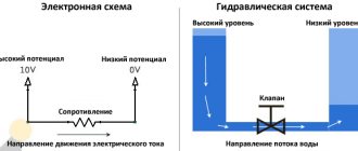
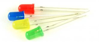
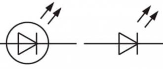
LEDs are used in almost all technology around us. True, sometimes it becomes necessary to adjust their brightness (for example, in flashlights or monitors). The easiest way out in this situation seems to be to change the amount of current passed through the LED. But that's not true. The LED is a fairly sensitive component. Constantly changing the amount of current can significantly shorten its life, or even break it. It is also necessary to take into account that you cannot use a limiting resistor, since excess energy will accumulate in it. This is unacceptable when using batteries. Another problem with this approach is that the color of the light will change.
PWM regulation
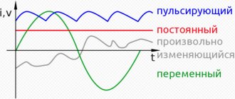
A way out of this situation may be to use pulse width modulation (PWM). With this system, the LEDs receive the required current, and the brightness is adjusted using high-frequency power supply. That is, the frequency of the feeding period changes the brightness of the LEDs. The undoubted advantage of the PWM system is maintaining the productivity of the LED. The efficiency will be about 90%.
Devices for controlling the brightness of LED strips
List of main devices used to control the brightness of the LED strip:
- Voltage stabilizers and linear regulators (have low efficiency, are considered obsolete and have limited use).
- Dimmers are compact pulse converters.
- Drivers are switching power supplies.
- RGB amplifiers are devices that increase the power of RGB LEDs.
- RGB controllers are devices for controlling multi-color ribbons.
- DMX controllers are complex professional devices designed specifically for spectacular light shows. Modern models are controlled from a computer using special software or have the form of remote controls with numerous buttons and knobs.
The simplest dimmer works based on variable resistors (rheostats). This method of adjusting lighting is considered ineffective and has low efficiency due to overheating and the need for cooling. Nowadays, manufacturers no longer mass-produce such devices; most often, radio amateurs make them themselves.
The regulator, which is based on the operation of an autotransformer, produces an almost ideal sinusoidal curve at the output. But such a device is large in size and weight, and adjustment will require considerable effort.
- Modular. They are installed in the electrical panel. The connection diagram for a dimmer of this design works with incandescent and halogen lamps through step-down transformers. To make them more convenient to use, the dimmer has an external button or a key switch. As a rule, a modular type of dimmer is used to regulate the brightness of lamps at the entrance gate, flights of stairs or yard lighting.
- On a cord. You can call it a mini-device that regulates the lighting of lamps that are not directly connected to the general electrical network, but are connected through a socket and plug (table lamps, sconces, floor lamps). This regulator only works with incandescent lamps.
- Monoblock. Externally, it is very similar to a regular switch. Works with different types of lamps; as a rule, this is indicated on the housing. The device is installed in the electrical circuit for a phase break; this dimmer is mounted instead of a switch.
Monoblock options are often used in apartments. In private residential buildings, it is convenient to install modular devices when you need to control the light in the adjacent area.
It is worth noting that there are still walk-through models of dimmers; they work on the same principle as walk-through switches, that is, the light can be adjusted in two places.
Musical keyboard
A very simple musical instrument (keyboard) for playing music can be made using a 555 chip. You can build an unusual musical instrument in the photo above. Graphite is used as a keyboard and a sheet of paper with notes is represented as holes in the paper.
The same circuit, but with ordinary resistors and buttons.
Controlling LED strip brightness control devices
By the way, with the help of such circuits you can control not only the speed of a DC motor, but also simply an active load - an incandescent lamp or some kind of heating element.
Expert opinion
It-Technology, Electrical power and electronics specialist
Ask questions to the “Specialist for modernization of energy generation systems”
Introduction By the way, with the help of such circuits you can control not only the speed of a DC motor, but also simply an active load with an incandescent lamp or some kind of heating element. Ask, I'm in touch!
PWM generators
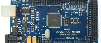
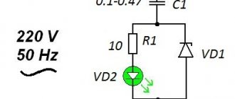
In a PWM system, a microcontroller or a circuit consisting of low-integration circuits can be used as a master oscillator. It is also possible to create a regulator from microcircuits that are designed for switching power supplies, or K561 logic chips, or NE565 integrated timer. Craftsmen even use an operational amplifier for these purposes. To do this, a generator is assembled on it, which can be adjusted. One of the most used circuits is based on the 555 timer. It is essentially a regular square wave generator. The frequency is regulated by capacitor C1. at the output the capacitor must have a high voltage (this is the same with the connection to the positive power supply). And it charges when there is a low voltage at the output. This moment gives rise to pulses of different widths. Another popular circuit is PWM based on the UC3843 chip. in this case, the switching circuit has been changed towards simplification. In order to control the pulse width, a control voltage of positive polarity is used. In this case, the output produces the desired PWM pulse signal. The regulating voltage acts on the output as follows: as it decreases, the width increases.
Board and assembly parts of the brightness control
The single-sided printed circuit board has dimensions of 22x24 mm. As you can see from the picture, there is nothing superfluous on it that could raise questions.
Board in Sprint Layout 6.0 file: reguljator-jarkosti.lay6
After assembly, the PWM dimmer circuit does not require adjustment, and the printed circuit board is easy to make with your own hands. The board, in addition to the tuning resistor, uses SMD elements.
- DA1 – IC NE555;
- VT1 – field effect transistor IRF7413;
- VD1,VD2 – 1N4007;
- R1 – 50 kOhm, trim;
- R2, R3 – 1 kOhm;
- C1 – 0.1 µF;
- C2 – 0.01 µF.
You can order a ready-made assembly from the author here.
Why PWM?
- The main advantage of this system is its ease. The usage patterns are very simple and easy to implement.
- The PWM control system provides a very wide range of brightness adjustment. If we talk about monitors, it is possible to use CCFL backlight, but in this case the brightness can only be reduced by half, since CCFL backlight is very demanding on the amount of current and voltage.
- Using PWM, you can keep the current at a constant level, which means the LEDs will not be damaged and the color temperature will not change.
Introduction
The exponential growth of LED lighting is accompanied by an expanding selection of chips for driving LEDs. Switching LED drivers have long replaced linear current sources, which consume significantly more energy. All applications, from flashlights to stadium scoreboards, require precise control of regulated current. In many cases, it is necessary to change the output intensity of LEDs in real time. This function is commonly referred to as LED dimming. This article introduces the basic concepts of LED theory as well as some brightness control techniques for switching LED drivers.
Would you like to meet NCP1014 in person? - No problem!
For those who, before starting to develop their own IP based on NCP1014, want to make sure that this is a truly simple, reliable and effective solution, ONSemiconductor produces several types of evaluation boards (see Table 1, Fig. 6; available for order through COMPEL) .
Table 1. Overview of evaluation boards
| Order code | Name | Short description |
| NCP1014LEDGTGEVB | 8W LED driver with 0.8 power factor | The board is designed to demonstrate the possibility of building an LED driver with a power factor > 0.7 (Energy Star standard) without the use of an additional PFC chip. The 8 W output power makes this solution ideal for powering structures like the Cree XLAMP MC-E, which contain four LEDs in series in one package. |
| NCP1014STBUCGEVB | Non-inverting buck converter | The board is proof of the statement that the NCP1014 controller is sufficient to build low-price power supplies for harsh operating conditions. |
Rice. 6. Appearance of the evaluation board
In addition, there are several more examples of ready-made designs of various IPs, in addition to those discussed in the article. This is a 5 W AC/DC adapter for cell phones [6], and another IP option for LED [7], as well as a large number of articles on the use of the NCP1014 controller, which you can find on the official website of the ONSemiconductor company - https:/ /www.onsemi.com/.
The COMPEL company is the official distributor of ONSemiconductor and therefore on our website https://catalog.compel.ru/ you can always find information about the availability and cost of chips produced by ONS, as well as order prototypes, including NCP1014.
LM3409 provides multiple brightness adjustment functions
National Semiconductor's LM3409 is a unique LED driver that provides the necessary functionality for simple analog and PWM dimming. This device provides four possible ways to implement LED brightness adjustment:
- Analog adjustment using direct control of the IADJ pin from a voltage source in the range 0...1.24 V.
- Analog adjustment using a potentiometer connected between the IADJ pin and ground.
- PWM control using the resolution pin.
- PWM control using external shunt FETs.
The LM3409 circuitry for analog adjustment using a potentiometer is shown in Figure 6. An internal 5-µA current source creates a voltage drop across the RADJ, which in turn allows the internal current sensitivity threshold to be varied. For the same purpose, the IADJ pin can be directly driven from a constant voltage source.
Rice. 6. Connection diagram of LM3409 for analog brightness control.
Figure 7 shows a graph of the LED current versus the resistance of the potentiometer connected between the IADJ and GND pins. The flat part of the curve at a current value of 1 A corresponds to the maximum rated current of the LED, which is set by the current control resistor RSNS, shown in Figure 4.
Rice. 7. LED Current vs. Potentiometer Resistance
Figure 8 shows the LED current as a function of the voltage at the IADJ pin. Note that this graph shows the same maximum LED current set by the RSNS resistor.
Rice. 8. LED current versus voltage at the IADJ pin.
Both analogue control options are easy to implement and provide very linear levels of LED brightness reduction up to 10% of the maximum value.