The following resistor connections are used: parallel, series and mixed.
Series connection of resistors
- this is the relative arrangement of the components in which the current moves in one direction and has a common value for each resistor. With such a connection, the voltage at each section will be proportional to the resistance of a particular resistor in the circuit.
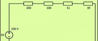
Schematic diagram of serial connection:
As you can see, there are three resistors connected in series in the circuit (there may be more). The resistance of the first resistor R1 = 20 Ohms. Second R2 = 70 Ohm. Third R3 = 10 Ohm.
As you can see, there are three resistors connected in series in the circuit (there may be more). The resistance of the first resistor R1 = 20 Ohms. Second R2 = 70 Ohm. Third R3 = 10 Ohm.
To calculate the total (equivalent) resistance in a series connection, you need to add up all the nominal resistances of the resistors included in the circuit:
For clarity, the presented diagram shows the voltages in each of the three sections. And the voltage drop occurs depending on the resistance of a particular resistor. The current in the circuit is common to all resistors ( I = I1 = I2 = I3
).
Therefore, according to Ohm’s law, the current strength at a known voltage of the power source (in this case U = 220 V) is determined by the formula:
Formulas for finding the voltage in a section of the circuit at a known current strength (in this case I = I1 = I2 = I3 = 2.2 A ):
Accordingly, U1 = 2.2 × 20 = 44 V; U2 = 2.2 × 70 = 154 V; U3 = 2.2 × 10 = 22 V. As a result, the sum of the potential differences across the resistors is equal to the total potential difference of the entire circuit (220 V).
What kind of lighting do you prefer?
Built-in Chandelier
The three resistors considered in a series circuit can be replaced with one with a resistance of 100 Ohms:
If you can replace several resistors with one, then a logical question arises why such a combination is used. In simple words, we can answer that sometimes it is impossible to select a resistor with the required parameters or it is necessary to create more complex electronic circuits. In this case, they resort to serial, parallel or mixed connection in the circuit.
Serial and parallel connection |
However, this method of electrical circuit layout also has serious disadvantages . The main one is the unreliability of a chain of series-connected conductors. If any of the connected devices fails, the entire circuit is switched off.
Expert opinion
It-Technology, Electrical power and electronics specialist
Ask questions to the “Specialist for modernization of energy generation systems”
Serial and parallel connection of resistances The operating parameters of the connected equipment largely depend on the chosen method of connecting sources and consumers. Ask, I'm in touch!
Parallel connection of resistors
Parallel connection of resistors
- this is such a mutual connection of components in which both terminals of one resistor are connected to the corresponding terminals of another resistor or resistors.
1 / R = 1 / R1 + 1 / R2 + 1 / R3 + . + 1/Rn
. The reciprocal value of the total resistance of the circuit is equal to the sum of the reciprocal values of the resistances of parallel-connected conductors.
Let's calculate the total resistance for the above example with parallel connection of resistors:
For clarity, let’s simulate in the Electronics Workbench program the replacement of three parallel-connected resistors with one (R = 6.097 Ohms): As you can see, the calculation was made correctly, since the current in the circuit with a resistor of 6.097 Ohms is equal to the current in the circuit with a parallel connection (36.08 A ≈ 36.14 A).
For clarity, let’s simulate in the Electronics Workbench program the replacement of three parallel-connected resistors with one (R = 6.097 Ohms): As you can see, the calculation was made correctly, since the current in the circuit with a resistor of 6.097 Ohms is equal to the current in the circuit with a parallel connection (36.08 A ≈ 36.14 A).
Let us highlight the main features of parallel connection of resistors:
- The total resistance is always less than the resistance of any resistor connected in parallel.
- Increasing the number of resistors connected in parallel leads to a decrease in the total resistance and an increase in the total current in the circuit.
- If two resistors with the same resistance are connected in parallel, then the total resistance of these resistors will be exactly two times less than the resistance of each of the resistors included in this chain.
- If resistors of the same value are used in the circuit, then the formula for the total resistance is simplified and takes the form R = R1 / N
(R1 is the nominal resistance of the resistor; N is the number of resistors with the same nominal resistance).
Examples of calculations
As practical examples, we can consider several options for calculating circuit parameters in different connection schemes.
For resistors
The simplest example of a calculation would be a chain of two resistances - 10 Ohms and 100 Ohms, connected in a chain. 12 volts are applied to the circuit.
A series circuit of two resistors.
First you need to find Rtotal, it is equal to the sum of R1 and R2. Rtot=100+10=110 Ohm. Hence the current in the circuit is I=U/R=12/110=0.109 amperes. The drop on each element can be calculated based on the equalities U1=I*R1 and U2=I*R2. Hence U1=1.1 V, and U2=10.9 V. Obviously, U1/U2=R1/R2. The first element will dissipate power P1=U1*I=1.1*0.109=0.12 watts (for practice, a standard component of 0.125 watts is suitable), and the second one will dissipate P2=U2*I=10.9*0.109=1 .19 watts (for practical implementation you will need a two-watt power supply).
If you connect these same two resistors in parallel and apply the same voltage, the parameters will be distributed differently.
Connecting elements in parallel.
First you need to determine Rtot=R1*R2/(R1+R2)=110*10/(110+10)=1100/120=9.17 Ohm (less than the smallest value of 10 Ohm). The total current will be I=U/Rtotal=12/9.17=1.31 amperes. Through the first element I1=U/R1=12/10=1.2 amperes will flow, through the second I2=U/R2=12/100=0.12. Obviously, I1+I2=I (taking into account rounding errors). The power required is:
- P1=I1*U=1.2*12=14.2 watts;
- P2=I2*U=0.12*12=1.42 watts.
If there is a mixed connection of elements, you must first convert the circuit to the same type - parallel or serial. Let there be a diagram of the following type.
Conversion of a mixed circuit.
In this case, it is convenient to replace the parallel assembly of R1 and R2 with a resistor with an equivalent resistance of R12, and R3 and R4 with R34. First, R12=R1*R2/(R1+R2)=9.17 Ohm is found. Using the same method, R34=150*5/(150+5)=4.8 Ohm is calculated. Then the total resistance of the equivalent circuit will be equal to R12+R34=9.17+4.8=13.97 Ohms.
Hence I=U/R=12/13.97=0.86 amperes. On the “garland” R1R2 the drop is U12=I*R12=0.86*9.17=7.87 volts, and on R3R4 the drop will be U34=I*R34=0.86*4.8=4.13 volts. Next, we need to return to the original circuit and consider separately the section of the R1R2 circuit with the found parameters.
Section of the circuit containing R1 and R2.
Hence I1=U/R1=7.87/10=0.787 amperes, I2=U/R2=7.87/100=0.0787 amperes. By power – P1=U*I1=7.87*0.787=6.2 watts, P2= U*I2=7.87*0.0787=0.62 watts.
The section containing the R3R4 elements is calculated in the same way.
Basic laws
- with a series connection, a current of equal strength flows through each section of the circuit;
- the total resistance of the circuit when connected in series is equal to the sum of the resistance of all conductors;
- The voltage in the electrical network when connected in parallel is the same for each section;
In accordance with Kirchhoff's first law, the algebraic sum of the currents in a node is always equal to zero. Thanks to this, it is possible to obtain a formula for finding the equivalent circuit resistance if the resistance of each load is known. It has the following form: Ro =R1*R2 / R1+R2.
For series connection of loads, we apply Kirchhoff's second law. According to it, the sum of the EMF in a closed electrical circuit is equal to the sum of the voltage drops at each load. As a result, the total resistance can be determined using the following formula: Ro = R1 + R2.
You can also calculate the inductance for various types of coil connections. In the case of sequential, everything is quite simple, just use the following formula: Lo = L1 + L2. In fact, instead of two elements, you can install one with the corresponding inductance value.
When connecting coils in parallel, the situation becomes more complicated, since three options are possible:
- the magnetic fields of the coils do not intersect: Lo = L1 * L2 / L1 + L2;
- the coils are connected in the same direction and their fields intersect: Lo = L1 * L2-M 2 / L1 + L2 - 2 M;
- the intersection of the fields is observed with counter-connection: Lo = L1 * L2-M 2 / L1 + L2 + 2 M.
Today, you can often use an online calculator to calculate these and other indicators, for example, capacitor capacity.
Expert opinion
It-Technology, Electrical power and electronics specialist
Ask questions to the “Specialist for modernization of energy generation systems”
Series and parallel connection of conductors ℹ️ formulas Let us recall that the positive terminal of the source is indicated by a longer line, so that the current in this circuit flows clockwise. Ask, I'm in touch!
Types of electrical wiring
Information about electrical circuit connections is closely intertwined with the topic of wiring and complements the methodology of electrical installation work. There are several types of wiring. However, before moving on to them, it is worth considering how wiring is formed in a private house:
- The power cable enters the building's distribution panel.
- The panel contains groups of automatic protection devices.
- Using automation and distribution buses, the cable is further divided into zones (consumer groups).
- The zones are divided into two groups: one is for sockets, the other is for lighting.
- The power cables of a separate zone enter the room, where they use their own wiring options. Thus, the power cable line going to the outlet can be connected to other outlets in a given room using the “loop” method, and the lighting line can be disconnected through a distribution box.
Types of electrical wiring connections:
| The star connection type (other names are boxless, or European) schematically looks like this: one socket - one cable line to the panel. That is, each socket and lighting point has a separate cable line, which goes directly into the panel and connects to a separate circuit breaker. The advantage of this technique is safety and the ability to control every electrical point. Also, with such wiring there is no need to install distribution boxes. The disadvantage of boxless connection is the increased wire consumption and, accordingly, increased labor costs for installing the system. |
| The “loop” is more economical compared to the “star”. You can depict a loop connection as follows: electrical panel or distribution box - socket - socket - socket. In other words, several electrical points are connected in series, and from them a common supply conductor goes either to the electrical panel or to the junction box. As you can see, this type of wiring connection is nothing more than a series connection in the context of an electrical circuit. |
| The most common type of wiring is using junction boxes. In this case, from the electrical panel, the power cable of a particular group branches out between consumers through distribution boxes, which are usually located above the switch near the entrance to the room. |
| Mixed wiring involves the simultaneous use of “star” and “loop” types in one system using distribution (junction) boxes. |
In their pure form, the listed types of disconnection are rarely used. As a rule, a mixed option is chosen. In this case, you must follow the rules for connecting the electrical circuit.
Parallel connection
Parallel is a connection of sections of a circuit in which the beginnings of the conductors are connected together at one point and the ends of all conductors are connected together at another point.
With a parallel connection, the voltage in each individual branch of the circuit will be equal to the total voltage in the circuit:
The current strength in an unbranched circuit will be equal to the sum of the currents of all individual branches.
When connecting conductors in parallel, the reciprocal of the total resistance of the circuit is equal to the sum of the reciprocals of the resistances of parallel-connected conductors.
With a parallel connection, the following relation is true:
those. The strength of currents in the branches of a parallel-connected circuit is inversely proportional to the resistance of the branches.
The advantage of a parallel connection is that if one of the elements fails, the rest of the circuit continues to function normally.
Expert opinion
It-Technology, Electrical power and electronics specialist
Ask questions to the “Specialist for modernization of energy generation systems”
Parallel and series connection of conductors in an electrical circuit. The circuit is also well suited in cases where it is necessary to form an electrical circuit of consumers with a low rated voltage. Ask, I'm in touch!
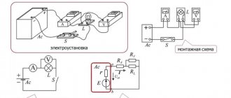
Electrical circuit and diagrams of possible types of electrical connections of its elements
The simplest electrical circuit can be defined as a set of elements (devices) and conductors, the purpose of which is the passage of electric current. The ES diagram in such a circuit is shown in the figure.
In general, the following elements are present in any electrical circuit:
- source of current (electricity) - battery, generator, etc.;
- consumers of electricity (its receivers) - various household appliances, electric motors, machine tools, heaters, etc.;
- electrical conductors (power lines) - wires, cables, cords;
Since our website has already discussed electrical wires and cables, let us dwell in a little more detail on connectors for electrical wires.
2.1. Wire connectors
The elements with which the ES is installed are usually called wire connectors. We will not dive into the depths of this problem, but will focus on ordinary electrical wiring in a house or apartment. Anyone in the house who is “their own master” is familiar with the problem of connecting wires firsthand. You can connect wires using a wide variety of methods - from conventional twisting to using terminal blocks (terminal blocks). Let’s say right away that it doesn’t matter how the wires are connected. The main thing is the reliability of this connection!
Let us consider, however, which connection of wires - traditional (welding wires, soldering wires, crimping wires, crimping wires) or modern (using a variety of clamps) is more reliable and durable. At the same time, it is important to remember that the safety of living in your home depends on this.
2.1.1. Twisting is still popular
Despite the availability of modern, safe and aesthetic factory connectors on the market, electricians still continue to use this method of connecting wires.
Its main disadvantages are:
- the connection is neither detachable nor one-piece type, since the wire strands are also subject to wear;
- Without experience and practical skills, you cannot perform strong twisting.
But for experienced electricians, such a connection of wires turns out to be not only durable, but also quite aesthetic (although electrical tape will still spoil its appearance).
2.1.2. PPE caps
This is an abbreviation for connection insulating clamps. They have an outer plastic casing that:
- does not support combustion;
- can be used at voltages up to 600 V;
- has good insulating characteristics and at the same time serves as protection against mechanical damage.
The caps are made in the form of a cone with a steel crimp spring inside. The application is quite simple - a twist of wires is inserted into the cap, and the spring also compresses it. However, their successful use requires certain skills. And of course, to expose the ends of the wires, it is better to use not a knife, but a special insulation stripper.
It is also important to twist the wires correctly, especially if there are several of them. And having inserted the twist into the cap, its rotation should be performed exclusively clockwise, but in no case vice versa.
You also need to know about their labeling:
- Caps are marked in gray and blue, respectively, for 2 and 3 cores with a cross-section up to ;
- orange, yellow and red caps are intended for connecting 2, 4 and 8 wires with a cross section of up to 2.5, respectively.
2.1.3. Terminal blocks (terminal clamps)
Their main advantage is the ability to connect cores made of different metals (for example, copper and aluminum, which cannot be twisted!!!). In practice, terminal blocks made of polyethylene are most often used; they are simple in design and, importantly, not expensive.
They consist of a number of cells with sleeves (tubes made of brass) inside each. The cores of the connected wires are inserted from both sides into this sleeve and are clamped with two screws, respectively. It should be remembered that with the help of such terminal blocks you can only connect single-core (not multi-core!!!) wires. And second, terminal blocks require periodic inspection (especially with aluminum conductors - they should be tightened in a timely manner).
2.1.4. Scotch-lock
These one-time couplings are used when working with wires designed for low operating current - in telephony, in low-power LED lamps, etc. The connection is made by the so-called. mortise contact and, therefore, preliminary exposure of wire cores is not required.
In addition, such universal couplings:
- relatively cheap;
- do not require special tools for crimping (you can use ordinary pliers);
- do not allow moisture to pass through;
- easy to replace.
2.1.5. Sleeves
The use of these powerful clamps is advisable when it is necessary to connect several wires. This is, in fact, a tinned copper tube into which wires are inserted, after which the tube is crimped with special pliers (crimper).
Thus, you can connect the wires using a variety of clamps. Therefore, when choosing them, you should take into account the type and number of wires requiring connection, as well as the location of the future connection. But we repeat once again - the main thing is that it is reliable and safe!
Serial connection of energy receivers
Receivers of electrical energy can be connected to each other in three different ways: in series, in parallel or mixed (series - parallel). First, let's consider a sequential connection method, in which the end of one receiver is connected to the beginning of the second receiver, and the end of the second receiver is connected to the beginning of the third, and so on. The figure below shows the series connection of energy receivers with their connection to the energy source
An example of serial connection of energy receivers.
In this case, the circuit consists of three serial energy receivers with resistance R1, R2, R3 connected to an energy source with voltage U. An electric current of force I flows through the circuit, that is, the voltage at each resistance will be equal to the product of the current and resistance
Thus, the voltage drop across series-connected resistances is proportional to the values of these resistances.
From the above, the rule of equivalent series resistance follows, which states that series-connected resistances can be represented by an equivalent series resistance, the value of which is equal to the sum of series-connected resistances. This dependence is represented by the following relations
where R is the equivalent series resistance.
Ways to calculate electrical circuits
The calculation of electrical circuits branches into many methods used in practice, namely: the method of equivalent transformations, a technique based on Ohm's and Kirchhoff's postulates, the superposition method, the method of loop currents, the method of nodal potentials, the method of an identical generator.
The process of calculating an electrical circuit consists of several mandatory steps that allow all calculations to be made fairly quickly and accurately.
Before finding out or calculating the necessary parameters, the calculated electrical circuit is transferred schematically to paper, which contains symbolic designations of its constituent elements and the order of their connection.
All elements and devices are divided into three categories:
- Power supplies. The main feature of this element is the conversion of non-electric energy into electrical energy. These energy sources are called primary energy sources. Secondary energy sources are devices whose inputs and outputs contain electrical energy. These include rectifiers or voltage transformers;
- Devices that consume electrical energy. Such elements convert electrical energy into any other energy, be it light, sound, heat and the like;
- Auxiliary circuit elements, which include connection wires, switching equipment, protection and other similar elements.
Also, the basic concepts of an electrical circuit include:
- A branch of an electrical circuit is a section of a circuit with the same current. Such a branch may include one or more elements connected in series;
- An electrical circuit node is a connection point between three or more circuit branches;
- An electrical circuit circuit, which is any closed path passing through several branches.
Designation of branches, nodes and contours in the diagram
Mixed connection of energy receivers
The most widespread is a mixed connection of electrical energy receivers. This connection is a combination of series and parallel connected elements. There is no general formula for calculating this type of connection, so in each individual case it is necessary to highlight sections of the circuit where there is only one type of receiver connection - serial or parallel. Then, using the formulas of equivalent resistances, gradually simplify these fates and ultimately bring them to the simplest form with one resistance, while calculating currents and voltages according to Ohm’s law. The figure below shows an example of a mixed connection of energy receivers
An example of a mixed connection of energy receivers.
As an example, let's calculate currents and voltages in all sections of the circuit. First, let's determine the equivalent resistance of the circuit. Let us select two sections with parallel connection of energy receivers. These are R1||R2 and R3||R4||R5. Then their equivalent resistance will be of the form
As a result, we obtained a circuit of two serial R12R345 energy receivers with equivalent resistance and the current flowing through them will be
Then the voltage drop across sections will be
Then the currents flowing through each energy receiver will be