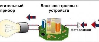
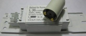
A starter for fluorescent lamps is included in the package of an electromagnetic ballast (EMP) and is designed to ignite a mercury lamp.
Each model released by a specific developer has different technical characteristics, but is used for lighting equipment powered exclusively by AC power, with a maximum frequency not exceeding 65 Hz.
We suggest you understand how a starter for fluorescent lamps works and what its role is in a lighting device. In addition, we will outline the features of different starting devices and tell you how to choose the right mechanism.
How does the device work?
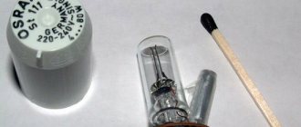
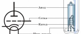
The optional starter (starter) is quite simple. The element is represented by a small gas-discharge lamp, capable of forming a glow discharge at low gas pressure and low current.
This small-sized glass cylinder is filled with an inert gas - a mixture of helium or neon. Movable and fixed metal electrodes are soldered into it.
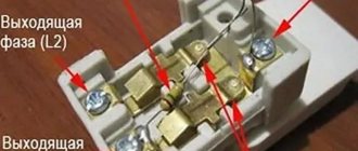
All light bulb electrode coils are equipped with two terminal blocks. One of the terminals of each contact is involved in the electromagnetic ballast circuit. The rest are connected to the cathodes of the starter.
The distance between the starter electrodes is not significant, so it can easily be broken through by the mains voltage. In this case, a current is generated and the elements included in the electrical circuit with a certain amount of resistance are heated. The starter is one of these elements.
The designs of starters for fluorescent lamps have an almost identical device: 1 – choke; 2 - glass flask; 3 – mercury vapor; 4 – terminals; 5 – electrodes; 6 — body; 7 – bimetallic contact; 8 – inert gas substance; 9 – tungsten filaments LDS; 10 – drop of mercury; 11 – arc discharge in the bulb (+)
The flask is placed inside a plastic or metal housing that acts as a protective casing. Some samples additionally have a special inspection hole on top of the lid.
The most popular material for block production is plastic. Constant exposure to high temperatures allows it to withstand a special impregnation composition - phosphor.
The devices are produced with a pair of legs that act as contacts. They are made from different types of metal.
Depending on the type of design, the electrodes can be symmetrical movable or asymmetrical with one movable element. Their leads pass through the lamp socket.
A capacitor with a capacity of 0.003-0.1 μF is connected parallel to the electrodes of the flask. This is an important element that reduces the level of radio interference and is also involved in the process of lighting the lamp.
An obligatory part in the device is a capacitor capable of smoothing out extra currents and at the same time opening the electrodes of the device, extinguishing the arc that occurs between the current-carrying elements.
Without this mechanism, there is a high probability of contact soldering when an arc occurs, which significantly reduces the life of the starter.
In everyday life, the most popular types of ballasts are those with a symmetrical contact system and a starting electrical circuit. Such samples are less affected by voltage drops in the electrical network
Correct operation of the starter is determined by the supply voltage. When the nominal values are reduced to 70-80%, the fluorescent lamp may not light up, because the electrodes will not be heated sufficiently.
In the process of selecting the required starter, taking into account the specific model of a fluorescent lamp (fluorescent or LL), it is necessary to additionally analyze the technical characteristics of each type, as well as decide on the manufacturer.
Device
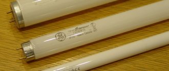
The design of the fluorescent lamp consists of:
- transparent elongated tube;
- two bases with two electrodes;
- a starter that starts working from ignition;
- electromagnetic choke;
- capacitor from the network.
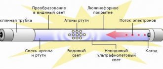
The bulb bulb is made of quartz glass. At the beginning of work in production, air is pumped out of the flask and a vacuum environment is created, and then it is filled with a mixture of inert gas with the addition of mercury. The latter must be in a gaseous state, because there is high pressure inside.
Transformation into a beam of light
The inside surface of the flask is coated with a phosphorescent substance, which converts the energy of ultraviolet light into a beam visible to the human eye.
An alternating mains voltage is connected to the ends of the electrodes of the light bulb. Tungsten filaments are coated with a heavy metal that emits electrons during operation. Cesium, barium, and thallium are mainly used. The choke is similar to a coil, which has a high magnetic permeability.
Electrode
The outer part of the electrode is soldered to the base. They begin to pump out all the air abundantly from the vessel using a rod, which is located in one of the legs with electrodes. Next, the vacuum environment begins to be filled with inert gases with mercury additives.
Certain types of electrodes are necessarily sprayed with an activating substance, such as barium, thallium or calcium oxide.
Standard plinth
Mercury atom
A little mercury is added to the fluorescent lamp, which turns into vapor when the discharge is ignited, and some argon, which helps increase the service life of the product and improve the conditions for revitalizing mercury atoms.
When the device is turned on, an electric discharge is supplied to the network, reviving the work of mercury vapor. A thin film of phosphor is activated by exposure to light from mercury vapor.
Glass tube
The glass tube can have different diameters. The intensity of the luminous flux can be different, it depends on the power of the fluorescent lamp. For its proper operation, a throttle type starter is required.
Attention! The temperature in the tube should not be above 55 degrees. Therefore, this lamp cannot be used in industrial hot shops
Classic electrical circuit
Phosphor
The most important part of a luminescent device will be the phosphor layer. The efficiency of phosphors—the ratio of the magnitude of emitted quanta to the magnitude of those absorbed to a greater extent—depends on the quality of the raw materials used in the production of the phosphor.
Operating principle of the device
Having supplied mains power to the lighting device, the voltage passes through the turns of the LL inductor and the filament made of tungsten single crystals.
Next, it is brought to the contacts of the starter and forms a glow discharge between them, while the glow of the gaseous medium is reproduced by heating it.
Since the device has another contact - a bimetallic one, it also reacts to changes and begins to bend, changing its shape. Thus, this electrode closes the electrical circuit between the contacts.
The magnitude of the current generated by the glow discharge varies from 20 to 50 mA, which is quite enough to heat up the bimetallic electrode, which is responsible for closing the circuit (+)
A closed circuit formed in the electrical circuit of a luminescent device conducts current through itself and heats the tungsten filaments, which, in turn, begin to emit electrons from their heated surface.
In this way, thermionic emission is formed. At the same time, the mercury vapor in the cylinder is heated.
The resulting flow of electrons helps to reduce the voltage applied from the network to the contacts of the starter by approximately half. The degree of glow discharge begins to fall along with the glow temperature.
The bimetal plate reduces its degree of deformation, thereby opening the chain between the anode and cathode. The current flow through this area stops.
A change in its indicators provokes the appearance of an electromotive force of induction inside the choke coil, in the conductive circuit.
The bimetallic contact instantly reacts by producing a short-term discharge in the circuit connected to it: between the tungsten LL filaments.
Its value reaches several kilovolts, which is quite enough to penetrate the inert environment of gases with heated mercury vapor. An electric arc is formed between the ends of the lamp, producing ultraviolet radiation.
Since this spectrum of light is not visible to humans, the lamp design contains a phosphor that absorbs ultraviolet radiation. As a result, the standard luminous flux is visualized.
When the current in the circuit changes or stops completely, changes in the magnetic flux through the surface of the plate occur proportionally, which limits this circuit and leads to the excitation of a self-inductive emf in this circuit
However, the voltage on the starter connected in parallel with the lamp is not enough to form a glow discharge; accordingly, the electrodes remain in the open position while the fluorescent lamp is on. Further, the starter is not used in the operating circuit.
Since the current must be limited after the glow is produced, an electromagnetic ballast is introduced into the circuit. Due to its inductive reactance, it acts as a limiting device that prevents lamp failure.
Operating principle
The action of the starter is inextricably linked with the operation of the entire fluorescent lamp and occurs in the following order:
- Before starting work, the electrodes are open.
- After applying voltage from the network, a glow discharge occurs inside the flask with current parameters of 20-50 mA.
- The discharge begins to act on the bimetallic electrodes, gradually heating them up.
- Under the influence of heating, the electrodes bend, after which the glow discharge stops and the electrical circuit inside the lamp is closed.
- An electric current begins to flow through a closed circuit, heating the inductor and the cathodes of the lamp itself.
- After the glow discharge ceases, gradual cooling of the bimetallic electrodes begins. As a result, they open, unbend and the chain breaks.
- All previous actions led to the appearance of a high pulse voltage acting on the inductor. The inductor itself has inductance, under the influence of which the lamp begins to light.
- Gradually the lamp glow increases and reaches normal. Since the starter is connected in parallel with the lamp, it no longer has enough voltage to create a new glow discharge, since all the current is spent on maintaining the glow. Therefore, the electrodes remain open, but the lamp still continues to work.
Types of starters for fluorescent devices
Depending on the operating algorithm, starting devices are divided into three main types: electronic, thermal and glow discharge. Despite the fact that the mechanisms have differences in design elements and operating principles, they perform identical options.
Electronic starter
The processes reproduced in the starter contact system are not controllable. In addition, the temperature regime of the environment has a significant impact on their functioning.
For example, at temperatures below 0°C, the heating rate of the electrodes slows down, and accordingly, the device will take longer to turn on the light.
Also, when heated, the contacts can be soldered to each other, which leads to overheating and destruction of the lamp coils, i.e. her damage.
Most models of electronic ballasts for LDS are based on the UBA 2000T microcircuit. This type of device allows you to eliminate overheating of the electrodes, thereby significantly increasing the service life of the lamp contacts and, accordingly, the period of its operation.
Even properly functioning devices tend to wear out over time. They retain the glow of the lamp contacts longer, thereby reducing its production life.
It was to eliminate this kind of shortcomings in the semiconductor microelectronics of starters that complex designs with microcircuits were used. They make it possible to limit the number of cycles of the process of simulating the closure of the starter electrodes.
In most samples presented on the market, the circuit design of the electronic starter is made up of two functional units:
- management scheme;
- high-voltage switching unit.
An example is the UBA2000T electronic ignitor chip from PHILIPS and the TN22 high-voltage thyristor from STMicroelectronics .
The operating principle of an electronic starter is based on opening the circuit by heating. Some samples have a significant advantage - the option of a standby ignition mode.
Thus, the opening of the electrodes is carried out in the required voltage phase and under the condition of optimal temperature indicators for heating the contacts.
The semiconductor elements of the electronic ballast must be suitable for key performance characteristics, namely, the ratio of the power value and the network voltage of the connected lighting device
It is important that if the lamp breaks down and unsuccessful attempts to start it of this type, the mechanism turns off if their number (attempts) reaches 7. Therefore, there can be no talk of premature failure of the electronic starter.
As soon as the light bulb is replaced with a working one, the device will be able to resume the LL start-up process. The only disadvantage of this modification is the high price.
In a circuit with a starter, as an additional method of reducing radio interference, balanced chokes with a winding divided into identical sections, with an equal number of turns wound onto a common device - the core, can be used.
Today, manufactured ballasts have a prefabricated rod design. The magnetic wire is cut from steel sheets. As a rule, such chokes have two symmetrical windings
All areas of the coil are connected in series order to one of the lamp contacts. When turned on, both of its electrodes will operate under the same technical conditions, thus reducing the degree of interference.
Thermal view of the starter
The key distinguishing characteristic of thermal igniters is the long start-up period of the LL. During operation, such a mechanism uses a lot of electricity, which negatively affects its energy-consuming characteristics.
Thermal starter is also called thermobimetallic. Heating of the contacts occurs at a slower rate, which effectively affects the operation of the lighting device in a low-temperature environment
As a rule, this type is used in low temperature conditions. The operating algorithm differs significantly from analogues of other types.
In the event of a power failure, the electrodes of the device are in a closed state; when applied, a pulse with a high voltage is formed.
Glow discharge mechanism
Starting mechanisms based on the glow discharge principle have bimetallic electrodes in their design.
They are made of metal alloys with different coefficients of linear expansion when the plate is heated.
The disadvantage of the glow discharge igniter is the low level of the voltage pulse, which is why the LL ignition is not sufficiently reliable
The possibility of igniting the lamp is determined by the duration of the previous heating of the cathodes and the current flowing through the lighting device at the moment the starter contact circuit opens.
If the starter does not light the lamp on the first pull, it will automatically repeat attempts until the lamp lights up.
Therefore, such devices are not used in low temperatures or unfavorable climates, for example, high humidity.
If the optimal heating level of the contact system is not provided, the lamp will take a long time to ignite or will be damaged. According to GOST standards, the time spent by the starter on ignition should not exceed 10 seconds.
Starting devices that perform their functions using the thermal principle or a glow discharge are necessarily equipped with an additional device - a capacitor.
Possible faults
When using any lighting source, the question of repairing it and replacing failed elements always arises.
One of the reasons for the fluorescent lamp not igniting may be a faulty starter, the malfunction of which can be expressed as:
- The lamp does not light up;
- There is a glow at the ends of the lamp, but the lamp does not light up.
To replace the starter, you need to perform simple operations:
- Turn off the lamp;
- Remove the lampshade or other protective element of the lamp;
- Remove the faulty element - starter;
- Insert a new device into the base;
- Reassemble the lamp in reverse order;
- Turn on the lamp.
Replacing the starter is not difficult when there is a spare one, but if there is no such thing, then you need to make sure that the one removed from the lamp is exactly the element due to which the lamp does not burn. Its functionality can be checked in a simple way.
It is necessary to turn on the incandescent light bulb in series with the starter and apply voltage to them. If the starter is working, the light will light up and periodically turn off, and a characteristic click will be heard inside the starter. If the light does not light up, or lights up and does not blink, then the starter is faulty and definitely needs to be replaced.
Theoretically, it is believed that the service life of a starter is equivalent to the operating time of the lamp it lights. However, it must be taken into account that with increasing service life of the device, the intensity of the glow discharge voltage for starters of this type decreases, which affects the operation of the latter. However, all manufacturers of fluorescent lamps recommend replacing starters at the same time as replacing lamps.
The role of the capacitor in the circuit
As noted earlier, the capacitor is located in the casing of the device parallel to its cathodes.
This element solves two key problems:
- Reduces the degree of electromagnetic interference created in the radio wave range. They arise as a result of contact between the system of starter electrodes and those formed by the lamp.
- Affects the ignition process of a fluorescent lamp.
This additional mechanism reduces the magnitude of the pulse voltage generated when the starter cathodes open and increases its duration.
The capacitor reduces the likelihood of contact sticking. If the device does not have a capacitor, the voltage across the lamp increases quite quickly and can reach several thousand volts. Such conditions reduce the reliability of lamp ignition.
Since the use of a suppression device does not allow achieving complete leveling of electromagnetic interference, two capacitors are introduced at the input of the circuit, the total capacitance of which is at least 0.016 μF. They are connected in series order with the middle point grounded.
Electronic ballast
The disadvantages of the electronic ballast circuit necessitated the search for a more optimal connection method. During the research, a method involving electronic ballast was invented. In this case, it is not the mains frequency (50 Hz) that is used, but high frequencies (20 – 60 kHz). It is possible to get rid of the flashing light that is harmful to the eyes.
Externally, the electronic ballast is a block with terminals exposed to the outside. The inside of the device contains a printed circuit board on which the entire circuit can be assembled. The unit is small in size, thanks to which it fits into the housing of even a small lighting device. Switching on is much faster compared to the EMPA standard. The operation of the device does not cause acoustic discomfort. This connection method is called starterless.
It is not difficult to understand the principle of operation of a device of this type, since there is a diagram on its reverse side. It shows the number of lamps for connection and explanatory notes. There is information about the power of the light bulbs and other technical parameters of the device.
The connection is made as follows:
- The first and second contacts are connected to a pair of lamp contacts.
- The third and fourth contacts are directed to the remaining pair.
- Power is supplied to the input.
Using Voltage Multipliers
This option allows you to connect a fluorescent lamp without using an electromagnetic balance. Usually used to increase the service life of light bulbs. The connection diagram for burnt-out lamps makes it possible for the light sources to work for some more time, provided that their power is no more than 20 - 40 W. Filaments are allowed both suitable for work and burnt out. In any case, the thread leads must be short-circuited.
As a result of rectification, the voltage doubles, so the light bulb turns on almost instantly. Capacitors C1 and C2 are selected based on an operating voltage of 600 Volts. The disadvantage of capacitors is their large size. As capacitors C3 and C4, preference is given to mica devices rated at 1000 Volts.
Fluorescent lamps are not compatible with direct current. Very soon, so much mercury accumulates in the device that the light becomes noticeably weaker. To restore the brightness of the glow, change the polarity by turning the bulb over. Alternatively, you can install a switch so you don't have to remove the lamp every time.
Connection without starter
The method using a starter involves prolonged heating of the light bulb. In addition, this part must be changed frequently. A scheme where the electrodes are heated using old transformer windings allows you to do without a starter. The transformer acts as ballast.
Bulbs used without a starter must be marked RS (quick start). A light source started through a starter is not suitable, since its conductors take a long time to heat up and the spirals burn out quickly.
Serial connection of two light bulbs
In this case, it is necessary to connect two fluorescent lamps with one ballast. All devices are connected in series.
To carry out electrical work you will need the following parts:
- induction throttle;
- starters (2 units);
- fluorescent light bulbs.
The connection is made in the following order:
- We connect starters to each light bulb. The connection is made in parallel. The connection point is the pin input at the ends of the lighting device.
- We direct free contacts to the electrical network. We use a choke for connection.
- We connect capacitors to the contacts of the light source. They will allow you to reduce the intensity of interference in the network and compensate for power reactivity.
Main disadvantages of starters
The main disadvantage of starters is the unreliability of the design. Failure of the trigger mechanism provokes a false start - several flashes of light are visualized before the start of a full-fledged light flux. Such problems reduce the life of the tungsten filaments of the lamp.
Starters generate significant energy losses and reduce the efficiency of the lamp device. Disadvantages also include voltage dependence and significant variation in the response time of the electrodes
With fluorescent lamps, an increase in operating voltage is observed over time, while with a starter, on the contrary, the longer the service life, the lower the glow discharge ignition voltage. Thus, it turns out that the switched on lamp can provoke its operation, causing the light to go out.
The open contacts of the starter turn on the light again. All these processes are carried out in a split second and the user can only observe flickering.
The pulsating effect causes irritation of the retina and also leads to overheating of the inductor, reducing its service life and failure of the lamp.
The same negative consequences are expected from a significant spread of contact system time. It is often not enough to fully preheat the lamp cathodes.
As a result, the device lights up after reproducing a number of attempts, which are accompanied by an increased duration of the transition processes.
If the starter is connected to a single-lamp circuit, then there is no way to reduce the light pulsation.
In order to reduce the negative effect, it is recommended to use this kind of circuit only in rooms where groups of lamps (2-3 samples each) are used, which must be included in different phases of a three-phase circuit.
Elements of “ignition” of light
The starter of various modifications ignites light sources that are powered by alternating current mains with a frequency of 50 Hz.
For this purpose, the lamp device has a ballast. In devices with glow discharge, after activation of the light source, increased voltage will begin to flow to the contacts.
The component itself is presented in the form of a small glass flask filled with gas. The flask itself is located in the inner part of the housing made of plastic or metal. In the lower part there is equipment consisting of two electrodes that come into contact with the lamp wires. Some models have a window at the top.
It is worth noting that it is the starters that most often break, after which the lamp cannot be turned on. But replacing them is not difficult if you know how to do it.
This component has the following functions:
- it starts first when connected to the network;
- responsible for heating the electrode;
- increases the current supply to the illuminator;
- closes and opens bimetallic plates;
- transmits current to the inductor.
If a part fails, the lamp simply will not turn on and begin to shine . Moreover, if a direct connection is made, the life of the lighting components is reduced. Starters are selected in accordance with the connection diagram.
Explanation of marking values
There is no generally accepted abbreviation for starter models of domestic and foreign production. Therefore, we will consider the basics of notation separately.
Decoding the value 90C-220 looks like this: a starter operating with luminescent samples, the power of which is 90 W, and the rated voltage is 220 V (+)
According to GOST, the decoding of the alphanumeric values [ХХ][С]-[ХХХ] printed on the device body is as follows:
- [XX] – numbers indicating the power of the light-reproducing mechanism: 60 W, 90 W or 120 W;
- [C] – starter;
- [ХХХ] – voltage used for operation: 127 V or 220 V.
To implement lamp ignition, foreign developers produce devices with various designations.
The electronic form factor is produced by many companies.
The most famous on the domestic market is Philips , which produces the following types of starters:
- S2 are designed for power 4-22 W;
- S10 - 4-65 W.
OSRAM is focused on producing starters for both single and serial connection of lighting devices . In the first case, this is marked S11 with a power limit of 4-80 W, ST111 - 4-65 W. And in the second, for example, ST151 - 4-22 W.
Manufactured starter models are presented in a wide range. The key parameters taken into account during selection are commensurate values with the characteristics of fluorescent lamps.
Variety of lighters
Today, several types of igniters are used:
smoldering row. Designed for light bulbs with bimetallic electrodes. These types of models are used most often, as they have a simplified design. In addition, they require a small amount of time to light the lamp;
Smolder row starter
thermal. They are characterized by a longer period of ignition of the light source. But in such a situation, the electrodes take longer to heat up, and this has a positive effect on the performance of the light bulb. Also, thermal igniters are characterized by a more complex structure and therefore consume more energy for their operation;
semiconductor. They operate on the principle of a key. When they are heated, the electrodes open, resulting in the formation of a pulse in the bulb and the light bulb turns on.
In order to make the right choice in favor of one model or another, you need to know not only the principle of their design, but also the technical characteristics. Let's consider the most popular and sought-after starter options, which are actively used to activate fluorescent lamps.
What to look for when choosing?
When choosing a launcher, it is not enough to base it on the name of the developer and the price range, although these factors should also be taken into account, because... indicate the quality of the device.
In this case, reliable devices that have proven themselves in practice win. It is worth paying attention to such companies: Philips , Sylvania and OSRAM .
Starter FS-11 brand Sylvania. Suitable for fluorescent lamps with a power of 4-65 W. Can be used on AC power. Works on the glow discharge principle
The most basic operational parameters of the starter are the following technical features:
- Ignition current. This indicator should be higher than the operating voltage of the lamp, but not lower than the power supply.
- Base voltage. When connected to a single-lamp circuit, a 220 V device is used, and a two-lamp circuit uses a 127 V device.
- Power level.
- The quality of the housing and its fire resistance.
- Operational life. Under standard operating conditions, the starter must withstand at least 6000 starts.
- Duration of cathode heating.
- Type of capacitor used.
It is also necessary to take into account the inductive reaction of the coil and the rectification coefficient, which is responsible for the ratio of reverse to forward resistance at a constant voltage.
Additional information about the design, operation and connection of the ballast mechanism of fluorescent lamps is presented in this article.
Review of popular models
Below is an overview of the most popular models from leading manufacturers of these devices:
Phillips starters
Manufactured in the Netherlands and of the highest quality , the body is made of a fire-resistant type of polycarbonate, which guarantees safety during use.
Model S-2 is used to ignite low-voltage lamps or high-voltage varieties that are connected in series and operate at a power of 4-22W.
Model S-10 is more universal and is used for high-voltage light sources operating at any power level.
The price for such starters is about 10 rubles.
Osram starters made in Russia
They also meet all quality standards; the fire-resistant body is made of macrolon. The design includes a roll-type capacitor made from foil.
Model ST111 is used to connect single lamps with a power in the range of 4-80W when operating from a 220V AC power supply.
Model ST151 is used when connecting to a 110V or 127V network, can also be used for serial connection to 220V, designed for lamps with a power of no more than 22W.
The cost of such starters is about 6 rubles.
What kind of markings are there?
At this point in time, starters designed for fluorescent lamps may differ from each other in technical parameters of rectification, as well as in size. In this regard, there are the following markings for this type of parts:
- S2. Starter S2 is suitable for 2P sockets. Technical characteristics in this situation for the rectification parameter do not exceed 2.5 microns;
- S10. Such parts are suitable for 3P bases.
Note! The marking of this part for fluorescent lamps according to GOST is always shown on its body.
Let us now consider in more detail the most popular models of this type of product. Each variety must meet GOST standards. Their service life, as well as the quality of work, depends on this.
Service life, repair and replacement
The starter's service life is designed for approximately 6,000 starts, which is often above average. As a result of prolonged use, voltage levels decrease. In addition, the electrode contacts often cause a short circuit when the light device is turned on, causing it to fail. In order to light the lamp, it is necessary to open the ignitor contacts. As a result, the light will begin to flash. It is necessary to replace the starter in time, otherwise troubles cannot be avoided. Not only will you have to buy individual parts for the light fixture, but you will also most likely have to completely replace it. Therefore, changing the lamp will cost much more than simply replacing the starter.
Parameters and markings
When choosing a starting device, you need to pay special attention to its parameters and technical characteristics:
- Service life established by manufacturers. The leaders in this indicator are Osram and Phillips, whose products can withstand at least 6 thousand on and off cycles. However, in practice, this parameter is not always observed for objective reasons, for example, due to surges in mains voltage.
- Operating temperature range. Usually set within the range of 5-55 0 C. If you need to use lamps outside the established standards, then for these cases you will need special starters with a much higher cost.
- The time period during which the cathodes are fully heated. This factor determines the period that the bimetallic electrodes are in the closed position. This indicator may vary significantly among different manufacturers.
- Varieties and modifications of capacitors involved in a particular device. The service life of the device largely depends on its design.
- Rated operating voltage. This characteristic must be checked, since a device designed for 127 V and connected to a 220 V lamp will immediately fail.
All parameters are displayed on the device label. For domestic devices it looks like this:
- The letter "C" indicates that it belongs to the starter category.
- The numbers in front of the letter “C” indicate the power of the lamp for which this starter is intended.
- The numbers behind the letter “C” correspond to the operating voltage parameters, for example, 127 or 220.
Thus, the marking 60C-220, given as an example, indicates a device that is a starter for a 60 W fluorescent lamp operating on a 220 V network.
Execution options
There is a wide variety of electroluminescent lamps, but they can all differ in:
- form of execution;
- type of ballast;
- internal pressure.
The design can be the same as that of conventional fluorescent lamps - a linear tube or a tube in the shape of the Latin letter U. Compact options have been added to them, made to fit a familiar base using various spiral bulbs.
Ballast is a device that stabilizes the operation of the product. Electronic and electromagnetic types are the most common connection schemes.
Internal pressure determines the area of use of the products. Low-pressure lamps or energy-saving samples have been used for domestic purposes or public places. In industrial premises or places with reduced requirements for color rendering, high-pressure units are used.
To assess the ability of lighting, an indicator of the lamp power and its light output is used. Many more different classification parameters and design options can be given, but their number is constantly increasing.
Blitz tips
If necessary, choose a replacement for a failed starter as follows:
- Pay attention to the lamp supply voltage;
- Determine the required power of the device;
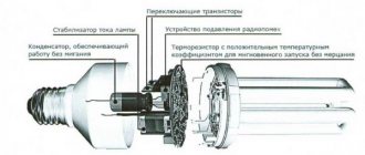
- Choose a manufacturer based on pricing policy and required reliability.
Technologies do not stand still. The starter is now mounted directly into the base of fluorescent lamps with a standard socket; these lamps are called “economy lamps”. They are similar in their operating principles to fluorescent lamps, only their appearance is greatly changed.