Agree: there is no need to buy and install unnecessary devices, without which the lighting system can work. Such questionable devices include a choke for fluorescent lamps. You don’t know whether it is needed in the connection diagram or whether you can do without it?
We will help you resolve the issue that has arisen. The article discusses in detail the features, purpose of the throttle and the functions it performs. There is a photo and a connection diagram that will help you assemble the fluorescent lamp yourself and start it up by correctly connecting all the components into the electrical circuit.
To help the home craftsman, we have selected a number of videos containing recommendations on connecting fluorescent light bulbs, as well as on choosing the right inductor depending on the type of lamp.
Principle of operation
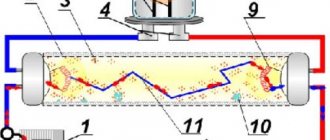
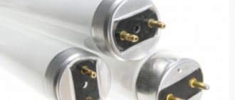
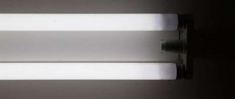
In its classic form, a FL (fluorescent lamp) is a glass tube with a phosphor applied to its inner surface. An inert gas mixed with mercury vapor is placed inside the tube at reduced pressure. Tungsten electrodes (cathodes) are soldered into the ends of the product.
The principle of operation and structure of a fluorescent lamp
In operating condition, after a high voltage breakdown of the gas, a current flows through the lamp, resulting in UV radiation invisible to the human eye. Under the influence of this radiation, the phosphor generates a luminous flux in the visible range, the color shades of which can vary depending on the type of phosphor.
The current during a gas discharge changes like an avalanche and a series-connected load is used to limit it.
Note! To start and maintain the operating mode of the LL, special ballasts (ballasts) are used. Such equipment is often called ballast.
Main functions
It is not possible to connect fluorescent light sources directly to the electrical network. There are the following reasons for this:
- to create a persistent discharge in a fluorescent lamp, it is necessary to preheat its electrodes and apply a starting pulse to them;
- Since gas-discharge light sources have a negative differential resistance, they are characterized by an increase in current strength after entering the operating mode. It must be limited to prevent the light source from failing.
Based on the reasons described above, it is necessary to use ballasts.
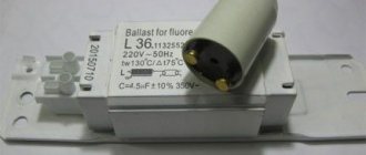
Electromagnetic type ballasts
Electromagnetic type ballasts
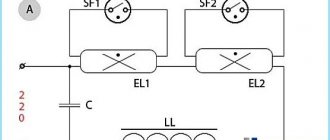
The electrical circuit for powering a LL using conventional ballasts is shown in Fig. 1.
Fig.1. Electrical circuit for powering a LL using conventional ballasts
A starter is a device designed for short-term automatic switching on and off of an electrical circuit.
There are various designs of starters - glow discharge, thermal, electronic, electromagnetic. The most common are glow discharge starters, which use bimetallic plates.
Fig.2. Starter for starting fluorescent lamps
When a glow discharge occurs in the starter, such plates heat up and close the circuit. After the circuit is closed, the discharge stops, the electrodes cool down and open. The starter parameters are selected in such a way that the glow discharge voltage is higher than the operating voltage of the LL and lower than the minimum mains voltage.
Prices for starters for fluorescent lamps
Prices for starters for fluorescent lamps
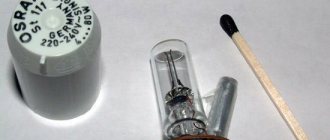
The inductor is a regular inductor wound around a core. To prevent the appearance of eddy currents in the core, it is assembled from separate thin plates. The permissible power of the throttle must correspond to the power of the LL. Otherwise the lamp will not turn on.
Fig.3. Choke for fluorescent lamps
When the starter short-circuits, a large current passes through the LL electrodes, heating the filaments of these electrodes. and causing thermionic emission. As a result of this emission, electron clouds are formed near the electrodes, facilitating breakdown and the appearance of a discharge.
When the starter contacts open, according to the phenomenon of self-induction, a powerful voltage pulse is generated in the circuit, the magnitude of which is proportional to the inductance of the inductor. Under the influence of this pulse, gas breakdown occurs and a glow discharge occurs, which can turn into an arc. But the presence of a balanced resistance in the form of a choke limits the amount of current flowing through the device.
Thus, the throttle plays a dual role:
- The high-voltage voltage pulse generated by the choke when the starter opens the electrical circuit ensures gas breakdown and ignition of the lamp.
- In the LL combustion mode, the inductive reactance of the choke ensures that the operating voltage is maintained at the lamp electrodes, providing a glow discharge.
In Fig. 1, the compensating capacitor C1, connected at the input of the LL power supply circuit, is designed to increase the power factor (cos φ). To reduce the effect of radio interference, a small capacitor (C2) is connected in parallel to the starter contacts. This capacitor also allows you to change the transient process in the circuit and increase the power of the voltage pulse.
Turning on devices with burnt out coils
If your closet is covered in dust from burnt-out fluorescent lamps that you have no intention of disposing of, don’t rush to throw them away. Such devices can still serve you if you know how to hold a soldering iron in your hands. To implement this idea, you will need two absolutely non-deficient diodes and two capacitors:
Connection diagram for LDS with burnt coils
How does this scheme work? A bridge assembled on diodes VD1, VD2, C1, C2 is a simple multiplier that doubles the voltage. In order for a glow discharge to begin at 400 - 450 V, it is not at all necessary to heat the electrodes. Once the lamp starts, ballast L1 will limit the current through the lamp to operating levels.
If you decide to repeat this circuit, then pay attention to the fact that the capacitors must be non-polar paper, and the diodes are designed for a reverse voltage of at least 300 V. An ordinary inductor is used as a ballast, the power of which is equal to the power of the lamp. If the throttle is very tight, but lighting must be organized at any cost, you can use an ordinary incandescent light bulb as a ballast, the power of which is equal to the power of the LDS. But such a replacement will greatly reduce the efficiency of the entire device, and therefore is not always justified.
The following version of the lamp is useful in case you have at your disposal two LDS of the same type, in which one spiral has burned out (usually this happens). To implement it, you will need a choke with a power twice as high as the rating of each light bulb, and a standard 220 V starter:
Turning on two LDS with burnt out coils
Here the starter heats one coil in each lamp, which are connected in series. This is quite enough to start most gas-discharge devices. There is another application for this scheme. It is convenient if you do not have two chokes for the required power, but have one for double it. It is quite obvious that LDS with working spirals will also work in this scheme.
electronic ballasts
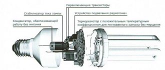
Electronic ballast (EPG) is a complex device with many electronic elements. Block diagram of such a device is shown in Fig. 4.
Fig.4. Block – electronic ballast circuit (EPG)
The main difference between electronic ballasts and conventional ballasts is the presence of an inverter, which, using transistor switches, converts a mains voltage of 50 Hz into a voltage with a frequency of 30-40 kHz. Thanks to this, the size and dimensions of this device are reduced. When the circuit is turned on, the LL cathodes heat up, electron “clouds” form near them, and a resonant voltage of about 600 V appears on a capacitor connected in parallel with the lamp, which is sufficient to ignite the lamp.
Fig.5. Electronic ballast device for fluorescent lamps
After the LL is turned on, the voltage across it drops to operating level, and the current is limited by the balanced choke.
How to replace
Recently, very often such an operation is caused by the need to replace magnetic chokes with electronic ones. This process is quite simple and straightforward, but must also be performed by specialist electricians. The process of replacing ballast from magnetic to electronic:
- Turn off power to the device.
- Open the lamp, remove the bulb and ballast casing.
- Using wire cutters, cut the power (brown) and neutral (blue) wires going into the device.
- Cover the wires with wire nuts.
- Use wire cutters to cut off the wires and remove the magnetic ballast.
- Attach the electronic ballast to the place where the magnetic one was.
- Connect the power and neutral wires to the corresponding ballast wires.
- Secure the wires with wire nuts.
- Return the lamp bulb and throttle housing back.
- Turn on the power to the lamp.
Properly installed and functioning electric lighting ballasts should last a long time, providing safe, well-regulated current to lighting fixtures without annoying flickering or humming.
Daylighting scheme
The choke, although it plays an important role in the installation of LL today, is no longer indispensable; its place has been taken by an electronic ballast (electronic ballast). Property owners planning to install such lighting should take into account that on July 1, 2022, the use of tubular LLs, as well as mercury lamps, is prohibited in Russia, and from the beginning of 2022, fluorescent and sodium lamps will be prohibited.
Advantages and disadvantages
Comparative characteristics of two types of ballasts are given in the table.
| № | PRA | electronic ballasts |
| 1 | Simple, clear design | Complex circuit |
| 2 | Low price | Relatively high price |
| 3 | Large weight and dimensions | Compact device |
| 4 | Presence of flicker (100 Hz) | No flicker |
| 5 | Long start-up time | Instant launch |
| 6 | Difficulty starting at low temperatures | No difficulties |
| 7 | Low efficiency and cos φ | High efficiency |
| 8 | Doesn't work at low voltage | Wide voltage range |
| 9 | LL wear out quickly | LL work full term |
Prices for Electronic ballasts for fluorescent lamps
Prices for electronic ballasts for fluorescent lamps
Connect it yourself
You can also make an electromagnetic choke yourself. But this is rarely done. Much more often, craftsmen restore ballasts on their own, since it is not always possible to purchase the right model (it is especially difficult to find it in the outback).
The protective cover and two halves of the core are removed from the device (they are L-shaped). Then the winding is removed. If for some reason it is difficult to remove the turns of wire, they can be cut off using a hacksaw.
For a new winding, you can use copper wire with a diameter of 0.64-0.8 mm. A thousand turns are wound in bulk without interlayer insulation.
The greater the throttle power, the easier it is to restore it. Low-power (and therefore small-sized) chokes are filled with compound, which makes the process of restoring them very problematic.
Rewinding the throttle takes no more than two hours.
A comparison of the two types of chokes allows us to conclude that electronic ballasts have an undoubted advantage. They are lighter and smaller in size. Such characteristics facilitate the creation of miniature lighting devices, the need for which is steadily increasing.
Repair
If a lamp with an LL powered by a ballast fails, along with other elements of the circuit, it is necessary to check the performance of the inductor. The following malfunctions are possible:
- overheat;
- winding break;
- closure (full or interturn).
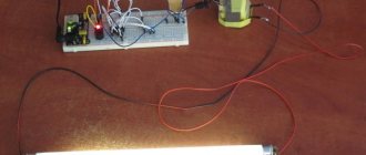
To check the throttle, you need to assemble the circuit shown in Fig. 6.
Fig.6. Circuit for checking the throttle
When the circuit is turned on, three options are possible: the lamp is on, the lamp is off, the lamp is blinking.
In the first case, there appears to be a short circuit in the throttle. In the second case, there is obviously a break in the winding. In the third case, it is possible that the inductor is intact and it is necessary to look for a fault in another element of the circuit. To be completely sure, you need to let the circuit run for 0.5 hours. If it turns out that the inductor is very hot, this indicates a short circuit between the turns of the winding.
Specifications
The technical features of chokes that you should definitely pay attention to when choosing a light source are the following:
- Purpose. In a luminescent device, the inductor coil creates the necessary impulse so that metal vapors can burn in the device, and it also maintains the required power value during operation of the device.
- Power. The main technical parameter of the limiter is its power value. The performance of all other parameters and the lamp as a whole depends on it. Based on power indicators, these parameters will be different for each lamp limiter. According to the power level, limiters are divided into three large categories: B, C, and D. The name of the limiters depends on which category they belong to.
- Self-induction coefficient. Due to the inductance of the inductor, the power of electricity that falls on the conductive contacts of the lamp.
Self-induction coefficient.
Starting LL without throttle
Circuits for turning on a LL without a choke, as a rule, are a DC power source in the form of a multiplier. One of the circuits of such a source is shown in Fig. 7. An ordinary incandescent lamp is used as a current limiter in the circuit.
Fig.7. Circuit for turning on fluorescent lamps without a choke
In such a circuit, the voltage across the LL reaches 700 V in approximately 25 ms.
Connection without ballast
If necessary, gas-discharge light sources can be connected to the power supply without electromagnetic or electronic ballast. The diagram of such a connection is shown below.
Throttleless connection method
To implement such a connection you will need:
- fluorescent lamp - 40 W and incandescent lamp - 60 W (the latter will work as a ballast resistance);
- two capacitors 0.47 uF 400 V (play the role of a multiplier);
- diode bridge KTs404A or similar, you can use four diodes designed for a current of at least 1 A and a reverse pulse voltage of 600 V.
This circuit is inferior in its parameters to connection using an electromagnetic choke and electronic ballasts. It is provided for informational purposes only.
Comparison of chokes for different types of lamps
Chokes are used in gas-discharge lamps of various types. In any case, they serve to limit the operating current of the lamp. However, such chokes are not always interchangeable.
Thus, Dnat and DRL lamps operate in arc discharge mode, while LL lamps operate in glow discharge mode. Different operating modes require different throttle characteristics. In addition, the difference is that the choke as a voltage source for ignition is used only in LL.
Note! In Dnat lamps, a special pulse device (IZU) is used for starting, and DRL lamps are started directly from a 220 V network.
Prices for choke for fluorescent lamps
Prices for choke for fluorescent lamps
Tandem connection
Below is a diagram where two fluorescent type lamps are connected in series.
Tandem connection diagram
The operating principle of the presented circuit does not differ from a standard connection, the only difference is in the parameters of the starters. For a two-lamp connection, starters are used whose “breakdown” voltage is 110 V (type S2), for a single-lamp connection - 220 V (type S10).
Starters S10 and S2 for 220 and 110 V respectively