Are you interested in why an electronic ballast module is needed for fluorescent lamps and how it should be connected? Proper installation of energy-saving lamps will extend their service life many times over, right? But you don’t know how to connect electronic ballasts and whether it is necessary to do so?
We will tell you about the purpose of the electronic module and its connection - the article discusses the design features of this device, thanks to which the so-called starter voltage is formed, and the optimal operating mode of the lamps is maintained.
Schematic diagrams for connecting fluorescent light bulbs using an electronic ballast are provided, as well as video recommendations for the use of such devices. Which are an integral part of the gas-discharge lamp circuit, despite the fact that the design of such light sources may differ significantly.
Designs of ballast modules
The designs of industrial and household fluorescent light bulbs are usually equipped with electronic ballast modules. The abbreviation reads quite clearly - electronic ballast.
Old style electromagnetic device
Considering the design of this device from the series of electromagnetic classics, one can immediately note an obvious drawback - the bulkiness of the module.
True, designers have always sought to minimize the overall dimensions of EMP. To some extent this was successful, judging by modern modifications already in the form of electronic ballasts.
A set of functional elements of an electromagnetic ballast. Its components, as you can see, are only two components - a choke (the so-called ballast) and a starter (discharge formation circuit)
The bulkiness of the electromagnetic design is due to the introduction of a large inductor into the circuit - a mandatory element designed to smooth out the mains voltage and act as ballast.
In addition to the choke, the EMP circuit includes starters (one or two). The dependence of the quality of their work and the durability of the lamp is obvious, since a defect in the starter causes a false start, which means an overcurrent on the filaments.
This is what one of the design options for the starter of the ballast control electromagnetic module of fluorescent lamps looks like. There are a lot of other designs where there is a difference in size and body materials
Along with the unreliability of the starter, fluorescent lamps suffer from the strobing effect. It appears in the form of flickering with a certain frequency close to 50 Hz.
Finally, the ballast provides significant energy losses, that is, it generally reduces the efficiency of fluorescent lamps.
Improvement of the design to electronic ballasts
Since the 1990s, fluorescent lamp circuits have increasingly been supplemented with an improved ballast design.
The basis of the modernized module was made up of semiconductor electronic elements. Accordingly, the dimensions of the device have been reduced, and the quality of work is noted at a higher level.
The result of modification of electromagnetic regulators is electronic semiconductor devices for starting and adjusting the glow of fluorescent lamps. From a technical point of view, they have higher performance indicators
The introduction of semiconductor electronic ballasts led to the almost complete elimination of the shortcomings that were present in the circuits of devices of outdated format.
Electronic modules show high-quality stable operation and increase the durability of fluorescent lamps.
Higher efficiency, smooth dimming, increased power factor - all these are the advantageous characteristics of new electronic ballast modules.
In Vasmer Max's dictionary
As a prefix in nominal additions, it has an intensifying meaning, for example. prastary “most ancient”, or denotes a higher degree; in terms of kinship - more distant kinship (great-grandfather, great-grandson); also appears in the meaning. “the beginning of something”: ancestral frames “red inserts on the shoulders of a woman’s shirt”; may denote a transition to another state: ancestral pond “heavy rain” (Potebnya, RFV 4, 219; Srezn. II, 1342). Connected by alternating vowels with pro (see), prefix and preposition. in verb. additions (Rozvadovsky RS 2, 94; Brugman, Grdr. 2, 2, 873). Wed. Ukrainian, Belarusian, other Russian, Old Slavic, Bulgarian, Serbo-Croatian Proto-, Slovenian, Czech, Slavic, Polish, V. Luzh. pra-.Cognate lit. prõ, sentence with wine “past”, própernai “in the year before last”, Old Prussian. prābutskas “eternal”, Old Indian рrā- along with рra- (Zubatiy, WZKМ 4, 89 et seq.; Solmsen, KZ 35, 468), prātár “early, in the morning”, Homer. πρωΐ, att. πρῴ – the same, πρωπέρυσι “two years ago”, lat. рrō “before”, d.-v.-n. fruо “early” (Trautman, Germ. Lautg. 22; BSW 229 et seq.; Ar. Sprd. 411; Brugman, Grdr. 2, 2, 873; M.–E. 3, 400; Hoffman, Gr. Wb. 286; Walde-Hofm. 2, 364 et seq.)
What does the device consist of?
The main components of the electronic module circuit are:
- rectifier device;
- electromagnetic radiation filter;
- power factor corrector;
- voltage smoothing filter;
- inverter circuit;
- throttle element.
The circuit design provides for one of two variations - bridge or half-bridge. Designs that use a bridge circuit typically support high-power lamps.
Ballast control modules made according to a bridge circuit are designed for approximately such light devices (with a power of 100 watts or more). Which, in addition to power support, has a positive effect on the characteristics of the supply voltage
Meanwhile, mainly modules built on the basis of a half-bridge circuit are used as part of fluorescent lamps.
Such devices are more common on the market compared to pavement ones, since for traditional use, lamps with a power of up to 50 W are sufficient.
Features of the device
Conventionally, the functioning of electronics can be divided into three operating stages. First of all, the function of preheating the filaments is turned on, which is an important point in terms of the durability of gas light fixtures.
This function is seen as especially necessary in low-temperature environments.
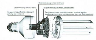
View of the working electronic board of one of the models of a ballast module based on semiconductor elements. This small, lightweight board completely replaces the functionality of a massive inductor and adds a number of improved features.
Then the module circuitry starts the function of generating a high-voltage impedance pulse - a voltage level of about 1.5 kV.
The presence of a voltage of this magnitude between the electrodes is inevitably accompanied by a breakdown of the gaseous medium of the fluorescent lamp cylinder - the ignition of the lamp.
Finally, the third stage of the module circuit is connected, the main function of which is to create a stabilized gas combustion voltage inside the cylinder.
The voltage level in this case is relatively low, which ensures low energy consumption.
Schematic diagram of the ballast
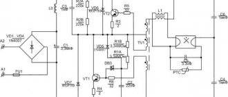
As already noted, a frequently used design is an electronic ballast module assembled using a push-pull half-bridge circuit.
Schematic diagram of a half-bridge device for starting and adjusting the parameters of fluorescent lamps. However, this is far from the only circuit solution that is used for the manufacture of electronic ballasts
This scheme works in the following sequence:
- The mains voltage of 220V is supplied to the diode bridge and filter.
- A constant voltage of 300-310V is generated at the filter output.
- The inverter module increases the voltage frequency.
- From the inverter, the voltage passes to a symmetrical transformer.
- At the transformer, due to the control keys, the necessary operating potential for the fluorescent lamp is formed.
Control keys installed in the circuit of two sections of the primary and on the secondary winding regulate the required power.
Therefore, the secondary winding generates its own potential for each stage of lamp operation. For example, when heating the filaments one, in the current operating mode the other.
Let's consider the schematic diagram of a half-bridge electronic ballast for lamps with a power of up to 30 W. Here the mains voltage is rectified by an assembly of four diodes.
The rectified voltage from the diode bridge goes to the capacitor, where it is smoothed in amplitude and filtered from harmonics.
The quality of circuit operation is influenced by the correct selection of electronic elements. Normal operation is characterized by the current parameter at the positive terminal of capacitor C1. The duration of the lamp ignition pulse is determined by capacitor C4
Next, through the inverting part of the circuit, assembled on two key transistors (half-bridge), the voltage coming from the network with a frequency of 50 Hz is converted into a potential with a higher frequency - from 20 kHz.
It is already supplied to the terminals of the fluorescent lamp to ensure operating mode.
A bridge circuit operates on approximately the same principle. The only difference is that it uses not two inverters, but four key transistors. Accordingly, the scheme becomes somewhat more complicated, additional elements are added.
An inverter circuit assembly assembled using a bridge circuit. Here, not two, but four key transistors are involved in the operation of the node. Moreover, preference is often given to semiconductor elements of the field structure. In the diagram: VT1...VT4 - transistors; Tp—current transformer; Up, Un - converters
Meanwhile, it is the bridge version of the assembly that ensures the connection of a large number of lamps (more than two) on one ballast. As a rule, devices assembled using a bridge circuit are designed for load power of 100 W and above.
This is interesting
Currently, electronic ballasts are installed not only with gas-discharge light sources, but also with halogen and LED lamps. In this case, you cannot use one device designed for one type of lamp to another lamp. Firstly, they won’t fit the parameters. Secondly, they have different schemes.
When choosing an electronic ballast, it is necessary to take into account the power of the lamp in which it will be installed.
The optimal model option is devices with protection against non-standard operating modes of the light source and against their deactivation.
Be sure to pay attention to the position in the passport or instructions, which indicates in what weather and climatic conditions the electronic ballast can operate. This affects both the quality of operation and service life.
Connection options for fluorescent lamps
Depending on the circuit solutions used in the design of ballasts, connection options can be very different.
If one device model supports, for example, connecting one lamp, another model can support the simultaneous operation of four lamps.
The simplest option for powering a lamp through an electromagnetic ballast element: 1 – filament; 2 – starter; 3 – glass flask; 4 – throttle; L – phase power line; N – zero line
The simplest connection seems to be the option with an electromagnetic device, where the main elements of the circuit are only the throttle and starter.
Here, from the network interface, the phase line is connected to one of the two inductor terminals, and the neutral wire is connected to one terminal of the fluorescent lamp.
The phase smoothed at the inductor is diverted from its second terminal and connected to the second (opposite) terminal.
The remaining two lamp terminals that remain free are connected to the starter socket. This, in fact, is the entire circuit, which was used everywhere before the advent of electronic semiconductor models of electronic ballasts.
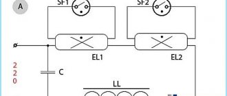
Option for connecting two fluorescent lamps through one choke: 1 – filter capacitor; 2 – choke, power equal to the power of two light devices; 3, 4 – lamps; 5,6 – starting starters; L – phase power line; N – zero line
Based on the same schematics, a solution is implemented with the connection of two fluorescent lamps, one choke and two starters. True, in this case it is necessary to select a choke based on power, based on the total power of gas lamps.
The throttle circuit option can be modified to eliminate the gating defect. It quite often occurs on lamps with electromagnetic electronic ballasts.
The modification is accompanied by the addition of a diode bridge to the circuit, which is switched on after the inductor.
What benefits do you receive as a client?
Güntner sets the highest standards for the production of specialized heat exchangers, while maintaining the objectivity and transparency of these standards. That's why we participate in the Eurovent programme. The purpose of the program is to promote fair competition and provide equal testing conditions for products on the market. To achieve this, manufacturers' specifications are studied by independent laboratories. As part of this check, devices from the relevant manufacturer are selected at random.
The HE program (Heat Exchangers for Refrigeration) for heat exchangers used in refrigeration and air conditioning systems has been in operation since 2001. Güntner has been a constant and successful participant in the program since its inception; All series included in the program are certified without exception for 15 years!
The Eurovent certification program includes DX direct expansion evaporators and condensers designed for R404A, R134a, R507A, R407A, R407C or R407F refrigerants.
The Evrovent program certifies liquid air coolers, ammonia evaporators and condensers, CO2 evaporators and condensers, 60 Hz units and centrifugal fans. Certification of a separate product group, including CO2 air coolers and DX evaporators, is planned for 2022.
Using certified devices gives you significant material benefits:
An important component of certification is the classification of devices according to energy efficiency classes. This classification provides information about the expected energy consumption of the selected device
This means that you can clearly calculate operating costs. Independently verified specifications simplify device design. You can design precisely to the operating point; There is no need to provide a safety margin. Thanks to certified specifications, devices are easier to compare with each other. This ensures fair competition in real conditions. The principle of universal certification ensures that manufacturers cannot differentiate themselves with individual “bestsellers”: Series are fully certified, thus leaving no “loopholes” for individual models. Validated and therefore reliable technical data increases investment security and guarantees planning safety and operational reliability in terms of performance and energy efficiency of the entire system. Operating costs can be calculated at the very beginning. Certified appliances save real money: “We recommend that every consumer calculate the energy costs for a current or future construction project to avoid insufficient power. Several years ago, uncertified devices showed a power deficiency of up to 35% in serial testing. Thus, you can expect a performance reduction of 15 - 20% below the calculated one. Certified devices have a comparatively shorter payback period, usually less than 2 years,” says Peter Roth, Eurovent specialist at Güntner. Eurovent certification is a prerequisite for receiving subsidies under some funding programs. The certification applies to all standard devices. Thanks to its modular design, Güntner's new product line-up includes an even wider range of certified units, which are subject to financing discussions.
Connection to electronic modules
The connection options for fluorescent lamps on electronic modules are somewhat different. Each electronic ballast has input terminals for supplying mains voltage and output terminals for load.
Depending on the electronic ballast configuration, one or more lamps are connected. As a rule, on the body of a device of any power, designed to connect the corresponding number of lamps, there is a circuit diagram for switching on.
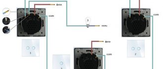
The procedure for connecting fluorescent lamps to a starting and control device operating on semiconductor elements: 1 – interface for network and grounding; 2 – interface for lamps; 3.4 - lamps; L – phase power line; N – zero line; 1…6 — interface contacts
The diagram above, for example, provides for powering a maximum of two fluorescent lamps, since the diagram uses a two-lamp ballast model.
The two interfaces of the device are designed as follows: one for connecting the mains voltage and ground wire, the second for connecting lamps. This option is also one of a series of simple solutions.
A similar device, but designed to work with four lamps, is distinguished by the presence of an increased number of terminals on the load connection interface. The network interface and ground connection line remain unchanged.
Connection wiring according to the four-lamp version. An electronic semiconductor electronic ballast is also used as a triggering and control device. In diagram 1...10 - contacts of the start-up and control device interface
However, along with simple devices - one-, two-, four-lamp - there are ballast structures, the schematics of which provide for the use of the function of adjusting the glow of fluorescent lamps using.
These are the so-called controlled models of regulators. We recommend that you familiarize yourself in more detail with the operating principle of the lighting power regulator.
How do such devices differ from the devices already discussed? The fact that, in addition to the network and load ones, they are also equipped with an interface for connecting control voltage, the level of which is usually 1-10 volts DC.
Four-lamp configuration with the ability to smoothly adjust the brightness: 1 – mode switch; 2 – control voltage supply contacts; 3 – grounding contact; 4, 5, 6, 7 – fluorescent lamps; L – phase power line; N – zero line; 1…20—starter and control device interface contacts
Thus, the variety of configurations of electronic ballast modules allows you to organize lighting systems of different levels. This refers not only to the level of power and area coverage, but also to the level of control.
How to open the website ghf.ru?
The most common reasons why the ghf.ru website does not open may be as follows:
- The site is blocked by your ISP. To open the site, use VPN services.
- Viruses overwrote the hosts file. Open the file C:\Windows\System32\drivers\etc\hosts (Windows) or /ets/hosts (Unix) and erase the lines associated with the ghf.ru website.
- Your antivirus or firewall is blocking access to this site. Try turning them off.
- The AdBlock extension (or another similar one) blocks the content of the site. Disable the plugin for this site.
- Sometimes the problem with a website being unavailable is a browser error. Try opening the ghf.ru website in another browser, for example: Firefox, Chrome, Opera, Internet Explorer, Safari.
- Problems with DNS with your provider.
- Problems on the provider's side.
Conclusions and useful video on the topic
The video material, based on the practice of an electrician, tells and shows which of the two devices should be recognized by the end user as better and more practical.
This story once again confirms that simple solutions look reliable and durable:
Meanwhile, electronic ballasts continue to be improved. New models of such devices periodically appear on the market. Electronic designs are also not without drawbacks, but compared to electromagnetic options, they clearly show better technical and operational qualities.
Do you understand the principles of operation and connection diagrams of electronic ballasts and want to supplement the above material with personal observations? Or would you like to share useful recommendations on the nuances of repairing, replacing or choosing a ballast? Please write your comments on this entry in the block below.
Disadvantages of electronic ballasts:
There are quite a lot of advantages, but there is still no clear opinion about reliability. It is possible that due to the low quality of electricity received from power plants in Russia, they fail more often.
Therefore, to this day, installers prefer chokes, which cost 3 times less. But there are just as many positive reviews. In addition, electronic devices are much more expensive compared to electronic ballasts. This drawback largely influences the choice.
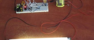
If you have the time and desire to see the tests visually, I suggest you watch a short 3-minute video:
In any case, it’s up to you to decide what to prefer. Personally, I recommend that you spend a little more and choose warm start electronic ballasts from reputable manufacturers. These costs will pay for themselves.
And if you are planning to calculate lighting for your house or apartment, our article can help you - a simple method for calculating lighting.
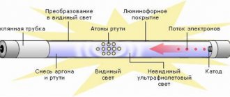
Principle of operation
Let's look at what a fluorescent lamp is and how it works. It is a glass tube that begins to work due to a discharge that ignites the gases inside its shell. A cathode and anode are installed at both ends, and it is between them that the discharge occurs, which causes the starting ignition.
Mercury vapor, which is placed in a glass case, when discharged, begins to emit a special invisible light, which activates the work of the phosphor and other additional elements. It is they who begin to emit the light that we need.
Operating principle of the lamp
Due to the different properties of the phosphor, such a lamp emits a wide range of different colors.
Circuits with starter
The very first circuits with starters and chokes appeared. These were (in some versions they are) two separate devices, each of which had its own socket. There are also two capacitors in the circuit: one is connected in parallel (to stabilize the voltage), the second is located in the starter housing (increases the duration of the starting pulse). This whole “economy” is called electromagnetic ballast. The diagram of a fluorescent lamp with a starter and choke is shown in the photo below.
Connection diagram for fluorescent lamps with starter
Here's how it works:
- When the power is turned on, current flows through the inductor and enters the first tungsten coil. Next, through the starter it enters the second spiral and leaves through the neutral conductor. At the same time, the tungsten filaments gradually heat up, as do the starter contacts.
- The starter consists of two contacts. One is fixed, the second is movable bimetallic. In normal condition they are open. When current passes, the bimetallic contact heats up, which causes it to bend. By bending, it connects to a fixed contact.
- As soon as the contacts are connected, the current in the circuit instantly increases (2-3 times). It is limited only by the throttle.
- Due to the sharp jump, the electrodes heat up very quickly.
- The starter bimetallic plate cools down and breaks contact.
- At the moment the contact breaks, a sharp voltage surge occurs across the inductor (self-induction). This voltage is enough for electrons to break through the argon medium. Ignition occurs and the lamp gradually enters operating mode. It occurs after all the mercury has evaporated.
The operating voltage in the lamp is lower than the mains voltage for which the starter is designed. That's why it doesn't work after ignition. When the lamp is working, its contacts are open and it does not participate in its operation in any way.
This circuit is also called electromagnetic ballast (EMB), and the operating diagram of an electromagnetic ballast is called EMBRA. This device is often simply called a choke.
One of the EmPRA
There are quite a few disadvantages to this fluorescent lamp connection scheme:
- pulsating light, which negatively affects the eyes and they quickly get tired;
- noise during start-up and operation;
- inability to start at low temperatures;
- long start - about 1-3 seconds pass from the moment of switching on.
Two tubes and two chokes
In luminaires with two fluorescent lamps, two sets are connected in series:
- the phase wire is supplied to the inductor input;
- from the throttle output it goes to one contact of lamp 1, from the second contact it goes to starter 1;
- from starter 1 it goes to the second pair of contacts of the same lamp 1, and the free contact is connected to the neutral power wire (N);
The second tube is also connected: first the choke, from it to one contact of lamp 2, the second contact of the same group goes to the second starter, the starter output is connected to the second pair of contacts of the lighting device 2 and the free contact is connected to the neutral input wire.
Connection diagram for two fluorescent lamps
The same connection diagram for a two-lamp fluorescent lamp is demonstrated in the video. This might make it easier to deal with the wires.
https://youtube.com/watch?v=8fF5KQk4L2k
Connection diagram for two lamps from one choke (with two starters)
Almost the most expensive in this scheme are the chokes. You can save money and make a two-lamp lamp with one choke. How - watch the video.
Summary
A brief analysis shows that most of the advantages of electronic ballasts on the street either cease to be an advantage or are not important, and the disadvantages are fundamental. Therefore, lamps with electronic ballasts are unpopular in America, in Europe, and unpopular here. Their share in the total number of street lamps is less than 1%, and this is not just so.
At the same time, in interior lighting the situation is radically opposite; the use of electronic ballasts is justified, expedient, and cost-effective.
In street lighting, it is recommended to use either luminaires with traditional electromagnetic ballasts, or, for lighting control tasks, electric magnetic ballasts with switching windings.
What is an RCD in electrical engineering?
Despite the fact that these days electrical wiring is maximally protected from contact with people and sad consequences, there is no escape from leaks. This is where the RCD will become an indispensable assistant. The device will react with lightning speed to an increased current value at the leakage point and cut off the power supply.
RCD is one of the main “cogs” in the protective automation of current electrical networks. The device switches electrical circuits and protects them from currents that flow along conductive paths that are undesirable under standard conditions. This will increase the chances that your home or business will be protected from fires and no one will be harmed by an electric shock.
Note that this device has the function of turning on or off electrical circuits. In other words, it can switch them. Accordingly, the device is a switching one.
Why install an RCD?
Many consumers have heard about the existence of such a miracle device as an RCD, but not everyone knows what it is for. You can understand the general principles of operation of the unit even without deep knowledge of electricity. Until recently, RCDs were not used in residential buildings. But nowadays everything has changed, and now devices are increasingly found in apartments, so it’s worth learning more about them.
As already mentioned, RCDs are installed in order to prevent current leaks that lead to wiring fires and fires. In addition, the RCD will protect you from electric shock, which can lead to significant health problems or, God forbid, death when coming into contact with bare wires and conductive sections of electrical equipment.
Operating principle of RCD
The operation of the device is based on recording the leakage current to the ground and disconnecting the power grid in the event of such an emergency. The device detects the presence of a leak only by the difference between the currents: those that came out of the device and those that returned back.
If everything is in order with the electrical network, then the currents are identical in magnitude, but differ in direction. As soon as a leak appears - for example, you touched a wire that is not 100% insulated - part of the current goes “to the ground” through another circuit (in this case, through the human body). As a result, the current returning to the RCD through the neutral will be less than that leaving it.
The same thing happens if the insulation in one of the electrical appliances is damaged. Then the housing or other part is under tension. By touching them, a person creates another circuit “to the ground.” In this case, part of the current will move along it, that is, the balance will be destroyed.