| This article or section needs revision. Please improve the article in accordance with the rules for writing articles. |
This term has other meanings, see Frequency (meanings).
| Frequency | |
| ν = nt {\displaystyle \nu ={\frac {n}{t))} | |
| Dimension | T −1 |
| Units | |
Frequency
- a physical quantity, a characteristic of a periodic process, equal to the number of repetitions or occurrences of events (processes) per unit of time.
It is calculated as the ratio of the number of repetitions or occurrence of events (processes) to the period of time during which they occurred[1]. Standard notations in formulas are the letter of the Latin alphabet “eff” f
,
F
or the letter of the Greek alphabet “nu” (ν).
The unit of frequency in the International System of Units (SI) is the hertz (Russian designation: Hz; international: Hz), named after the German physicist Heinrich Hertz.
The frequency is inversely proportional to the oscillation period: ν
= 1/
T
.
| Frequency | 1 MHz (10−3 Hz) | 1 Hz (100 Hz) | 1 kHz (103 Hz) | 1 MHz (106 Hz) | 1 GHz (109 Hz) | 1 THz (1012 Hz) |
| Period | 1 ks (103 s) | 1 s (100 s) | 1 ms (10−3 s) | 1 µs (10−6 s) | 1 ns (10−9 s) | 1 ps (10−12 s) |
Frequency, like time, is one of the most accurately measured physical quantities: up to a relative accuracy of 10−17[2].
Periodic processes are known in nature with frequencies from ~10−16 Hz (the frequency of the Sun's revolution around the center of the Galaxy) to ~1035 Hz (the frequency of field oscillations characteristic of the most high-energy cosmic rays).
In quantum mechanics, the frequency of oscillations of the wave function of a quantum mechanical state has the physical meaning of the energy of this state, and therefore the system of units is often chosen in such a way that frequency and energy are expressed in the same units (in other words, the conversion factor between frequency and energy is a constant Planck in Formula E
=
h
ν — is chosen equal to 1).
The human eye is sensitive to electromagnetic waves with frequencies from 4⋅1014 to 8⋅1014 Hz (visible light); The frequency of vibration determines the color of the observed light. The human auditory analyzer perceives acoustic waves with frequencies from 20 Hz to 20 kHz. Different animals have different frequency ranges of sensitivity to optical and acoustic vibrations.
The ratios of the frequencies of sound vibrations are expressed using musical intervals, such as octave, fifth, third, etc. An interval of one octave between the frequencies of sounds means that these frequencies differ by a factor of 2, an interval of a perfect fifth means a frequency ratio of 3⁄2. In addition, to describe frequency intervals, a decade is used - the interval between frequencies that differ by a factor of 10. Thus, the range of human sound sensitivity is 3 decades (20 Hz - 20,000 Hz). To measure the ratio of very close audio frequencies, units such as the cent (frequency ratio of 21/1200) and millioctave (frequency ratio of 21/1000) are used.
§ 51. Reception and transmission of alternating electric current. Transformer -
Questions. 1. What electric current is called alternating?
With the help of what simple experience can it be obtained? An alternating current is a current that periodically changes over time in magnitude and direction. Alternating current can be obtained using an induction coil, a galvanometer and a magnet. By periodically moving the magnet up and down inside the coil, you will notice that the galvanometer plate deviates in one direction or the other.
2. Where is alternating electric current used?
Alternating electric current is used in everyday life and industry.
3. On what phenomenon is the operation of the currently most common alternating current generators based?
The operation of alternating current generators is based on the phenomenon of electromagnetic induction.
4. Tell us about the structure and operating principle of an industrial generator.
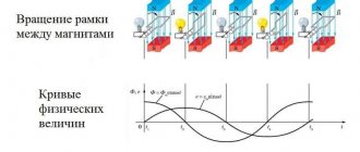
An industrial alternating current generator consists of a stator and a rotor. The stator is fixed, and the rotor rotates. The rotor and stator are wrapped in a special way with copper wire. The rotor is supplied with a constant electric current and is thus an electromagnet. When the rotor rotates, the magnetic field it creates also rotates. In this case, an alternating magnetic flux penetrates the stator winding and an alternating electric current arises in it.
5. What drives the generator rotor at a thermal power plant? at a hydroelectric power station?
Steam and water turbine.
6. Why are multi-pole rotors used in hydrogen generators?
To create a current of standard frequency, because The rotation speed of water turbines is low.
7. What is the standard frequency of industrial current used in Russia and many other countries?
The standard frequency in Russia is 50 Hz, in the USA - 60 Hz.
8. By what physical law can energy losses in power lines be determined?
According to the Joule-Lenz law: Q= I 2 Rt, where Q is the energy spent on heating the wires, I is the effective value of the alternating current in the circuit, R is the resistance of the wires, t is time.
9. What should be done to reduce electricity losses during transmission?
From the Joule-Lenz law it follows that for this it is necessary to reduce the circuit resistance R and the current I.
10. Why, when the current strength decreases, is its voltage increased by the same amount before being fed into the power line?
In order not to reduce the current power P= UI. Transmitting low-power current over long distances is not economically viable (it is necessary to build expensive power lines, stations and substations, and as a result, not all consumers will be able to use electricity).
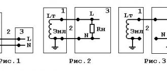
11. Tell us about the structure, principle of operation and application of transformers.
How did the electrification of Russia begin?
The majority of the adult population of Russia and other countries of the former USSR today fortunately know that large-scale electrification of the country is associated with the implementation of the State Electrification of Russia (GoElRo) plan adopted in 1920.
In fairness, it should be noted that the development of this plan dates back to the time before the First World War, which, in fact, then prevented its adoption. This article will focus on the period preceding it, when electricity was just entering the everyday life of the population of large cities, and was an admirable curiosity, a symbol of omnipotent Progress.
It seems that many readers will be surprised, but even today in the old houses of Zamoskvorechye you can find working electrical wiring laid at the turn of the 80-90s of the 19th century during the first electrification of Moscow. However, the events associated with this action were also not the first milestone on the path of the victorious march through the territory of the then Russian Empire of the new driving force. When determining the time of the beginning of the existence of any phenomenon, difficulties and discrepancies always arise, however, we will designate 1879 as the beginning of the era of electricity in Russia.
So, it was this year that the Liteiny Bridge in St. Petersburg was illuminated with electric light, becoming the first bridge in the world illuminated using electricity. Connected with this event is a curious story about how the St. Petersburg City Government sold the monopoly on street lighting to private companies that lit them with oil and gas lamps. The Liteiny Bridge, as it was built after the conclusion of this agreement, was not subject to the agreement; as a result, the electrification of the Russian capital and the empire as a whole began with the bridge. 1. Liteiny Bridge. Start of construction: August 30, 1875. Opening: September 30, 1879.
2. View of Liteiny Bridge from Kutuzov Embankment, June 2007.
A year earlier, in 1878, engineer Borodin carried out the electrification of the turning shop of the Kyiv railway workshops, during which the workshop was illuminated by four electric arc lamps. We know about this fact, but it was not chosen as the initial date due to its narrow departmental significance and the inaccessibility of viewing this miracle to the general public.
The next milestone on the path to introducing new products into everyday life was January 30, 1880, when the electrical engineering department of the Russian Technical Society was founded, designed to oversee the problems of electrification in Russia. In the same year, work began on lighting the streets of Moscow and St. Petersburg, but their volume can be considered extremely insignificant - a couple of hundred lamps for the two capitals. Also in the same year, in Kyiv, the workshops of the Dnieper Shipping Company were illuminated using Yablochkov lamps.
At this stage of electrification, all consumers of electricity (which were exclusively lighting devices) used direct current, and there were certain problems with transmitting electricity over significant distances. As a result, the source of electricity was located in close proximity to the consumer. So, for example, in the case of the Kyiv railway workshops, each of the four lamps had its own electromagnetic Gram machine.
Exactly two years after the coronation of Emperor Alexander III in St. Petersburg, celebrations on a similar occasion in Moscow on May 15, 1883 were marked by grandiose illumination of the Kremlin. To implement this project, a special power station was built on Sofia Embankment.
3. “Illumination of the Kremlin”, 1883, artist Alexey Petrovich Bogolyubov
In the same year, but already in the capital of the Empire, it illuminates the central street of the city, and a little later the Winter Palace is electrified. According to some data, it is precisely for the implementation of these measures that perhaps the first, more or less large power plant in Russia, with a capacity of 35 kW, is being built. Among other things, this power plant is notable for the fact that it was located on a barge moored to the Moika embankment not far from the Police Bridge. 4. Winter Palace, 1752
5. Winter Palace from Dvortsovy Proezd, 2012
There are no further references to any major events related to electricity for a number of years, until in 1886 it becomes known about the lighting of the Chateau de Fleurs park in Kiev (now Dynamo Stadium) with electricity.
On July 31, 1887, the Electric Lighting Society, founded by Karl Fedorovich Siemens (who by that time had accepted Russian citizenship and became a merchant of the first guild), decided to begin work aimed at the practical electrification of Moscow. The implementation of these ambitious plans began with the installation of electric lighting for the Postnikovsky passage on Tverskaya, now the Theater named after. Ermolova.
In general, the “Electric Lighting Society of 1886”, whose charter was approved on July 4, 1886 by the highest Decree of Emperor Alexander III, played a huge role in the initial electrification of Russia. After the revolution of 1917, the nationalized capacities of this enterprise were combined into a single energy system, on the basis of which, in particular, JSC MOSENERGO in Moscow now operates.
On February 3, 1888, a land lease agreement was concluded in Moscow for the construction of the first central city power plant. The power plant, called Georgievskaya (located on the corner of Bolshaya Dmitrovka and Georgievsky Lane) generated direct current and supplied electricity to consumers (including private homeowners) within a radius of one and a half miles. All cables were laid in brick channels. 6. Georgievskaya power station, Moscow, 1902
At this time, in addition to the Central one, a number of smaller power plants were operating in Moscow - Gorodskaya, which illuminated the Stone Bridge and the square of the Cathedral of Christ the Savior, Universitetskaya, Imperial Theaters, Dvortsovaya (illuminated the Kremlin), at the Yaroslavl and Brest stations. Things were approximately the same in the other two largest cities of the empire - St. Petersburg and Kyiv. The use of direct current limited the length of power cables, forcing the use of small local power plants. 7. Machine room. Raushskaya embankment power plant, Moscow, 1911
On July 3, 1892, the first electric tram in Russia was launched in Kyiv; the line had a length of one and a half kilometers. The power of the power supply plant was 30 kW. 8. The first electric tram in the Russian Empire, 1892
The year 1895 was marked by the commissioning of Russia's first hydroelectric power station on the Bolshaya Okhta River in St. Petersburg, with a rather large capacity for those times - 300 kW. In the same year, the Administration of the Vladikavkaz Railway built and put into operation the White Coal hydroelectric station on the Podkumok River, between Kislovodsk and Essentuki, which provided electricity for lighting resorts. 9. HPP “White Coal” (Pyatigorsk HPP)
The electrification of Russia at that time was not of a planned, centralized nature, so the milestones given are not a complete list of all measures to electrify the country. The houses of wealthy homeowners installed their own sources of electricity, sometimes quite powerful, and the same was observed in agriculture and estate land ownership, but such events rarely made it to the pages of newspapers, and accordingly we know little about them.
An important event during the period of the beginning of the electrification of the country was the construction and commissioning of a power station on Raushskaya embankment, the first truly large power station in Russia, and, moreover, generating three-phase alternating current. This made it possible to transmit power over long distances using higher voltage. On April 28, 1897, the installation of electrical equipment began, and in November of the same year the power plant was launched. At that time, the power of this steam turbine power plant was 1470 kW (already during the First World War, in 1915, the second stage of this power plant with a capacity of 21 MW was launched).
The oldest household lighting wiring that has survived to this day in Moscow was apparently powered precisely from this power plant. Consumers received alternating current with a frequency of 50 Hz. The household power supply voltage was 127 V.
Over time, a situation arose when electric trams, which appeared in Moscow at the beginning of the 20th century, began to consume most of the electricity generated by the Raush power plant. To relieve it, in 1907, a power plant was built near the Maly-Kamenny Bridge to power the tram network. Its power at the time of launch was 6000 kW. 10. The first power plant in Kursk. Photo from 1901
Some dates to some extent characterize the spread of a new energy source across the country:
1901 - the first power plants were launched in Kursk and Yaroslavl. 1908 - the first power plant in Chita came into operation. 1912 – commissioning of a power plant in Vladivostok. 1912-14 – construction and launch of the world’s largest peat thermal power plant “Electroperedacha” near the city of Bogorodsk (now Noginsk). 1915 is the date from which the Moscow Electric Lamp Plant begins its history. And so on…
The result of the pre-war development of the Russian electric power industry was the achievement of a total installed capacity of electricity sources of 1,100 MW and a production of 1,900,000 MWh per year (data from 1913). As for hydroelectric power plants, by 1917 in Russia they had a total capacity of about 19 MW, and the most powerful hydroelectric power station in the empire was the Hindu Kush - 1.35 MW.
11. Turbine room of the Hindu Kush hydroelectric power station with a capacity of 1.35 MW on the river. Murghab (Turkmenistan).
Its construction was completed in 1909 (photo of 1911, by Prokudin-Gorsky)
Frequency
About frequency in the Unified Energy System of Russia
The frequency of electric current is one of the indicators of the quality of electrical energy and the most important parameter of the power system mode. The frequency value shows the current state of the balance of generated and consumed active power in the power system. The operation of the Unified Energy System of Russia is planned for a nominal frequency of 50 hertz (Hz). The continuity of electricity production, the inability to store energy on an industrial scale and the constant change in consumption volumes require equally continuous monitoring of the correspondence of the amount of electricity produced and consumed. An indicator characterizing the accuracy of this correspondence is frequency.
When operating in the UES mode, fluctuations in the power balance constantly occur, mainly due to instability of consumption, and also (much less frequently) when generating equipment, power lines and other elements of the power system are turned off. The indicated power balance deviations lead to frequency deviations from the nominal level.
An increased frequency level in the power system relative to the nominal one means an excess of generated active power relative to the consumption of the power system, and vice versa, a reduced frequency level means a lack of generated active power relative to consumption.
Thus, regulation of the power system mode by frequency consists in constantly maintaining the planned power balance by manually or automatically (and more often, both at the same time) changing the load of power plant generators so that the frequency always remains close to the nominal one. In emergency situations, when the reserves of the generating equipment of power plants are not enough, limiting the load of consumers can be applied to restore the permissible frequency level.
Regulation of the frequency of electric current in the Unified Energy System of Russia is carried out in accordance with the requirements established by the Standard of JSC SO UES STO 59012820.27.100.003-2012 “Regulation of frequency and active power flows in the Unified Energy System of Russia. Norms and requirements" (as amended on January 31, 2017) and the national standard of the Russian Federation GOST R 55890-2013 "Unified energy system and isolated operating energy systems. Operational dispatch control. Regulation of frequency and active power flows. Norms and Requirements” (hereinafter – Standards).
According to these Standards, in the first synchronous zone of the UES of Russia, it must be ensured that frequency values averaged over a 20-second time interval are maintained within the limits of (50.00 ± 0.05) Hz, while it is permissible for frequency values to be within (50.0 ± 0.2 ) Hz with frequency restoration to the level of (50.00±0.05) Hz in no more than 15 minutes. High requirements for maintaining frequency are due to the need to coordinate frequency deviations with the planned capacity reserves of controlled sections of the UES under normal conditions. For the UES of Russia, which is characterized by extensive intersystem connections included in controlled sections, more stringent standards for maintaining frequency and, accordingly, power balance, make it possible to make maximum use of the throughput of these connections.
All rotating mechanisms in synchronously operating parts of the power system (turbines, generators, engines, etc.) have rated design speeds proportional to the rated frequency in the network. It is known that the nominal operating mode of all rotating mechanisms is the most effective in terms of their efficiency, reliability and durability. Deviation from the nominal speed leads to undesirable effects in the operation of equipment of power plants and consumers (the occurrence of increased vibrations, wear, etc.), a decrease in their efficiency and reliability. For different equipment there are maximum permissible frequency deviations from the nominal. Maintaining the frequency at a level close to the nominal ensures maximum efficiency of operation of power equipment and maximum margin of reliability of power systems.
Metrological aspects[ | ]
To measure frequency, different types of frequency meters are used, including: to measure the frequency of pulses - electronic counting and capacitor ones, to determine the frequencies of spectral components - resonant and heterodyne frequency meters, as well as spectrum analyzers. To reproduce the frequency with a given accuracy, various measures are used - frequency standards (high accuracy), frequency synthesizers, signal generators, etc. The frequencies are compared with a frequency comparator or using an oscilloscope using Lissajous figures.
Standards[ | ]
National frequency standards are used to verify frequency measuring instruments. In Russia, national frequency standards include:
- The state primary standard of units of time, frequency and national time scale GET 1-98 is located at VNIIFTRI.
- The secondary standard of the unit of time and frequency VET 1-10-82
is located in SNIIM (Novosibirsk).
Calculations[ | ]
Calculating the frequency of a recurring event is done by taking into account the number of occurrences of that event during a given period of time. The resulting amount is divided by the duration of the corresponding time period. For example, if 71 homogeneous events occurred within 15 seconds, then the frequency will be
ν = 71 15 s ≈ 4 , 7 Hz {\displaystyle \nu ={\frac {71}{15\,{\mbox{s}}}}\approx 4{,}7\,{\mbox{Hz} }}
If the obtained number of samples is small, then a more accurate technique is to measure the time interval for a given number of occurrences of the event in question, rather than finding the number of events within a given period of time[8]. Using the latter method introduces a random error between zero and first readings, averaging half a reading; this can lead to an average error in the calculated frequency Δν = 1/(2 Tm
), or the relative error Δ
ν
/
ν
= 1/(2
vTm
), where
Tm
is the time interval and ν is the measured frequency.
The error decreases as the frequency increases, so this problem is most significant at low frequencies, where the number of samples N
is small.
Measurement methods[ | ]
Stroboscopic method[ | ]
The use of a special device - a strobe - is one of the historically early methods of measuring the rotational speed or vibration of various objects. The measurement process uses a stroboscopic light source (usually a bright lamp that periodically produces short flashes of light), the frequency of which is adjusted using a pre-calibrated timing circuit. A light source is directed at a rotating object, and then the frequency of flashes is gradually changed. When the frequency of the flashes is equalized with the frequency of rotation or vibration of the object, the latter has time to complete a complete oscillatory cycle and return to its original position in the interval between two flashes, so that when illuminated by a strobe lamp, this object will appear motionless. This method, however, has a drawback: if the object’s rotation frequency ( x
) is not equal to the strobe frequency (
y
), but is proportional to it with an integer coefficient (2
x
, 3
x
, etc.), then the object will still look motionless when illuminated.
The stroboscopic method is also used to fine-tune the rotational speed (oscillations). In this case, the frequency of the flashes is fixed, and the frequency of the periodic movement of the object changes until it begins to appear motionless.
Beat method[ | ]
Close to the stroboscopic method is the beat method. It is based on the fact that when mixing oscillations of two frequencies (reference ν
and measured
ν'1 ) in a nonlinear circuit, a difference frequency Δν = |
ν
−
ν'1|, called the beat frequency (with linear addition of oscillations, this frequency is the frequency of the envelope of the total oscillation).
The method is applicable when it is more preferable to measure low-frequency oscillations with a frequency Δ f
. In radio engineering, this method is also known as the heterodyne frequency measurement method. In particular, the beat method is used to finely tune musical instruments. In this case, sound vibrations of a fixed frequency (for example, from a tuning fork), heard simultaneously with the sound of the instrument being tuned, create a periodic increase and decrease in the total sound. When fine-tuning the instrument, the frequency of these beats tends to zero.
Application of a frequency meter[ | ]
High frequencies are usually measured using a frequency meter. This is an electronic instrument that evaluates the frequency of a specific repeating signal and displays the result on a digital display or analogue indicator. Discrete logic elements of a digital frequency meter allow you to take into account the number of periods of signal oscillations within a given period of time, counted by a reference quartz clock. Periodic processes that are not electrical in nature (such as, for example, rotation of an axis, mechanical vibrations or sound waves) can be converted into a periodic electrical signal using a measuring transducer and, in this form, supplied to the input of a frequency meter. Currently, devices of this type are capable of covering a range of up to 100 Hz; this figure represents a practical ceiling for direct counting methods. Higher frequencies are measured using indirect methods.
Indirect measurement methods[ | ]
Outside the range available to frequency meters, the frequencies of electromagnetic signals are often estimated indirectly, using local oscillators (that is, frequency converters). A reference signal of a predetermined frequency is combined in a nonlinear mixer (such as a diode) with the signal whose frequency needs to be set; the result is a heterodyne signal, or - alternatively - beats generated by the frequency differences of the two original signals. If the latter are sufficiently close to each other in their frequency characteristics, then the heterodyne signal turns out to be small enough that it can be measured with the same frequency meter. Accordingly, as a result of this process, only the difference between the unknown frequency and the reference frequency is estimated, which should be determined by other methods. Multiple mixing stages can be used to cover even higher frequencies. Research is currently underway to extend this method towards infrared and visible light frequencies (so-called optical heterodyne detection).
Mains voltage parameters in Russia [ | ]
Electricity producers generate alternating current at industrial frequency (50 Hz in Russia). In the vast majority of cases, three-phase current is transmitted along power lines, increased to high and ultra-high electrical voltage using transformer substations that are located next to power plants.
According to the interstate standard GOST 29322-2014 (IEC 60038:2009), the mains voltage should be 230 V ±10% at a frequency of 50 ±0.2 Hz [1] (phase-to-phase voltage 400 V, phase-neutral voltage 230 V, four-wire connection circuit "star"), note "a)" of the standard states: "However, 220/380 V and 240/415 V systems are still in use."
(three phase wires and one neutral (neutral) wire) are supplied to residential buildings (rural streets).
power lines (overhead or cable power lines) with a phase-to-phase voltage of 400 Volts. Input machines and electricity consumption meters are usually three-phase. A phase wire, a neutral wire and, possibly, a protective grounding or grounding wire are supplied to a single-phase socket; the electrical voltage between the “phase” and “zero” is 230 Volts.
The rules for the design of electrical installations (PUE-7) continue to include the value 220
Rated voltages of household networks (low voltage): Russia (USSR, CIS) [ | ]
Until 1926, technical regulation of general-purpose electrical networks was carried out by the Electrical Engineering Department of the IRTS, which only issued rules for safe operation. When examining the networks of the RSFSR before creating the GOELRO plan, it was found that at that time almost all possible voltages of electric currents of all types were used. Beginning in 1926, the standardization of electrical networks passed to the Standardization Committee under the Council of Labor and Defense (Gosstandart), which issued standards for the rated voltages of networks and equipment used. Since 1992, the Interstate Council for Standardization, Metrology and Certification has been issuing standards for electrical networks of countries included in the Unified Energy System.
Industrial frequency - current
Industrial current frequency (50 Hz) is the most unfavorable for humans. As the frequency increases, the value of the non-releasing current changes slightly. With decreasing frequency, the value of the non-releasing current increases and at a frequency equal to zero (direct current), it becomes approximately 3 times larger. The values of the fibrillation current at frequencies of 50 - 100 Hz are equal; with an increase in frequency to 200 Hz, the current increases approximately 2 times, and at a frequency of 400 Hz - almost 4 times. [1] At an industrial frequency of the current in the coil of 50 Hz, the thickness of the sheets is usually 0 35 - 0 5 mm. At higher frequencies, the thickness of the sheets decreases to 0 02 - 0 05 mm. 0 5 - 4 5% silicon (Si) is added to the magnetic circuit material; such an additive significantly increases the electrical resistivity of the material and has little effect on its magnetic properties. [2]
At an industrial frequency of current in the coil of 50 Hz, the thickness of the sheets is usually 0 35 - 0 5 mm. At higher frequencies, the thickness of the sheets decreases to 0 02 - 0 05 mm. [3]
At industrial frequency current, the hopper and tray 6 located in it make 100 oscillations per second. With a change in voltage, the traction force of the electromagnets changes, and, consequently, the amount of movement of the armature and spring. [5]
At an industrial frequency of current in the coil of 50 Hz, the thickness of the sheets is usually 0 35 - 0 5 mm. At higher frequencies, the thickness of the sheets decreases to 0 02 - 0 05 mm. 0 5 - 4 5% silicon (Si) is added to the magnetic circuit material; such an additive significantly increases the electrical resistivity of the material and has little effect on its magnetic properties. [6]
The operation of protective devices in case of damage is mainly determined by the periodic components of the industrial frequency of currents / p and voltages t / p acting on the relay, and the phase shifts fr between them. [eleven]
The operation of protective devices during a short circuit is in most cases determined by the periodic components of the industrial frequency of currents / p and voltages UP supplied to the relay, as well as the phase shifts fr between them. Below, for the purpose of simplification, we consider the relationships that characterize them for an unloaded line with one-sided supply (Fig. 1.24) at the initial moment of damage. Two-way power supply, loads and other additional factors are taken into account only for some typical cases. [13]
The operation of protective devices during a short circuit is in most cases determined by the periodic components of the industrial frequency currents / p and voltages Up supplied to the relay, as well as the phase shifts pp between them. Below, for the purpose of simplification, we consider the relationships that characterize them for an unloaded line with one-sided supply (Fig. 1.24) at the initial moment of damage. Two-way power supply, loads and other additional factors are taken into account only for some typical cases. [15]
Source
Great Encyclopedia of Oil and Gas
At industrial frequency current, the hopper and tray 6 located in it make 100 oscillations per second. With a change in voltage, the traction force of the electromagnets changes, and, consequently, the amount of movement of the armature and spring. [5]
The operation of protective devices in case of damage is mainly determined by the periodic components of the industrial frequency of currents / p and voltages t / p acting on the relay, and the phase shifts fr between them. [eleven]
The operation of protective devices during a short circuit is in most cases determined by the periodic components of the industrial frequency of currents / p and voltages UP supplied to the relay, as well as the phase shifts fr between them. Below, for the purpose of simplification, we consider the relationships that characterize them for an unloaded line with one-sided supply (Fig. 1.24) at the initial moment of damage. Two-way power supply, loads and other additional factors are taken into account only for some typical cases. [13]
The operation of protective devices during a short circuit is in most cases determined by the periodic components of the industrial frequency currents / p and voltages Up supplied to the relay, as well as the phase shifts pp between them. Below, for the purpose of simplification, we consider the relationships that characterize them for an unloaded line with one-sided supply (Fig. 1.24) at the initial moment of damage. Two-way power supply, loads and other additional factors are taken into account only for some typical cases. [15]
Source
Cyclic frequency[ | ]
Main article: Angular frequency
In the theory of electromagnetism, theoretical physics, as well as in some applied electrical and radio engineering calculations, it is convenient to use an additional quantity - cyclic (circular, radial, angular) frequency (usually denoted ω). Angular frequency (synonyms: radial frequency, cyclic frequency, circular frequency) is a scalar physical quantity. In the case of rotational motion, the angular frequency is equal to the magnitude of the angular velocity vector. In the SI and GHS systems, the angular frequency is expressed in radians per second, its dimension is the inverse of the dimension of time (radians are dimensionless). Angular frequency in radians per second is expressed in terms of frequency ν (expressed in revolutions per second or vibrations per second) as ω = 2πν[4].
If we use degrees per second as the unit of angular frequency, the relationship to ordinary frequency will be: ω = 360°ν.
Numerically, the cyclic frequency is equal to the number of cycles (oscillations, revolutions) in 2π seconds. The introduction of cyclic frequency (in its main dimension - radians per second) allows us to simplify many formulas in theoretical physics and electronics. Thus, the resonant cyclic frequency of an oscillatory LC circuit is equal to ω LC = 1 / LC , {\displaystyle \omega _{LC}=1/{\sqrt {LC}},} while the usual resonant frequency ν LC = 1 / ( 2 πLC) . {\displaystyle \nu _{LC}=1/(2\pi {\sqrt {LC}}).} At the same time, a number of other formulas become more complicated. The decisive consideration in favor of cyclic frequency was that the factors 2 π {\displaystyle 2\pi } and 1 / 2 π {\displaystyle 1/2\pi } , appearing in many formulas when using radians to measure angles and phases, disappear when introduction of cyclic frequency.
In mechanics, when considering rotational motion, the analogue of cyclic frequency is angular velocity.
What is the frequency of industrial current?
§ 10. alternating electric current
The average AC power in the resistor is determined by the effective values of current and voltage.
If the current varies according to a sinusoidal law, then such a current is called alternating
. Unlike direct current, the voltage of alternating current can be increased or decreased any number of times with virtually no loss of energy. This advantage of alternating current is associated with its widespread use.
Power p
alternating current in resistor
R
(see physics course for grade 10), taking into account (10.3), can be calculated as follows:
As follows from (10.5), the average AC power in the resistor is equal to the DC power with a current strength equal to the effective value of the AC current. The effective value of the alternating voltage
U
is determined in a similar way (see Fig. 10
b
).
Review questions:
What is alternating current called?
· How are the alternating current strength in a resistor and the voltage across it related?
What are the effective values of current and voltage called?
Source
Where is 36 volt voltage used?
Low-voltage LED lamps 36 Volt are widely used for lighting rooms and places with increased electrical danger - workplaces in machine shops, construction areas, garages. The 36V alternating voltage is obtained through a 220V/36V transformer from the mains voltage.
Interesting materials:
Is it possible to trim the leaves of a palm tree? Is it possible to pick off the feathers of onion sets? Can I appeal a parking fine? Is it possible to pay for Yandex Plus with Qiwi? Is it possible to pay thanks in M video? Is it possible to collect sorrel in the fall? Is it possible to stop wood rotting? Is it possible to leave mulch on the lawn? Is it possible to bleach tulle with white? Is it possible to format individual cells?
Mean and Frequency [ | ]
The main parameters of the AC network - voltage and frequency - vary in different regions of the world. In most European countries, the low mains voltage in three-phase networks is 230/400 V at a frequency of 50 Hz, and in industrial networks - 400/690 V. In North, Central and part of South America, the low mains voltage in split-phase networks is 115 V at frequency 60 Hz.
Higher mains voltage (from 1000 V to 10 kV) reduces losses during power transmission and allows the use of electrical appliances with higher power, however, at the same time, it complicates the provision of reliable insulation and the design of connecting and switching devices, and increases the severity of the consequences of electric shock to unprepared people users from unprotected networks.
To use electrical appliances designed for one mains voltage in areas where another is used, appropriate converters (for example, transformers) are needed. For some electrical appliances (mainly specialized ones, not related to household appliances), in addition to voltage, the frequency of the supply network also plays a role.
Modern high-tech electrical equipment, as a rule, containing pulse voltage converters, may have switches for different values of the mains voltage or does not have switches, but allows a wide range of input voltages: from 100 to 240 V at a rated frequency of 50 to 60 Hz, which allows you to use these electrical appliances without converters in almost any country in the world.
Examples[ | ]
Electromagnetic radiation[ | ]
Main article: Electromagnetic spectrum
Main article: Frequency intervals
Full spectrum of electromagnetic radiation with a highlighted visible part
Visible light is electromagnetic waves consisting of oscillating electric and magnetic fields moving through space. The frequency of the wave determines its color: 4×10¹⁴ Hz - red, 8×10¹⁴ Hz - purple; between them in the range (4…8)×1014 Hz lie all the other colors of the rainbow. Electromagnetic waves having a frequency of less than 4x10¹⁴ Hz are invisible to the human eye and are called infrared (IR) radiation. Below the spectrum are microwave radiation and radio waves. Light with a frequency higher than 8×10¹⁴ Hz is also invisible to the human eye; such electromagnetic waves are called ultraviolet (UV) radiation. As the frequency increases, the electromagnetic wave moves into the region of the spectrum where X-ray radiation is located, and at even higher frequencies - into the region of gamma radiation.
All of these waves, from the lowest frequencies of radio waves to the high frequencies of gamma rays, are fundamentally the same, and they are all called electromagnetic radiation. They all propagate in a vacuum at the speed of light.
Another characteristic of electromagnetic waves is wavelength. Wavelength is inversely proportional to frequency, so electromagnetic waves with a higher frequency have a shorter wavelength, and vice versa. In a vacuum the wavelength
λ = c / ν , {\displaystyle \lambda =c/\nu ,}
where with
— speed of light in vacuum.
In a medium in which the phase speed of propagation of an electromagnetic wave c
′ differs from the speed of light in vacuum (
c
′ =
c/n
, where
n
is the refractive index), the relationship between wavelength and frequency will be as follows:
λ = cn ν.
{\displaystyle \lambda ={\frac {c}{n\nu }}.} Another frequently used wave characteristic is the wave number (spatial frequency), equal to the number of waves per unit length: k
= 1/λ.
Sometimes this value is used with a coefficient of 2π, by analogy with the ordinary and circular frequency k
s = 2π/λ.
In the case of an electromagnetic wave in a medium, k = 1 / λ = n ν c. {\displaystyle k=1/\lambda ={\frac {n\nu }{c}}.} ks = 2 π / λ = 2 π n ν c = n ω c . {\displaystyle k_{s}=2\pi /\lambda ={\frac {2\pi n\nu }{c}}={\frac {n\omega }{c}}.}
Sound[ | ]
Main article: Sound
The properties of sound (mechanical elastic vibrations of the medium) depend on frequency. A person can hear vibrations with a frequency from 20 Hz to 20 kHz (with age, the upper limit of the frequency of audible sound decreases). A sound with a frequency lower than 20 Hz (corresponding to the note E
subcontractaves), called infrasound[9]. Infrasonic vibrations, although not audible, can be felt tactilely. Sound with a frequency above 20 kHz is called ultrasound, and with a frequency above 1 GHz is called hypersound.
Music typically uses sounds whose pitch (fundamental frequency) ranges from subcontractave to 5th octave. Thus, the sounds of a standard 88-key piano keyboard fall within the range from a subcontractave note (27.5 Hz) to a 5th octave note (4186.0 Hz). However, musical sound usually consists not only of the pure sound of the fundamental frequency, but also of overtones, or harmonics (sounds with frequencies that are multiples of the fundamental frequency); The relative amplitude of the harmonics determines the timbre of the sound. The overtones of musical sounds lie in the entire range of frequencies accessible to hearing.
AC frequency[ | ]
Voltage and frequency: 220-240 V/60 Hz 220-240 V/50 Hz 100-127 V/60 Hz 100-127 V/50 Hz Workplace for the radio operator of the An-26 aircraft.
A 400 Hz frequency meter is visible in the upper right corner. In Europe (including Russia and all countries of the former USSR), most of Asia, Oceania (except Micronesia), Africa and parts of South America, the industrial frequency of alternating current in the power network is 50 Hz . In North America (USA, Canada, Mexico), Central and some countries in the northern part of South America (Brazil, Venezuela, Colombia, Peru), as well as in some Asian countries (southwestern Japan, South Korea, Saudi Arabia , Philippines and Taiwan) uses a frequency of 60 Hz. Refer to different countries for electrical connector, voltage and frequency standards. Almost all household electrical appliances work equally well in networks with a frequency of 50 and 60 Hz, provided the network voltage is the same. At the end of the 19th - first half of the 20th century, before standardization, frequencies from 162⁄3 to 1331⁄3 Hz were used in various isolated networks [10]. The first is still used on some 15 kV railway lines around the world, where it was adopted for the use of electric locomotives without rectifiers - the DC traction motors were powered directly from the transformer.
The on-board networks of aircraft, submarines, etc. use a frequency of 400 Hz. A higher frequency of the power network makes it possible to reduce the weight and dimensions of transformers and obtain high rotation speeds of asynchronous motors, although it increases transmission losses over long distances - due to capacitive losses, increased line inductance and radiation losses.
In most countries, including Russia, the industrial AC frequency
In most countries, including Russia, the industrial frequency of alternating current is 50 Hz (in the USA and Japan - 60 Hz). The magnitude of the industrial frequency of alternating current is determined by technical and economic considerations. If it is too low, then the dimensions of electrical machines increase and, consequently, the consumption of materials for their manufacture; The flickering of light in light bulbs becomes noticeable. At too high frequencies, energy losses in the cores of electrical machines and transformers increase. Therefore, the most optimal frequencies turned out to be 50-60 Hz. However, in some cases alternating currents of both higher and lower frequency are used. For example, airplanes use a frequency of 400Hz. At this frequency, it is possible to significantly reduce the dimensions and weight of transformers and electric motors, which for aviation is more significant than an increase in losses in the cores. Railways use alternating current with a frequency of 25 Hz even 16.66 Hz.
from the presentation “Alternating Currents”
. The size of the archive with the presentation is 107 KB.
Content
- 1 Instantaneous frequency and frequencies of spectral components
- 2 Cyclic frequency
- 3 Discrete event frequency
- 4 Speed
- 5 Other frequency-related quantities
- 6 Units of measurement
- 7 Metrological aspects 7.1 Standards
- 7.2 Calculations
- 7.3 Measurement methods 7.3.1 Stroboscopic method
- 7.3.2 Beat method
- 7.3.3 Using a frequency meter
- 7.3.4 Indirect measurement methods
- 8.1 Electromagnetic radiation
Mains voltage parameters in Russia [ | ]
Electricity producers generate alternating current at industrial frequency (50 Hz in Russia). In the vast majority of cases, three-phase current is transmitted along power lines, increased to high and ultra-high electrical voltage using transformer substations that are located next to power plants.
According to the interstate standard GOST 29322-2014 (IEC 60038:2009), the mains voltage should be 230 V ±10% at a frequency of 50 ±0.2 Hz [1] (phase-to-phase voltage 400 V, phase-neutral voltage 230 V, four-wire connection circuit "star"), note "a)" of the standard states: "However, 220/380 V and 240/415 V systems are still in use."
(three phase wires and one neutral (neutral) wire) are supplied to residential buildings (rural streets).
power lines (overhead or cable power lines) with a phase-to-phase voltage of 400 Volts. Input machines and electricity consumption meters are usually three-phase. A phase wire, a neutral wire and, possibly, a protective grounding or grounding wire are supplied to a single-phase socket; the electrical voltage between the “phase” and “zero” is 230 Volts.
The rules for the design of electrical installations (PUE-7) continue to include the value 220
Rated voltages of household networks (low voltage): Russia (USSR, CIS) [ | ]
Until 1926, technical regulation of general-purpose electrical networks was carried out by the Electrical Engineering Department of the IRTS, which only issued rules for safe operation. When examining the networks of the RSFSR before creating the GOELRO plan, it was found that at that time almost all possible voltages of electric currents of all types were used. Beginning in 1926, the standardization of electrical networks passed to the Standardization Committee under the Council of Labor and Defense (Gosstandart), which issued standards for the rated voltages of networks and equipment used. Since 1992, the Interstate Council for Standardization, Metrology and Certification has been issuing standards for electrical networks of countries included in the Unified Energy System.
What is the standard frequency of alternating current in Russia?
The standard frequency of alternating current in Russia is 50 Hz (Hertz). There is also a standard frequency, typical for the countries of North and South America, which is 60 Hz, although their voltage is two times lower than ours - 110 V.
On February 19, the Russian team already won 6 gold, 9 silver and 7 bronze medals. Our skiers won the silver medal in the team sprint, and snowboarder Alena Zavarzina brought bronze to Russia. Alena's husband, Vic Wilde, brought Russia its 6th gold medal today.
Contradictions have always existed between the republics (for example, Armenia and Azerbaijan because of Nagorno-Karabakh). There were contradictions between the republics and the union center. However, these contradictions were smoothed out by the same center. Another thing is that after the collapse of the USSR these contradictions came to light. And often they intensified many times over. Only 15 officially recognized states emerged. States, in fact, competing with each other, as well as with the Soviet Union, which has passed into history. There can be no friends in this competition. Moreover, new contradictions are layered between new countries: over Crimea and Donbass; over Abkhazia and South Ossetia, etc. Relations between the new states become even more “warm” as a result of the geopolitical struggle between the great powers. Many republics, in this struggle, directly took the side of Russia’s geopolitical opponents. Many are pursuing or trying to pursue a so-called multi-vector policy. That is, they are essentially sitting on two chairs. And this also does not make our relationship easier or warmer. Somehow like this. Well, now how long will this last? The geopolitical struggle of powers called the “Great Game” is as old as time. And it will continue as long as this world exists. Draw your own conclusions.
Notes[ | ]
- Frequency // Scientific and technical encyclopedic dictionary (Russian). Article in the Scientific and Technical Encyclopedic Dictionary.
- A new record for the accuracy of atomic clocks has been set (undefined)
(inaccessible link). Membrana (February 5, 2010). Access date: March 4, 2011. Archived February 9, 2012. - Fink L. M. Signals, interference, errors... Notes on some surprises, paradoxes and misconceptions in communication theory. - M.: Radio and communication, 1978, 1984.
- Angular frequency (undefined)
.
Big Encyclopedic Polytechnic Dictionary
. Access date: October 27, 2016. - Chertov A.G.
Units of physical quantities. - M.: "Higher School", 1977. - P. 33. - 287 p. - Dengub V. M., Smirnov V. G.
Units of quantities. Dictionary-reference book. - M.: Standards Publishing House, 1990. - P. 104. - 240 p. — ISBN 5-7050-0118-5. - IEC History (undefined)
. Iec.ch. Access date: June 2, 2013. Archived June 2, 2013. - Bakshi KA, Bakshi AV, Bakshi UA
Electronic Measurement Systems. - US: Technical Publications, 2008. - P. 4-14. — ISBN 978-81-8431-206-5. - Sometimes the boundary between infrasound and audible sound is taken to be 16 Hz.
- On measuring the frequency of alternating currents: Report by A. Kuznetsov. // Electricity, No. 6, 1901. - pp. 81-83.
Industrial frequency - current
Industrial current frequency (50 Hz) is the most unfavorable for humans. As the frequency increases, the value of the non-releasing current changes slightly. With decreasing frequency, the value of the non-releasing current increases and at a frequency equal to zero (direct current), it becomes approximately 3 times larger. The values of the fibrillation current at frequencies of 50 - 100 Hz are equal; with an increase in frequency to 200 Hz, the current increases approximately 2 times, and at a frequency of 400 Hz - almost 4 times. [1]
At an industrial frequency of current in the coil of 50 Hz, the thickness of the sheets is usually 0 35 - 0 5 mm. At higher frequencies, the thickness of the sheets decreases to 0 02 - 0 05 mm. 0 5 - 4 5% silicon (Si) is added to the magnetic circuit material; such an additive significantly increases the electrical resistivity of the material and has little effect on its magnetic properties. [2]
At an industrial frequency of current in the coil of 50 Hz, the thickness of the sheets is usually 0 35 - 0 5 mm. At higher frequencies, the thickness of the sheets decreases to 0 02 - 0 05 mm. [3]
At industrial frequency current, the hopper and tray 6 located in it make 100 oscillations per second. With a change in voltage, the traction force of the electromagnets changes, and, consequently, the amount of movement of the armature and spring. [5]
At an industrial frequency of current in the coil of 50 Hz, the thickness of the sheets is usually 0 35 - 0 5 mm. At higher frequencies, the thickness of the sheets decreases to 0 02 - 0 05 mm. 0 5 - 4 5% silicon (Si) is added to the magnetic circuit material; such an additive significantly increases the electrical resistivity of the material and has little effect on its magnetic properties. [6]
The operation of protective devices in case of damage is mainly determined by the periodic components of the industrial frequency of currents / p and voltages t / p acting on the relay, and the phase shifts fr between them. [eleven]
Standard industrial AC frequency in our country
§ 10. alternating electric current
The average AC power in the resistor is determined by the effective values of current and voltage.
If the current varies according to a sinusoidal law, then such a current is called alternating
. Unlike direct current, the voltage of alternating current can be increased or decreased any number of times with virtually no loss of energy. This advantage of alternating current is associated with its widespread use.
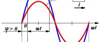
The standard frequency of industrial alternating current in Russia is 50 Hz. Alternating voltage between the contacts of an electrical outlet is created using generators located in power plants. A simplified model of an alternating current generator is a wire frame of area S
, rotating with a circular frequency w in a constant uniform magnetic field with induction B
(Fig. 10
a
).
If we assume that the angle a between the normal to the frame n
and the magnetic induction vector changes in time
t
as a = w
t
, then the magnetic induction flux
Ф
passing through the frame will be equal to:
where the amplitude of EMF oscillations E
Alternating sinusoidal current
Connecting the meter via current transformers
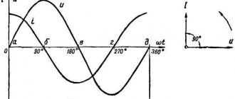
This is the current that changes periodically over time, and its changes obey the sinusoid law. This is the elementary movement of electric charges, therefore it cannot be further decomposed into simple currents.
The type of formula for such an alternating current is:
i = Im*sinωt,
Where:
- Im – amplitude;
- sinωt – phase of sinusoidal current, rad.
Here ω = const is called the angular frequency of alternating electricity, and the angle ωt is in direct time dependence.
Knowing the frequency f of the original current, you can calculate its angular frequency using the expression:
ω = 2πf = 2π/T.
Here 2π is the value of the central angle of the circle expressed in radians:
- T = 2 π radians = 3600;
- T/2 = π = 1800;
- T/4 = π/2 = 900.
If we express 1 rad in degrees, it will be equal to 57°17′.
Sinusoidal alternating motion of electrons
Frequency converters
In this article we will look at what a frequency converter is, the scope of application of frequency converters, their pros and cons, as well as frequency converter circuits.
Frequency converters (or frequency converters)
– electrical equipment for regulating the frequency of alternating voltage. The main scope of application of these devices is changing the rotation speed and torque of asynchronous electric machines. The operating principle of control and regulation is based on the dependence of the speed of rotation of the magnetic field on the frequency of the supply voltage.
Asynchronous electric motors are widely used as drives for industrial equipment, pumping units, control valves and other devices. The main disadvantage of these electric machines is the constant rotation speed and high starting currents. With the help of frequency converters, it is possible to eliminate these shortcomings and significantly expand the scope of application of AC electric motors.
Other quantities related to frequency[ | ]
- Frequency bandwidth
- ν max − ν min {\displaystyle \nu _{max}-\nu _{min}} - Frequency interval
- log ( ν max / ν min ) {\displaystyle \log(\nu _{max}/\nu _{min})} - Frequency deviation
- Δ ν / 2 {\displaystyle \Delta \nu /2} - Period
- 1 / ν {\displaystyle 1/\nu } - Wavelength
- v / ν {\displaystyle {v}/\nu } - Angular velocity
(rotation speed) - d ϕ / dt ; 2 π FBP. {\displaystyle d\phi /dt;2\pi F_{BP.}}
Standard industrial AC frequency in our country
§ 10. alternating electric current
The average AC power in the resistor is determined by the effective values of current and voltage.
If the current varies according to a sinusoidal law, then such a current is called alternating
. Unlike direct current, the voltage of alternating current can be increased or decreased any number of times with virtually no loss of energy. This advantage of alternating current is associated with its widespread use.
The standard frequency of industrial alternating current in Russia is 50 Hz. Alternating voltage between the contacts of an electrical outlet is created using generators located in power plants. A simplified model of an alternating current generator is a wire frame of area S
, rotating with a circular frequency w in a constant uniform magnetic field with induction B
(Fig. 10
a
).
If we assume that the angle a between the normal to the frame n
and the magnetic induction vector changes in time
t
as a = w
t
, then the magnetic induction flux
Ф
passing through the frame will be equal to:
Types of frequency converters
Frequency converters differ in design, principle of operation, and control method. According to their design, frequency converters are divided into two large groups:
Electric machine frequencies.
Electric machine or induction frequency converters are alternating current motors switched on in generator mode. Such electrical devices are used relatively rarely, in conditions where the use of electronic frequency converters is difficult or impossible.
Electronic converters.
Semiconductor CPs consist of a power part made of transistors or thyristors, and a control circuit based on microcontrollers. This electrical equipment is suitable for three-phase and single-phase drives for any purpose. There are emergency situations with a direct connection to the supply network and devices with an intermediate DC link.
Direct frequency converters
Such frequency generators are built on the basis of high-speed thyristor converters connected in bridge, cross, zero and back-to-back circuits.
Devices of this type are connected directly to the power supply.
Advantages of direct frequency converters:
Disadvantages of direct frequency converters:
Frequency converters with intermediate DC link.
Frequency converters of this type are made on the basis of a double conversion circuit. The mains supply voltage is converted to direct voltage, then smoothed and inverted into an alternating output voltage of a given frequency.
Advantages of converters with intermediate DC link:
Disadvantages of converters with intermediate DC link:
Design of converters with intermediate DC link
Such converters consist of several main blocks:
Converter control methods
Based on the control principle, there are 2 main types of frequency converters:
State of emergency with scalar control
Frequency generators of this type produce an output voltage of a certain frequency and amplitude to maintain a certain magnetic flux in the stator windings. Frequency generators with this regulation principle are characterized by relatively low cost and simple design. The lower limit of speed control is about 10% of the rated speed. They can be used to control several motors at once. Scalar variable speed drives are used for drives of pumping units, fans and other devices and equipment where it is not necessary to maintain the rotor speed regardless of the load.
State of emergency with vector control
Microprocessor-based vector control converter devices automatically calculate the interaction of the magnetic fields of the stator and rotor. State of emergency of this type ensures a constant rotor speed regardless of the load. They are used for equipment where it is necessary to maintain the required torque at low speeds, high speed and control accuracy. The use of vector variable speed drives allows you to regulate the rotation speed and set the required torque on the shaft.
VSDs with vector control are divided into sensorless type converters and devices with speed feedback. The latter are used for drives with a wide range of speed control up to 1:1000, the need to position the exact position of the shaft, control torque at low speeds, accurately maintain rotation speed, and start the engine with rated torque. Converters without a speed sensor are used for drives with lower requirements.
Areas of application
Variable frequency drives are used:
The introduction of variable frequency drives provides a significant economic effect. Cost reduction is achieved by reducing energy consumption, repair and maintenance costs of engines and equipment, the ability to use cheaper squirrel-cage asynchronous electric motors, and reducing other production costs. The average payback period for frequency converters ranges from 3 months to three years.
Source