06/30/201606/30/2016 master
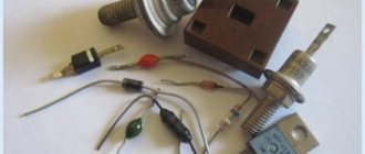
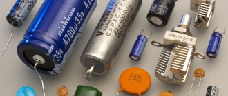
By collecting various electrical devices in their home laboratory, many people not only save money on purchasing new equipment, but also repair broken electrical products. For full operation of many devices, diodes are required, which today come in a wide variety of varieties. In today's article we will talk about an element that is quite often found in electrical circuits - a vacuum diode.
To use such a part correctly, you need to know its structure, as well as what circuit and operating principle are characteristic of it. You will learn about all this from this article.
What is the device
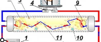
A modern vacuum-type diode is a cylinder made of metal-ceramic or glass , devoid of air. Air is pumped out of this balloon to a pressure of 10-6 - 10-7 mmHg. Art. Hence the name of this element of electrical circuits.
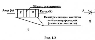
Structure of a vacuum type diode
Inside such a cylinder there are two electrodes. One of them is the cathode. It has the form of a metal vertical cylinder, which is coated with a layer of alkaline earth metal oxide (calcium, strontium, barium). Thanks to this deposition, this element is called an oxide cathode.
Note! When it is heated, significantly greater emission of electrodes occurs from the surface than from a conventional metal element of a similar type.
The cathode inside contains an insulated conductor heated by alternating or direct current. When heated, the cathode emits electrons, which move and reach the second element of the vacuum diode - the anode. The anode has the form of an oval or round cylinder. It has a common axis with the cathode. The circuit of a vacuum type diode is as follows.
Vacuum type diode circuit
In addition to the vacuum diode, there is also such a thing as an electric vacuum diode. A vacuum diode refers to a two-electrode vacuum tube. Its structure is similar to a vacuum type diode. Essentially it's the same thing. Here the cathode is a W-shaped or straight filament. During the operation of such a lamp, it heats up to a certain temperature. As a result of heating, thermionic emission occurs. When a negative voltage is applied to the anode relative to the cathode, electrons are returned back to the cathode. When a positive voltage is applied to the anode, some of the emitted electrons begin to move into it. The result is a current. As a result of their work, vacuum diodes and their analogues are capable of rectifying the voltage applied to them. Vacuum rectifiers have this basic property, which is why they are used as detectors of high-frequency signals and alternating current rectification. This device is typical for all products of this type. At the same time, this device determines the main characteristics of the product, as well as what application it will have.
Note! The frequency range for a vacuum type diode is somewhat limited and does not exceed 500 MHz. At the same time, disk diodes integrated into the waveguides are capable of detecting frequencies up to 10 GHz.
Operating principle
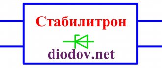
The zener diode was discovered by the American physicist Clarence Melvin Zener, after whom it was named. Electrical breakdown of a pn junction can be caused by a tunnel breakdown (in this case, the breakdown is called Zener breakdown), avalanche breakdown, breakdown as a result of thermal instability, which occurs due to destructive self-heating by leakage currents.
And engineers design these elements in such a way that the occurrence of tunneling and/or avalanche breakdown occurs long before they are likely to experience thermal breakdown.
The magnitude of the breakdown voltage depends on the concentration of impurities and the method of doping of the pn junction. The greater the concentration of impurities and the higher their gradient in the junction, the lower the reverse voltage at which a breakdown occurs.
- A tunnel (Zener) breakdown
appears in a semiconductor in cases where the electric field strength in the pn zone is 106 V/cm. Such high voltage can only occur in highly doped diodes. At breakdown voltages in the range of 4.5...6.7 V, the tunnel and avalanche effects coexist, but at a breakdown voltage less than 4.5 V, only the tunnel effect remains. - In zener diodes with low doping levels or smaller gradients of dopant additives there is only an avalanche breakdown mechanism
, which appears at a breakdown voltage of approximately 4.5 V. And at voltages above 7.2 V, only the avalanche effect remains, and the tunnel effect disappears completely.
As mentioned earlier, when connected directly, the zener diode behaves in the same way as a regular diode when connected directly - it passes current. The differences between them arise when connecting in reverse.
A conventional diode, when connected in reverse, blocks the current, and the zener diode, when the reverse voltage reaches a value called the stabilization voltage, begins to pass current in the opposite direction. This is explained by the fact that when a voltage exceeding U nom is applied to the zener diode. device, a process called breakdown occurs in the semiconductor. The breakdown can be tunnel, avalanche, or thermal. As a result of the breakdown, the current flowing through the zener diode increases to a maximum value limited by the resistor. After reaching the breakdown voltage, the current remains approximately constant over a wide range of reverse voltages. The point at which voltage triggers current can be very precisely set during the manufacturing process by doping. Therefore, each element is assigned a certain breakdown (stabilization) voltage.
The zener diode is used only in “reverse bias” mode, that is, its anode is connected to the “-” power supply. The ability of a zener diode to trigger reverse current when the breakdown voltage is reached is used to regulate and stabilize the voltage when the supply voltage or connected load changes. The use of a zener diode makes it possible to provide a constant output voltage for the connected consumer when the power supply voltage drops or the consumer current changes.
Shapes of the main diode elements
Cathode and anode shape
The cathode included in a vacuum-type diode often has the shape of the Latin letters W or V. This shape is used to increase the length of the product. At the same time, the anode will be more profitable if it is manufactured in the form of a box without side edges. In cross-section, the anode has the shape of a rectangle with rounded corners.
This shape of the anode is determined by the need for it to be at the same distance from the heated cathode in all directions as possible. For this reason, the most advantageous shape for both elements is elliptical. To reduce the degree of heating of the anode, ribs (wings) are often included in its design. Thanks to their presence, the anode has better heat dissipation. Both the cathode and anode in the cylinder are secured using special holders. For greater ease of use, a base consisting of insulating material is installed at the bottom of the lamp. It is equipped with metal pin legs. These pins provide contact for the lamp when it is plugged into the lamp panel sockets. Such a device has an electric vacuum lamp or a vacuum-type diode.
Kenotron console
The kenotron attachment is an oil-filled cylinder, inside of which a transformer and a kenotron are located. A three-limit microammeter for measuring leakage currents with a limit switch is installed on top of the console. The microammeter is calibrated at 200, 1000 and 5000 µA. The shielding design of the microammeter ensures that leakage currents from the device itself are excluded when measuring leakage currents during testing.
rectifier installations made on kenotron lamps KR-110, KRM-150 and KR-220 have a number of disadvantages: emission of x-rays harmful to the human body; small value of rectified current (for the lamps listed above, correspondingly - 5 mA, 10 mA, 30 mA); the presence of incandescent transformers in installations increases their weight; inconvenience of transportation, as a result of which kenotron lamps often fail.
Operating principle of a vacuum type diode
In order for the circuit, which includes a vacuum-type rectifier, to work as it should, you must understand the operating principle of such a part.
Diode operating principle
The operating principle of vacuum diodes is as follows:
- as the cathode heats up, electrons from its surface will begin to separate;
- their separation occurs due to the formation of thermionic emission;
- electrons released from the surface begin to prevent the emission of other electrons. As a result, a cloud of electrons forms around the cathode surface;
- some of the electrons of this cloud, which have the lowest velocities, fall back to the cathode surface;
- in a situation where a certain temperature is set, the electron cloud stabilizes. This means that the same number of electrons fly out from the cathode as are then dropped onto it;
- in the presence of zero voltage, for example, in a situation where the anode is short-circuited to the cathode, an electron current begins to flow in the lamp in the direction from the cathode to the anode. In this situation, the fastest electrons are able to overcome the existing potential well, which is why they are attracted to the anode. Current cutoff occurs in a situation when a negative blocking voltage is applied to the anode. This voltage should be one volt or lower.
- in the situation of applying a positive voltage to the anode, an accelerating field is formed in the diode, which contributes to an increase in the current at the anode. When the current on this element reaches values that are close to the cathode emission limit, the current growth slows down and stabilizes. Those. a “saturation” effect is observed.
This is the principle that vacuum-type diodes operate on.
Relationship between parameters
For electric current to appear, several conditions must be met. We need a source of it, a material that has free charge carriers, and a closed circuit through which they can move. After the invention of the “voltaic column,” scientists began to conduct various experiments studying the flow of electric current. In 1825, Ohm, in his experiments using a galvanic source and torsion balances, observed the loss of energy in charges. He discovered that the current in a circuit depends not only on the type of material, but also on its linear characteristics.
Analyzing the data obtained, Ohm derived the formula: X = a*k/L, where: X is the electric current, a is the electrical voltage, k is the conductivity coefficient, l is the length of the material. Subsequently, this law was confirmed by other scientists and was named after the discoverer.
In its modern form it is written as follows: I = U/R, where:
- U—potential difference (voltage);
- R - resistance.
That is, the current strength in a conductor is directly proportional to the voltage and inversely proportional to its resistance. R is the proportionality coefficient. By its definition, it is the reciprocal of conductivity. Resistance depends on the physical dimensions of the conductor and its ability to prevent the passage of electric current.
An important characteristic of a diode element is the current-voltage characteristic
All diodes, regardless of whether they are vacuum or not, have such a parameter as a current-voltage characteristic, or abbreviated as I-V characteristic.
I-V characteristic of a vacuum diode
To understand what kind of volt-ampere characteristic this is, let’s look at the graph using the example of the processes occurring in the lamp. At the very beginning, when there is no voltage at the anode, an electron cloud forms around the cathode as a result of its heating. When a small positive voltage appears at the anode, the fastest electrons entering the cathode electron cloud begin to rush towards the anode. As a result, it is possible to record a small anode current. In a situation where the anode voltage continues to increase, an increasing number of electrons from the electron cloud will flow to the anode into the flesh until the cathode electron cloud is completely “absorbed.” This state corresponds to point B in the graph above. This voltage means that all electrons escaping from the cathode will be immediately attracted to the anode. Note! There is no further increase in the anode current while maintaining the incandescent value. To achieve an increase in this indicator, it is necessary to use additional electrons. But they are not here. To increase this indicator, the cathode heat can be increased, but this method is not used because it leads to a decrease in the service life of the cathode element. Thus, all cathode emission at a specific filament temperature will be exhausted. As a result, the anode reached a “current saturation” situation. All these processes, step by step, are based on the volt-ampere characteristics given above. A parameter such as the current-voltage characteristic at the highest point can be considered as the limit of the diode's capabilities. As you can see, the operating principle of the product is inseparable from the current-voltage characteristic. Moreover, the latter is his reflection.
General information
In the 16th century, scientific research showed that there is something in nature that can cause interaction forces between bodies. Subsequently, this phenomenon was called electricity, and the quantity characterizing the process was called charge. In 1729, Charles Dufay discovered the existence of two types. Those of the same type have the property of repelling each other, and those of the same type have the property of attraction. They are conventionally divided into positive and negative.
Essentially, electric charge determines the ability of a substance to generate a field and take part in electromagnetic interaction. The SI unit of measurement for a scalar quantity is the coulomb. Charge carriers are elementary particles. They are designated using the symbol q.
The physical body consists of atoms or molecules. In turn, they are formed from the simplest particles. A solid contains nuclei consisting of protons and neutrons. Electrons rotate around them in orbitals. If no external forces act on the body, the system is in electrical equilibrium. This is due to the fact that the positive charge of the nucleus is compensated by the negative charge of the electron.
But at the same time, so-called free electrons can exist in the body. These are particles that have no connection with the nucleus and move freely throughout the body. Their movement is chaotic. Moving along the crystal lattice, electrons collide with defects and impurities, giving them some of their energy and converting it into heat. But this phenomenon is so insignificant that it is difficult to detect even with specialized devices.
If an electromagnetic field is applied to the body, the movement of free charges becomes directed. When ensuring its continuity, a phenomenon occurs that is called electric current. Thus, it came to be understood as the ordered movement of charge carriers. Research has shown that such particles can be:
- electrons are solids;
- ions - gases, electrolytes.
Where are these products used?
The use of vacuum tubes is determined by their basic capabilities or properties, namely the ability to pass current in only one direction. This is due to the fact that in a diode the movement of electrons is only possible from the cathode to the anode. Sometimes this property of diode rectifiers is called one-way conductivity. Due to this property, vacuum diodes are used as a DC-AC converter (its rectification). Such capabilities of this type of product have ensured their extensive use in radio equipment.
Note! The use of a vacuum-type diode will solve the problem of powering radio equipment from an industrial AC network.
The circuit by which you can use a diode as a rectifier for alternating current is quite simple.
Diagram of a diode operating as a rectifier
In this situation, an AC source should be connected between the anode and cathode. The top of the graph shows the AC source voltage. Here there is a periodic change with a certain frequency like a sinusoid. The voltage at the anode changes with the same purity in relation to the cathode. Part of the time the anode will be positive (top of the graph), and part of the time it will be negative (bottom of the graph). With positive half-cycles, there will be a positive voltage at the anode. In such a situation, the current will flow, but with the opposite value of the half-cycle, it will be absent. The result is pulses equal in frequency to alternating current.
Problem solving
Problems associated with finding fundamental electrical quantities are usually simple. But to solve them you will need not only to know several formulas, but also SI units of measurement. In the International System, current is measured in amperes, voltage in volts, resistance in ohms, and power in watts. Often you have to deal with large numbers or, conversely, small ones, so to simplify the notation, prefixes are used: micro, nano, kilo, mega.
Here are some of the typical tasks designed for independent study as part of physics lessons for grade 8:
- Determine the voltage across a resistor with a resistance of 10 ohms if a current of 1 ampere passes through it. This is a simple example solved using Ohm's law. According to him, I = U/R, therefore: U= I*R. Substituting the original data, you can perform the following calculations: U= 1 A*10 Ohm = 10 V.
- Find the power of the device if its resistance is 1 kOhm, when the potential difference created is 10 volts. To calculate P, you need to determine the current consumption: I = U/R = 10/1000 = 0.01 A. Now, using the power formula, you can find the desired parameter: P = I*U = 0.01*10 = 0.1 W .
- An electric lamp is connected to a network with a voltage of 220 V. Find the value of the current passing through the spiral if the conductor resistance is 30 Ohms. According to the law: I = U/R = 220/3 = 7.3 A.
- At a voltage of 220 volts, the current passing through the inductor is 5 A. Calculate how I will change if the voltage increases by 20 volts. Based on the fact that the resistance is constant, we can create a proportion: U1 / I1 = U2/I2. The voltage for the second case can be determined from the expression: U 2 = U + U 1 = 220 + 20 = 240 V. Hence I2 = I1 * U2 / U 1 = 5 A * 240 V / 220 V = 5.45 A.
Source
Generation and recombination of charge carriers
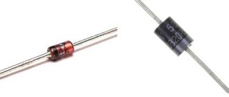
Kd202, 2d202
In electrolytes, semiconductors, and plasma, the processes of recombination and ionization of particles simultaneously occur. Electrically neutral atoms and molecules disintegrate into charged particles - ionization and at the same time particles of different signs are attracted to each other and form electrically neutral particles - recombination. In an equilibrium state, the number of recombination and dissociation events per unit time are equal to each other, and an equilibrium concentration of charge carriers is established in the medium. A system brought out of equilibrium gradually spontaneously transitions to equilibrium. The time constant for establishing an equilibrium charge concentration is called the relaxation time.
The dissociation of neutral particles occurs mainly due to thermal motion and vibration of particles and their collisions. Since dissociation requires some energy, called activation energy, the concentration of charge carriers, if there are no other factors preventing thermal dissociation, increases with increasing temperature. This is why the electrical conductivity of electrolytes, semiconductors, and incompletely ionized plasma increases with increasing temperature. The concentration of charge carriers in a substance depending on temperature is expressed quantitatively by the Arrhenius equation.
The mechanism of dissociation into charged particles is known through external non-thermal influence, for example, electromagnetic radiation or a flow of fast particles, for example, a flow of electrons, ionizing radiation. With this effect, the concentration of charge carriers increases compared to the equilibrium thermal concentration. The absorption of a photon or a charged particle in a semiconductor generates, with some probability, an electron-hole pair; this phenomenon is used in various semiconductor photodetectors and semiconductor particle detectors. Macroscopically, an increase in the concentration of charge carriers manifests itself in a change in electrical properties, for example, electrical conductivity.
The recombination of charged particles is accompanied by the release of energy equal to the dissociation energy or ionization energy. In most cases, this energy turns into thermal motion, but it can transform into other types of energy, for example, carried away by a photon, as in LEDs and semiconductor lasers in acts of recombination of electron-hole pairs.
Interesting Facts
- In the first decades of the development of semiconductor technology, the manufacturing accuracy of diodes was so low that it was necessary to “sort out” already manufactured devices. Thus, the D220 diode could, depending on the actual parameters obtained, be marked both as a switch (D220A, B) and as a stabistor (D220S) [ source not specified 4049 days
]. Radio amateurs widely used it as a varicap. - Diodes can be used as temperature sensors.
- Diodes in a transparent glass case (including modern SMD versions) may have parasitic sensitivity to light (that is, a radio-electronic device operates differently in the case and without the case, in the light). There are amateur radio circuits in which ordinary diodes are used as a photodiode and even as a solar battery.
Charge carrier free path
The average distance over which the movement of a charge carrier can be considered independent of the presence of other particles is called the mean free path. Usually this distance is equal to the path length of a particle before colliding with another particle, but for example, in plasma, the path length is considered to be the distance to a significant electrostatic interaction with another charged plasma particle and a change in the direction of movement.
In electrolytes, the mean free path is limited by collisions; in metals, the mean free path of electrons is limited by the scattering of electrons on atoms, crystal lattice defects and its thermal vibrations - scattering on phonons.
In semiconductors, electrons and holes are scattered by crystal lattice defects, impurity atoms, and phonons. In pure semiconductors, the mean free path can reach several millimeters at low temperatures.
In a vacuum and rarefied plasma, the concept of mean free path loses its meaning, since particles do not interact. Conventionally, we can assume that the free path is equal to the dimensions of the vessel.
The higher the mean free path λ{\displaystyle \lambda } and the higher the carrier concentration n{\displaystyle n}, the higher the electrical conductivity σ{\displaystyle \sigma }:
σ≈λ⋅n.{\displaystyle \sigma \approx \lambda \cdot n.}