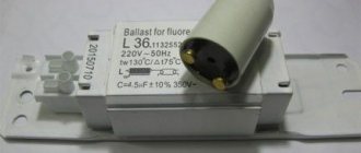
Fluorescent lamps (FLLs) are widely used to illuminate both large areas of public premises and as household light sources. The popularity of fluorescent lamps is largely due to their economic characteristics. Compared to incandescent lamps, this type of lamp has high efficiency, increased light output and a longer service life. However, a functional disadvantage of fluorescent lamps is the need for a starting starter or a special ballast (ballast). Accordingly, the task of starting the lamp when the starter fails or is absent is urgent and relevant.
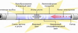
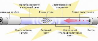
The fundamental difference between an LDS and an incandescent lamp is that the conversion of electricity into light occurs due to the flow of current through mercury vapor mixed with an inert gas in a bulb. Current begins to flow after breakdown of the gas by high voltage applied to the electrodes of the lamp.
- Throttle.
- Lamp bulb.
- Luminescent layer.
- Starter contacts.
- Starter electrodes.
- Starter housing.
- Bimetallic plate.
- Lamp filaments.
- Ultraviolet radiation.
- Discharge current.
The resulting ultraviolet radiation lies in the part of the spectrum invisible to the human eye. To convert it into a visible light flux, the walls of the bulb are coated with a special layer, a phosphor. By changing the composition of this layer, you can obtain different light shades. Before the direct start-up of the LDS, the electrodes at its ends are heated by passing a current through them or due to the energy of a glow discharge. High breakdown voltage is provided by ballasts, which can be assembled according to a well-known traditional circuit or have a more complex design.
Starter operating principle
In Fig. Figure 1 shows a typical connection of an LDS with a starter S and a choke L. K1, K2 – lamp electrodes; C1 is a cosine capacitor, C2 is a filter capacitor. A mandatory element of such circuits is a choke (inductor) and a starter (chopper). The latter is often used as a neon lamp with bimetallic plates. To improve the low power factor due to the presence of inductor inductance, an input capacitor is used (C1 in Fig. 1).
Rice. 1 Functional diagram of LDS connection
The phases of starting the LDS are as follows: 1) Warming up the lamp electrodes. In this phase, the current flows through the circuit “Network – L – K1 – S – K2 – Network”. In this mode, the starter begins to close/open randomly. 2) At the moment the circuit is broken by the starter S, the magnetic field energy accumulated in the inductor L is applied in the form of high voltage to the electrodes of the lamp. An electrical breakdown of the gas inside the lamp occurs. 3) In breakdown mode, the lamp resistance is lower than the resistance of the starter branch. Therefore, the current flows along the circuit “Network – L – K1 – K2 – Network”. In this phase, inductor L acts as a current-limiting reactor. Disadvantages of the traditional LDS starting circuit: acoustic noise, flickering with a frequency of 100 Hz, increased start-up time, low efficiency.
Advantages and disadvantages of EmPRA
The electromagnetic choke for fluorescent lamps is characterized by low price, simple design and high reliability.
In addition, there are disadvantages:
- pulsating light, leading to eye fatigue;
- up to 15% of electricity is lost;
- noise at startup and during operation;
- the lamp does not start well at low temperatures;
- large size and weight;
- long lamp startup.
Typically, humming and flickering of the lamp occurs when the power supply is unstable. Ballasts are produced with different noise levels. To reduce it, you can choose a suitable model.
Lamps and chokes are selected equal to each other in power, otherwise the service life of the lamp will be significantly reduced. Usually they are supplied as a set, and the ballast is replaced with a device with the same parameters.
Complete with electronic ballasts, they are inexpensive and do not require configuration.
The ballast is characterized by the consumption of reactive energy. To reduce losses, a capacitor is connected in parallel to the power supply network.
Operating principle of electronic ballasts
Electronic ballasts (EPG) use the potential of modern power electronics and are more complex, but also more functional circuits. Such devices allow you to control the three startup phases and adjust the light output. The result is longer lamp life. Also, due to the lamp being powered with a current of a higher frequency (20÷100 kHz), there is no visible flicker. A simplified diagram of one of the popular electronic ballast topologies is shown in Fig. 2.
Rice. 2 Simplified circuit diagram of electronic ballasts In Fig. 2 D1-D4 – mains voltage rectifier, C – filter capacitor, T1-T4 – transistor bridge inverter with transformer Tr. Optionally, the electronic ballast may contain an input filter, a power factor correction circuit, additional resonant chokes and capacitors. A complete schematic diagram of one of the typical modern electronic ballasts is shown in Fig. 3.
Rice. 3 Circuit diagram of BIGLUZ electronic ballasts The circuit (Fig. 3) contains the main elements mentioned above: a bridge diode rectifier, a filter capacitor in the DC link (C4), an inverter in the form of two transistors with wiring (Q1, R5, R1) and (Q2, R2 , R3), inductor L1, transformer with three terminals TR1, trigger circuit and lamp resonant circuit. Two windings of the transformer are used to turn on transistors, the third winding is part of the resonant circuit of the LDS.
Electronic ballast
All the shortcomings of the electromagnetic choke had to be eliminated, and as a result of research, an electronic choke for fluorescent lamps (ECG) was created. The circuit is a single unit that starts and maintains the combustion process by forming a specified sequence of voltage changes. You can connect it using the instructions included with the model.
The choke for electronic fluorescent lamps has the following advantages:
- possibility of instant start or with any delay;
- lack of starter;
- no blinking;
- increased light output;
- compactness and lightness of the device;
- optimal operating modes.
Electronic ballasts are more expensive than electromagnetic devices due to the complex electronic circuitry, which includes filters, power factor correction, inverter and ballast. Some models are equipped with protection against erroneous starting of the lamp without lamps.
User reviews talk about the convenience of using electronic ballasts in energy-saving LDS, which are built directly into bases for ordinary standard cartridges.
Methods for starting LDS without specialized ballasts
When a fluorescent lamp fails, there are two possible reasons: 1) . In this case, it is enough to replace the starter. The same operation should be carried out if the lamp flickers. In this case, upon visual inspection, there are no characteristic darkening on the LDS flask. 2) . Perhaps one of the electrode threads has burned out. Upon visual inspection, darkening may be noticeable at the ends of the bulb. Here you can use known starting circuits to continue operating the lamp even with burnt-out electrode threads. For emergency starting, a fluorescent lamp can be connected without a starter according to the diagram below (Fig. 4). Here the user plays the role of starter. Contact S1 is closed for the entire period of lamp operation. Button S2 is closed for 1-2 seconds to light the lamp. When S2 opens, the voltage on it at the moment of ignition will be significantly higher than the mains voltage! Therefore, extreme caution should be exercised when working with such a scheme.
Rice. 4 Schematic diagram of starting an LDS without a starter If you need to quickly ignite an LDS with burnt filaments, then you need to assemble a circuit (Fig. 5).
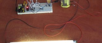
Rice. 5 Schematic diagram of connecting an LDS with a burnt filament For a 7-11 W inductor and a 20 W lamp, the C1 rating is 1 μF with a voltage of 630 V. Capacitors with a lower rating should not be used. Automatic circuits for starting an LDS without a choke involve using an ordinary incandescent lamp as a current limiter. Such circuits, as a rule, are multipliers and supply the LDS with direct current, which causes accelerated wear of one of the electrodes. However, we emphasize that such circuits allow you to run even an LDS with burnt-out electrode threads for some time. A typical connection diagram for a fluorescent lamp without a choke is shown in Fig. 6.
Rice. 6. Block diagram of connecting an LDS without a choke
Rice. 7 Voltage on the LDS connected according to the diagram (Fig. 6) until the moment of start-up As we see in Fig. 7, the voltage on the lamp at the moment of starting reaches the level of 700 V in approximately 25 ms. Instead of an HL1 incandescent lamp, you can use a choke. Capacitors in the diagram of Fig. 6 should be selected within 1÷20 µF with a voltage of at least 1000V. Diodes must be designed for a reverse voltage of 1000V and a current of 0.5 to 10 A, depending on the lamp power. For a 40 W lamp, diodes rated for current 1 will be sufficient. Another version of the starting circuit is shown in Fig. 8.
Rice. 8 Schematic diagram of a multiplier with two diodes. Parameters of capacitors and diodes in the circuit in Fig. 8 are similar to the diagram in Fig. 6. One of the options for using a low-voltage power supply is shown in Fig. 9. Based on this circuit (Fig. 9), you can assemble a wireless fluorescent lamp on a battery.
Rice. 9 Schematic diagram of connecting an LDS from a low-voltage power source For the above diagram, it is necessary to wind a transformer with three windings on one core (ring). As a rule, the primary winding is wound first, then the main secondary (indicated as III in the diagram). Cooling must be provided for the transistor.
Ignition without electromagnetic ballast
To extend the life of burnt-out fluorescent lamps, you can install one of the switching circuits without a choke and starter. For this purpose, voltage multipliers are used.
Diagram for switching on fluorescent lamps without a choke
The filaments are short-circuited and voltage is applied to the circuit. After straightening, it increases 2 times, and this is enough for the lamp to light up. Capacitors (C 1), (C 2) are selected for a voltage of 600 V, and (C 3), (C 4) - for a voltage of 1000 V.
The method is also suitable for working LLs, but they should not operate with DC power. After some time, mercury accumulates around one of the electrodes, and the brightness of the glow decreases. To restore it, you need to turn the lamp over, thereby changing the polarity.
How to turn on a fluorescent lamp - without a choke
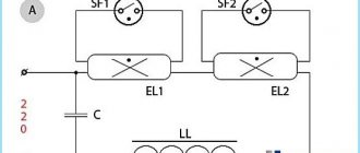
The figure shows two ways to connect fluorescent lamps:
schematic diagram for switching on a fluorescent lamp with starter ignition (Fig. 1, a) and switching on a fluorescent lamp without a choke (Fig. 1, b).
For both schemes for switching on fluorescent lamps, the increased voltage pulse that promotes the formation of an arc discharge in the lamps (necessary for their ignition) is the inductor LL and the incandescent lamp EL2.
The second diagram (Fig. 1, b) shows a circuit for switching on a fluorescent lamp using an incandescent lamp (instead of a choke). In this circuit there is a current-carrying wire, one end of which is connected to one of the terminals of the electrodes of the fluorescent lamp. Instead of a live wire, you can use a wide strip of foil, which has the same electrical connection as the wire. Accordingly, both the piece of wire itself and the strip of foil must be secured at the ends of the bulb with metal clamps corresponding to the diameter of the bulb (fluorescent lamp).
That's all for now. Follow the section.
(electronic ballasts) fluorescent lamps burn out. This happens with large fixtures and with compact fluorescent lamps (CFLs), better known as energy-saving lamps. And if burnt electronics can be repaired, they are simply thrown away.
It is clear that if one of the filaments of a lamp connected before the choke with a starter or to an electronic ballast burns out, the lamp will no longer turn on. In addition, the old “Brezhnev” connection scheme has several more disadvantages: prolonged starting with the starter, accompanied by annoying blinking; lamp flickering at twice the mains frequency.
However, the solution is simple - power the fluorescent lamp not with alternating current, but with direct current, and in order not to use capricious starters, you need to apply increased mains voltage when starting. Thus, not only will the light source stop flickering, but after connecting according to the new circuit, even a burnt-out fluorescent lamp will work for many more years.
To start with a multiplied network voltage, you will not need to heat the coils - electrons for initial ionization will be torn out at room temperature, even from burnt-out coils. Since heating to a temperature of 800–900 degrees is not required for a glowing starting discharge, the service life of any fluorescent lamp, even with intact spirals, is dramatically extended. Once started, the filament pieces become warm due to the steady flow of electrons. The simplest scheme that has these advantages is the following:
The figure shows the circuit of a full-wave rectifier with voltage doubling, here the lamp lights up instantly
When connecting according to this scheme, you need to connect together both external terminals of each lamp filament - no matter whether they are burnt out or intact.
Capacitors C1, C4 need non-polar ones with an operating voltage of more than 2 times the network voltage (for example, MBM not lower than 600 volts). This is the main disadvantage of the circuit - it uses two high-capacity capacitors for high voltage. Such capacitors have significant dimensions.
Capacitors C2, C3 also need to be non-polar and it is desirable that they be mica for a voltage of 1000 V. On diodes D1, D4 and capacitors C2, C3, the voltage jumps to 900 V, which ensures reliable ignition of a cold lamp. Also, these two containers help suppress radio interference. The lamp can be lit without these capacitors and diodes, but with them, switching on becomes more trouble-free.
The resistor must be wound independently from nichrome or manganin wire. The power dissipated by it is significant, since a luminous fluorescent lamp does not have its own internal resistance.
Detailed ratings of circuit elements depending on the power of the lamp are given in the table:
You can use diodes not necessarily indicated in the table, but similar modern ones, the main thing is that they are suitable in power.
To light a stubborn lamp, wrap a foil ring around one end and connect it with a wire to a spiral on the opposite side. Such a 50 mm wide rim is cut out of thin foil and glued to the lamp bulb.
It should be noted that a fluorescent lamp is not at all designed to operate on direct current. With such power supply, the light flux from it weakens over time due to the fact that mercury vapor inside the tube gradually collects near one of the electrodes. Although, it is quite easy to restore the brightness of the glow; you just need to turn the lamp over, swapping the plus and minus at its ends. And in order not to disassemble the lamp at all, it makes sense to install a switch in it in advance.
Of course, it will not be possible to fit such a circuit into the base of a small CFL. But why is this necessary? You can assemble the entire starting circuit in a separate box and connect it to the lamp through long wires. It is important to remove all electronics from the energy-saving lamp, and also short-circuit the two terminals of each filament. The main thing is not to forget and not to put a working lamp into such a homemade lamp.
Homemade wind generator. Wind generator based on an asynchronous motor Connecting fluorescent lamps via electronic ballasts
A fluorescent lamp is a light source where the glow is achieved by creating an electrical discharge in an environment of inert gas and mercury vapor. As a result of the reaction, an ultraviolet glow, invisible to the eye, appears, affecting the phosphor layer located on the inner surface of the glass bulb. The standard connection diagram for a fluorescent lamp is a device with an electromagnetic balance (EMB).
Electronic ballast
Electronic ballast control circuitry has replaced older daylight sources to eliminate their inherent shortcomings. Electromagnetic ballast consumes excess energy, often makes noise, breaks down and damages the lamp. In addition, the lamps flicker due to the low frequency of the supply voltage.
Electronic ballasts are an electronic unit that takes up little space. Fluorescent lamps are easy and quick to start, without creating noise and providing uniform illumination. The circuit provides several ways to protect the lamp, which increases its service life and makes its operation safer.
The electronic ballast works as follows:
- Warming up the LL electrodes. Start-up is quick and smooth, which increases lamp life.
- Ignition is the generation of a high voltage pulse that pierces the gas in the flask.
- Combustion is the maintenance of a small voltage on the lamp electrodes, which is sufficient for a stable process.
Electronic throttle circuit
First, the alternating voltage is rectified using a diode bridge and smoothed by a capacitor (C 2). Next, a half-bridge high-frequency voltage generator using two transistors is installed. The load is a toroidal transformer with windings (W1), (W2), (W3), two of them are connected in antiphase. They alternately open the transistor switches. The third winding (W3) supplies resonant voltage to the LL.
A capacitor (C 4) is connected in parallel to the lamp. Resonant voltage is supplied to the electrodes and penetrates the gaseous environment. By this time the filaments have already warmed up. Once ignited, the lamp's resistance drops sharply, causing the voltage to drop sufficiently to maintain combustion. The startup process lasts less than 1 second.
Electronic circuits have the following advantages:
- start with any specified time delay;
- installation of a starter and a massive throttle is not required;
- the lamp does not blink or hum;
- high-quality light output;
- compactness of the device.
The use of electronic ballasts makes it possible to install it in the base of a lamp, which is also reduced to the size of an incandescent lamp. This gave rise to new energy-saving lamps that can be screwed into a regular standard socket.
During operation, fluorescent lamps age and require an increase in operating voltage. In the electronic ballast circuit, the ignition voltage of the glow discharge at the starter decreases. In this case, its electrodes may open, which will trigger the starter and turn off the LL. Then it starts again. Such blinking of the lamp leads to its failure along with the inductor. In an electronic ballast circuit, a similar phenomenon does not occur, since the electronic ballast automatically adjusts to changes in the parameters of the lamp, selecting a favorable mode for it.
The device of fluorescent lamps
In most light bulbs, the bulb is shaped like a cylinder. More complex geometric shapes are found. At the ends of the lamp there are electrodes, reminiscent in design of the spirals of incandescent light bulbs. The electrodes are made of tungsten and soldered to the pins located on the outside. Voltage is applied to these pins.
A gas environment is created inside the fluorescent lamp, which is characterized by negative resistance, which manifests itself when the voltage between the electrodes located opposite each other decreases.
The lamp switching circuit uses a choke (ballast). Its task is to generate a significant voltage pulse, due to which the light bulb will turn on. The kit includes a starter, which is a glow discharge lamp with a pair of electrodes in an inert gas environment. One of the electrodes is a bimetallic plate. When turned off, the electrodes of the fluorescent light bulb are open.
The figure below shows a diagram of the operation of a fluorescent lamp.
How does a fluorescent lamp work?
The operating principles of fluorescent light sources are based on the following principles:
- Voltage is sent to the circuit. However, at first the current does not reach the light bulb due to the high voltage of the environment. The current moves through the spirals of the diodes, gradually heating them. The current is supplied to the starter, where the voltage is sufficient to produce a glow discharge.
- As a result of the heating of the starter contacts by the current, the bimetallic plate shorts. The metal takes on the functions of a conductor, and the discharge ends.
- The temperature in the bimetallic conductor drops, and the contact in the network opens. The inductor creates a high voltage pulse as a result of self-induction. As a result, the fluorescent light bulb lights up.
- A current flows through the lighting fixture, which is halved as the voltage across the inductor is reduced. It is not enough to start the starter again, the contacts of which are open when the light is on.
To create a circuit for switching on two light bulbs installed in one lighting fixture, you need a common choke. The lamps are connected in series, but each light source has a parallel starter.
Ignition circuits with electronic ballasts
A device with a throttle and starter works according to the following principle:
- Supplying voltage to the electrodes. The current does not pass through the gaseous medium of the lamp at first due to its high resistance. It enters through the starter (St) (Fig. below), in which a glow discharge is formed. In this case, a current passes through the spirals of the electrodes (2) and begins to heat them up.
- The starter contacts heat up, and one of them closes, since it is made of bimetal. The current passes through them and the discharge stops.
- The starter contacts stop heating up, and after cooling, the bimetallic contact opens again. A voltage pulse occurs in the inductor (D) due to self-induction, which is sufficient to ignite the LL.
- A current passes through the gaseous medium of the lamp; after starting the lamp, it decreases along with the voltage drop across the inductor. The starter remains disconnected, since this current is not enough to start it.
Fluorescent lamp connection diagram
Capacitors (C 1) and (C 2) in the circuit are designed to reduce the level of interference. A capacitance (C 1) connected in parallel to the lamp helps reduce the amplitude of the voltage pulse and increase its duration. As a result, the service life of the starter and LL increases. The capacitor (C 2) at the input provides a significant reduction in the reactive component of the load (cos φ increases from 0.6 to 0.9).
If you know how to connect a fluorescent lamp with burnt-out filaments, it can be used in an electronic ballast circuit after a slight modification of the circuit itself. To do this, the spirals are short-circuited and a capacitor is connected in series to the starter. According to this scheme, the light source will be able to work for some more time.
A widely used switching method is with one choke and two fluorescent lamps.
Switching on two fluorescent lamps with a common choke
2 lamps are connected in series between each other and the choke. Each of them requires the installation of a parallel connected starter. To do this, use one output pin at the ends of the lamp.
For LLs, it is necessary to use special switches so that their contacts do not stick due to high inrush current.
Connection options
Let's consider different options for connecting a fluorescent lamp.
Connection using electromagnetic balance (EMB)
The most common type of connection for a fluorescent light source is a circuit with a starter, where electronic ballasts are used. The principle of operation of the circuit is based on the fact that as a result of connecting the power, a discharge occurs in the starter and the bimetallic electrodes are short-circuited.
The current in the electrical circuit of the conductors and starter is limited only by the internal choke resistance. As a result, the operating current in the light bulb increases almost threefold, the electrodes rapidly heat up, and after the conductors lose temperature, self-induction occurs and the lamp ignites.
Disadvantages of the scheme:
- Compared to other methods, this is a rather expensive option in terms of energy consumption.
- Start-up takes at least 1 – 3 seconds (depending on the degree of wear of the light source).
- Inability to work at low air temperatures (for example, in an unheated basement or garage).
- There is a stroboscopic effect of flashing the light bulb. This factor negatively affects human vision. Such lighting cannot be used for production purposes, because fast moving objects (for example, a workpiece in a lathe) appear motionless.
- Unpleasant humming of the throttle plates. As the device wears out, the sound increases.
The switching circuit is designed in such a way that it has one choke for two light bulbs. The inductance of the inductor should be enough for both light sources. 127 volt starters are used. They are not suitable for a single-lamp circuit; 220 Volt devices are needed there.
The picture below shows a chokeless connection. The starter is missing. The circuit is used in case of burnout of filament lamps.
A step-up transformer T1 and a capacitor C1 are used, which limits the current flowing through the light bulb from a 220-volt network.
The following circuit is used for light bulbs with burnt out filaments. However, there is no need for a step-up transformer, making the design of the device simpler.
Below is shown a method of using a diode rectifier bridge, which eliminates the flickering of a light bulb.
The figure below shows the same technique, but in a more complex design.
Two tubes and two chokes
To connect a fluorescent lamp, you can use a serial connection:
- The phase from the wiring is sent to the inductor input.
- From the inductor output, the phase goes to the contact of the light source (1). From the second contact it is sent to the starter (1).
- From the starter (1) it goes to the second contact pair of the same light bulb (1). The remaining contact is connected to zero (N).
Connect the second tube in the same way. First the inductor, then one contact of the light bulb (2). The second contact of the group is sent to the second starter. The starter output is combined with the second pair of light source contacts (2). The remaining contact should be connected to input zero.
Connection diagram for two lamps from one choke
The scheme provides for the presence of two starters and one choke. The most expensive element of the circuit is the inductor. A more economical option is a two-lamp lamp with a choke. The video explains how to implement the scheme.
The disadvantages of the electronic ballast circuit necessitated the search for a more optimal connection method. During the research, a method involving electronic ballast was invented. In this case, it is not the mains frequency (50 Hz) that is used, but high frequencies (20 – 60 kHz). It is possible to get rid of the flashing light that is harmful to the eyes.
Externally, the electronic ballast is a block with terminals exposed to the outside.
The inside of the device contains a printed circuit board on which the entire circuit can be assembled. The unit is small in size, thanks to which it fits into the housing of even a small lighting device. Switching on is much faster compared to the EMPA standard. The operation of the device does not cause acoustic discomfort. This connection method is called starterless.
It is not difficult to understand the principle of operation of a device of this type, since there is a diagram on its reverse side. It shows the number of lamps for connection and explanatory notes. There is information about the power of the light bulbs and other technical parameters of the device.
The connection is made as follows:
- The first and second contacts are connected to a pair of lamp contacts.
- The third and fourth contacts are directed to the remaining pair.
- Power is supplied to the input.
Using Voltage Multipliers
This option allows you to connect a fluorescent lamp without using an electromagnetic balance. Usually used to increase the service life of light bulbs. The connection diagram for burnt-out lamps makes it possible for the light sources to work for some more time, provided that their power is no more than 20 - 40 W. Filaments are allowed both suitable for work and burnt out. In any case, the thread leads must be short-circuited.
As a result of rectification, the voltage doubles, so the light bulb turns on almost instantly. Capacitors C1 and C2 are selected based on an operating voltage of 600 Volts. The disadvantage of capacitors is their large size. As capacitors C3 and C4, preference is given to mica devices rated at 1000 Volts.
Fluorescent lamps are not compatible with direct current. Very soon, so much mercury accumulates in the device that the light becomes noticeably weaker. To restore the brightness of the glow, change the polarity by turning the bulb over.
Alternatively, you can install a switch so you don't have to remove the lamp every time.
Connection without starter
The method using a starter involves prolonged heating of the light bulb. In addition, this part must be changed frequently. A scheme where the electrodes are heated using old transformer windings allows you to do without a starter. The transformer acts as ballast.
Bulbs used without a starter must be marked RS (quick start). A light source started through a starter is not suitable, since its conductors take a long time to heat up and the spirals burn out quickly.
Serial connection of two light bulbs
In this case, it is necessary to connect two fluorescent lamps with one ballast. All devices are connected in series.
To carry out electrical work you will need the following parts:
- induction throttle;
- starters (2 units);
- fluorescent light bulbs.
The connection is made in the following order:
- We connect starters to each light bulb. The connection is made in parallel. The connection point is the pin input at the ends of the lighting device.
- We direct free contacts to the electrical network. We use a choke for connection.
- We connect capacitors to the contacts of the light source. They will allow you to reduce the intensity of interference in the network and compensate for power reactivity.
Note! In standard household switches (especially in inexpensive models), contacts often stick due to too high starting currents. In this regard, it is recommended to purchase high-quality switches for use in conjunction with fluorescent lamps.
Replacing the lamp
If there is no light and the cause of the problem is only to replace a burnt out light bulb, proceed as follows:
- Let's disassemble the lamp. We do this carefully so as not to damage the device. Rotate the tube along its axis. The direction of movement is indicated on the holders in the form of arrows.
- When the tube is rotated 90 degrees, lower it down. The contacts should come out through the holes in the holders.
- The contacts of the new light bulb must be in a vertical plane and fit into the hole. When the lamp is installed, turn the tube in the opposite direction. All that remains is to turn on the power supply and check the system for functionality.
- The final step is the installation of a diffuser lamp.
System health check
After connecting the fluorescent lamp, you should make sure that it is working and that the ballasts are in good working order. To carry out the tests, you will need a tester with which to check the cathode filaments. The permissible resistance level is 10 ohms.
If the tester determines the resistance to be infinite, it is not necessary to throw away the light bulb. This light source still retains functionality, but it must be used in cold start mode. In the normal state, the starter contacts are open, and its capacitor does not allow direct current to pass through. In other words, the ringing should show a very high resistance, which sometimes reaches hundreds of ohms.
After touching the choke terminals with the ohmmeter probes, the resistance gradually decreases to a constant value inherent in the winding (several tens of Ohms).
Note! The faulty state of the throttle is indicated by the burnout of a recently installed light bulb.
It is not possible to reliably determine the turn-to-turn short circuit in the inductor winding using a conventional ohmmeter. However, if the device has an inductance measurement function and data on electronic ballasts, a discrepancy between the values will indicate a problem.