Don't get in. Will kill! (With)
I will try to explain the work with diodes, LEDs, as well as zener diodes on the fingers.
Experienced electronics engineers may skip the article because they will not discover anything new for themselves. I will not go into the theory of electron-hole conductivity of the pn junction. I believe this teaching approach will only confuse beginners. This is a bare theory that has almost no relation to practice. However, for those interested in the theory, I suggest this article. Everyone is welcome under cat. This is the second article in the electronics series. I also recommend reading the first one, which tells about what electric current and voltage are. A diode is a semiconductor device that has 2 terminals for connection. It is made, simply put, by connecting 2 semiconductors with different types of impurities, they are called donor and acceptor, n and p, respectively, so the diode contains a pn junction inside. The terminals, usually made of tinned copper, are called the anode (A) and cathode (K). These terms go back to the times of vacuum tubes and are used in writing to indicate the directionality of the diode. Graphic notation is much simpler. The names of the diode terminals will be remembered by themselves when used in practice.
As I already wrote, we will not use the theory of electron-hole conductivity of the diode. Let's just encapsulate this theory down to a black box with two terminals for connection. In much the same way, programmers encapsulate working with third-party libraries without going into the fucking details of their work. Or, for example, when, when using a vacuum cleaner, we do not go into detail about how it works inside, it just works and one of the properties of the vacuum cleaner is important to us - sucking dust.
Let's look at the properties of the diode, the most obvious:
- From anode to cathode, this direction is called direct, the diode passes current.
- From the cathode to the anode, in the opposite direction, the diode does not pass current. (Actually no. But more on that later.)
- When current flows in the forward direction, some voltage drops across the diode.
Perhaps these properties are already well known to you.
But there are some additions. What is considered forward and what is backward? Direct connection is called when the voltage at the anode is greater than at the cathode. The opposite is the opposite. Direct and reverse inclusion is a convention. In real circuits, the voltage on the same diode can change from direct to reverse and vice versa. A silicon diode begins to pass any significant current only when the voltage at the anode is approximately 0.65 V higher than at the cathode. No not like this. When any current flows, a voltage drop is formed across the diode, approximately equal to 0.65 V or higher.
A voltage of 0.65 V is called the forward voltage drop across the pn junction. This is only an approximate average value, it depends on the current, crystal temperature and diode manufacturing technology. When the flowing current changes, it changes nonlinearly. To somehow indicate this nonlinearity graphically, manufacturers take the current-voltage characteristics of the diode. In powerful high-voltage diodes, the voltage drop can be 2, 3, etc. greater. times. This means that several pn junctions are connected in series inside the diode.
To determine the voltage drop, you can use the current-voltage characteristic (CV) of the diode in the form of a graph. Sometimes these graphs are given in datasheets for real diode models, but more often they are not. The first graph I came across below shows the current-voltage characteristics of the KD243A, although this is not important, they are all approximately similar.
On the graph, Upr is the forward voltage drop across the diode. Ipr – current flowing through the diode. The graph shows what the voltage drop across the diode will be when the nth current flows. But most often, datalists do not show real current-voltage characteristics, but rather the forward voltage drop indicated at a certain current. In English literature, voltage drop is designated as forward voltage.
How to use
The voltage drop across a diode is a bad characteristic for us, since this voltage does no useful work and is dissipated as heat on the diode body. The smaller the drop, the better. Typically, the voltage drop across a diode is determined based on the current flowing through the diode. For example, let's connect a diode in series with the load. Essentially, this will protect the circuit from over-reversing, in case the power supply is detachable. In the figure below, a 47 Ohm resistor is taken as the protected circuit, although in reality it can be anything, for example, a section of a large circuit. The power supply is a 12 V battery.
Let's say the load without a diode consumes 255 mA.
In this case, this can be calculated using Ohm's law: I= U / R = 12 / 47 = 0.255 A or 255 mA. Although usually the consumption of a spherical circuit in a vacuum is already known, at least based on the maximum characteristics of the power supply. Let's find on the I-V curve indicated above the voltage drop for the KD243A diode at 0.255 A of flowing current, at 25 degrees. It is equal to approximately 0.75 V. These 0.75 V will drop across the diode, and 12 will remain to power the circuit - 0.75 = 11.25 V - sometimes it may not be enough. As a bonus, you can find the power released in the form of heat and losses on the diode using the formula P = I * U = 0.75 * 0.255 = 0.19 W, where I and U are the current through the diode and the voltage drop across the diode. What to do when the current-voltage curve is not available? For example, for the popular 1n4007 diode, only the forward voltage is specified as 1 V at a current of 1 A. You need to use this value, or measure the actual drop. And if this value is not specified for any diode, then an average of 0.65 V will do. In reality, it is easier to measure this voltage drop with a voltmeter in the circuit than to look for it in graphs. I think there is no need to explain that the voltmeter should be switched on to a constant voltage if a direct current flows through the diode, and the probes should touch the anode and cathode of the diode.
A little about other characteristics
In the previous example, if you turn the battery over, I mean reverse the polarity, see the bottom figure, no current will flow and the voltage drop across the diode in the worst case will be 12 V - the battery voltage.
The main thing is that this voltage does not exceed the breakdown voltage of our diode, also known as reverse voltage, also known as breakdown voltage. And one more condition is also important: the current in the forward direction through the diode does not exceed the rated current of the diode, also known as forward current. These are the two main parameters by which a diode is selected: forward current and reverse voltage. Sometimes data sheets also indicate the diode's power dissipation or rated power (power dissipation). If it is specified, it cannot be exceeded. We have already figured out how to calculate it in the previous example. But if the power is not indicated, then you need to focus on the current.
They say that in the opposite direction no current flows through the diode, or almost no current flows. In fact, a leakage current flows through it, reverse current in English literature. This current is very small, from several nanoamperes for low-power diodes to several hundred microamperes for high-power ones. Also, this current depends on the temperature and applied voltage. In most cases, the leakage current does not play any role, for example, as in the previous example, but when you work with nanoamps and put some kind of protection diode at the input of the op-amp, then oh... The circuit will behave completely differently, as I intended.
Diodes also have some small parasitic capacitance. That is, in essence, it is a capacitor connected in parallel with a diode. This capacity must be taken into account during fast processes when the diode is operating in a circuit with tens to hundreds of megahertz.
Also a few words about the term “nominal”. Typically, current and voltage ratings indicate that if these parameters are exceeded, the manufacturer does not guarantee the operation of the product, unless otherwise stated. And this is for all electronic components, not just the diode.
What else can you do
There are many applications for diodes.
Radio electronics designers usually invent their circuits from pieces of other circuits, the so-called building bricks. Here are some options. For example, a circuit for protecting digital or analog inputs from overvoltage:
The diodes in this circuit do not pass current during normal operation. Only leakage current. But when an overvoltage with a positive half-wave occurs at the input, i.e. the input voltage becomes greater than Upit plus the forward voltage drop across the diode, then the upper diode opens and the input is closed to the power bus. If a negative half-wave voltage occurs, the lower diode opens and the input is shorted to ground. In this circuit, by the way, the less leakage and capacitance the diodes have, the better. Such protection circuits, as a rule, are already installed in all modern digital microcircuits inside the crystal. And external powerful TVS diode assemblies protect, for example, USB ports on motherboards.
You can also assemble a rectifier from diodes. This is a very common type of scheme and it is unlikely that any of the readers have not heard about them. Rectifiers are available in half-wave, full-wave and bridge types. We have already become acquainted with a half-wave rectifier in our very first long-suffering example, when we considered protection against overvoltage. It does not have any special advantages, except for the plus on the battery. One of the most important disadvantages that limits the use of a half-wave rectifier circuit in practice: the circuit only works with a positive half-wave voltage. Negative voltage is completely cut off and no current flows. “So what?”, you say, “Such power will be enough for me!” But no, if such a rectifier is located after the transformer, then the current will flow only in one direction through the windings of the transformer and, thus, the transformer iron will be additionally magnetized. The transformer can go into saturation and heat up much more than it should.
Full-wave rectifiers do not have this drawback, but they require the middle terminal of the transformer winding. Here, when the polarity of the alternating voltage is positive, the upper diode is open, and when the polarity is negative, the lower diode is open. The transformer efficiency is not fully utilized.
Bridge circuits do not have both disadvantages. But now two diodes are switched on in the current path at any given time: a forward diode and a reverse diode. The voltage drop across the diodes doubles and is not 0.65-1V, but an average of 1.3-2V. Taking this drop into account, the rectified voltage is calculated. For example, we need to get 18 volts of rectified voltage, which transformer should we choose for this? 18 volts plus the drop across the diodes, let’s take an average of 1.4 V, equals 19.4 V. We know from the previous article that the amplitude value of the alternating voltage is root 2 times its effective value. Therefore, in the secondary circuit of the transformer, the alternating effective voltage is 19.4 / 1.41 = 13.75V. Taking into account the fact that the voltage in the network can fluctuate by 10%, and also that under load the voltage will drop a little, we will choose a 230/15 V transformer.
The power of the transformer we need can be calculated from the load current. For example, let's say we're going to connect a one-amp load to a transformer. This is if with a reserve. Always leave a small margin, 20-40%. Simply using the power formula you can find P = U * I = 15 * 1 = 15 VA, where U and I are the voltage and current of the secondary winding. If there are several secondary windings, then their powers are added up. Plus transformation losses, plus margin, so we’ll choose a 20-40 VA transformer. Although transformers are often sold with the current of the secondary windings indicated, it doesn’t hurt to check the overall power.
After the rectifier bridge, a smoothing capacitor is required, not shown in the figure. Don't forget about him! There are clever formulas for calculating this capacitor depending on the number of ripples, but I recommend this rule: install a 10,000 µF capacitor per ampere of current consumption. The capacitor voltage is no less than the rectified voltage without load. In this example, you can take a capacitor with a nominal value of 25V.
We will select the diodes in this circuit for a current >=1A and a reverse voltage, with a margin, of more than 19.4 V, for example, 50-1000 V. You can use Schottky diodes. These are the same diodes, only with a very small voltage drop, which is often tens of millivolts. But the disadvantage of Schottky diodes is that they are not produced for more or less high voltages, more than 100V. More precisely, they have been releasing them recently, but their cost is exorbitant, and the advantages are no longer so obvious.
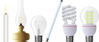
Classification of LEDs by their field of application
Initially, LEDs were used as indicators.
LED lighting elements differ in their area of application. The main types of LEDs: indicator and lighting. The devices are not the same; each has its own distinctive features and technical parameters.
Indicator LEDs
The first LED lamp appeared in the middle of the last century. The device had a dim reddish glow and low energy efficiency. Despite the shortcomings, developments in this direction were continued. After 20 years, options with yellow and green tints appeared. By the beginning of the 90s, the luminous flux reached 1 Lumen. By the early 2000s, the value reached 100 Lumens.
In 1993, Japanese engineers introduced a blue LED. The light of the device has become much brighter than its predecessors. From that moment on, devices with different luminescence began to appear on the market - a combination of blue, green, yellow and red allows you to create any color and shade.
Development is currently ongoing. New types of LEDs are emerging. At the same time, low-voltage consumption is maintained while the luminous flux increases.
Lighting LEDs
The first low luminosity IP (DIP) models were suitable for indicator work (for example, a switch is visible in the dark - a small red LED is lit). Modern devices make it possible to illuminate large areas - domestic and industrial premises. The power of the LED has increased - an LED device for a flashlight with an indicator of 3W is similar to an incandescent lamp of 25-30W. Electricity consumption is approximately 10 times less.
Such LEDs are called lighting due to their main area of application. Used in ribbons, headlights, lamps, and other products. They are manufactured in separate housings that allow surface mounting.
The main difference is that they produce only white light of cold or warm shades. Classification:
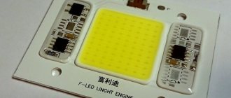
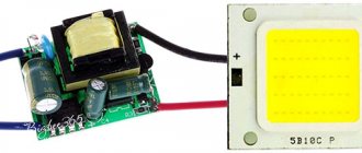
- SMD – models with a dispersive element of 100-130° are popular; substrate for the lamp is made of copper or aluminum, does not heat up;
- SOWs are more powerful, super-bright, consist of many small crystals, the scattering angle is significant;
- Filament - have the lowest efficiency (compared to SMD), are often used as decorative elements, and are manufactured in various sizes and shapes.
Based on the purpose and parameters of the room, the best option is selected. The characteristics of lighting devices are indicated on the packaging and in the technical documentation.
Crystal size
In the general characteristics of light-emitting diodes, you can find the value of the crystal size. This value is measured in Mils (mil), 1 mil corresponds to 0.0254 mm. Standard die square sizes are 24x24, 24x40, 35x35 and 40x40 mil. It is believed that the larger its area, the greater the power consumption, while heating during operation decreases and the overload limit increases. By comparison, 40x40mil measures 1.143x1.143mm and consumes about 1W.
Naturally, the material used for manufacturing and the conditions under which the crystal was grown are of great importance. The quality of calibration also matters. This means that it is cheaper to purchase LEDs from well-known brands; the performance of many Chinese LED light sources is overestimated.
Advantages and disadvantages
More and more users are seeking to replace outdated incandescent lamps with modern models of LED lamps. The main advantages of using LEDs:
- saving energy without compromising the luminous flux of the lamp;
- durable materials of the body and internal elements: low probability of mechanical damage;
- long service life: several times higher than that of Ilyich bulbs;
- size: diodes are compact and quite mobile;
- high brightness;
- safety: minimum network voltage – 3-24V.
Disadvantages include high cost and the need for constant voltage. The price of products is gradually decreasing due to high consumer demand.
Study
- St. Petersburg metro
From the many stations we chose: Sadovaya, Sennaya Ploshchad and the Technological Institute station.
Sadovaya station is illuminated with t5 fluorescent lamps (color temperature 3000k), the illumination in the lobby is ~ 150 lux - we look carefully at the marble/granite, the textures on it are clearly visible, thin veins are visible.
example of measuring brightness with a smartphoneNow we move to the Sennaya Ploshchad station, the bright light begins to “hurt” the eyes (color temperature ~4000k), illumination > 360 lux - we look at the floor and walls, the contrast pattern is clearly visible, but small details and halftones merge, and you have to strain your eyes when This gives the surface a lot of glare.
Technological Institute station (as of December 8, 2021) - illuminated by MGL lamps (of varying degrees of “fatigue”), illumination ~200 lux - the pattern and small veins on the marble/granite are very clearly visible, the detail is higher than when illuminated by fluorescent lamps.
- Home experiment
To experiment at home, you will need an incandescent lamp, I highly recommend using low-voltage halogen lamps, a thick spiral and rated voltage will give a more pleasant spectrum, with a lot of violet and green in the spectrum, it is better to use warm LED lamps, you can also add a high-quality fluorescent lamp for comparison.
The essence of the experiment is extremely simple: create illumination of 200 lux and 800 lux, see how small objects and complex textures look under this light. This effect will increase over time. This experiment is best done in the evening, when the sun has already set below the horizon.
Main characteristics
Characteristics of LEDs
Technical parameters of LEDs differ depending on the model. General indicators are:
- current consumption;
- nominal voltage (product voltage);
- power of consumed electricity (volt-ampere diagram);
- glow temperature;
- luminosity (level of luminous flux).
There are other characteristics, but they are used in rare cases. For domestic use, it is enough to take into account only these LED parameters.
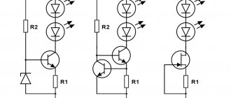
LED current consumption
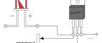
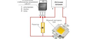
The indicator allows you to find out the amount of current consumed electrically by a device (LED). For devices with one active crystal, a value of 0.02A is sufficient. If the quantity is greater, the characteristic increases by a multiple of the number of elements. Based on this parameter, a resistor (stabilizer) is selected, which is installed at the input.
The stabilizer allows you to keep the device in working condition during voltage drops, regardless of the reason. Moreover, fluctuations in the LED current change the color temperature of the light from warm to brighter, cooler. If the voltage surge is significant, without an additional resistor the diode will burn out instantly.
To choose the right stabilizer for current conversion, you can use a special online calculator.
Rated voltage
The magnitude of the voltage is the amount of current in the conductor at the output. For the manufacture of LEDs, different materials are used, the electrical characteristics of which directly affect the level of permissible voltage and the color of the lighting. Thanks to this dependence, you can find out what voltage specific LEDs are designed for, even “by eye”. For example, if the glow is yellow or red, the voltage is in the range of 1.9-2.5 Volts, blue - about 3 Volts.
The current and voltage indicators of the LED must match. Otherwise, the diodes will either burn out quickly or will not produce light at the declared level.
To find out how many volts an LED is, you can use a multimeter or determine by the color of the glow. For the first method, you will need a multimeter and a resistor - the value will appear on the display after assembly.
Light diode resistance
The final resistance depends on the electrical circuit into which the element is connected. The same LED can show different values. For example, at the input - about 1 kOhm, at the output - several MOhms. However, resistance is not a linear characteristic. The indicator is inversely proportional to the voltage supplied to the mains. The higher the LED supply voltage, the lower the resistance level of the device.
Light output and beam angle
Comparing the light output of different lamps is quite difficult. For example, a 5 mm LED produces 1-5 Lm of light, and a 70 W incandescent lamp produces 750 Lm. The dispersion angle is selected based on the area of the room. In the corridor, a 30° diode is enough; in a room it is better to use elements of 90-120° or several at the same time. The maximum angle of LED lamps is 120°. The most illuminated place is the center; light scatters towards the periphery.
Luminous angle
LED lamp power
The diode power depends on several related indicators. For LEDs, the value ranges from 0.5 to 3 W. It is calculated according to Ohm's law: it is necessary to multiply the values of current and voltage. The current-voltage characteristic (volt-ampere characteristic) of the LED is also determined.
The choice of power supply for the device depends on the power level and current-voltage characteristics of the LED. It is not allowed to use inappropriate elements - the lamps will burn out if the voltage and current supply are excessive.
Colorful temperature
This indicator is similar to the characteristics of other lighting devices, especially LED fluorescent devices. The temperature of the LED is indicated in K (Kelvins); sometimes on the packages there is a corresponding diagram - a scale on which the range is indicated in color. Matching light and meaning:
- 2700-3000 – warm, yellowish;
- 3500-4000 – daytime, neutral;
- 5500-7000 – cold, with blue.
The main shades are presented. In practice there are much more colors. The temperature is selected based on the purpose of the room, the required level of comfort and user preferences. For example, it is recommended to install lamps with warm light in the bedroom, and with a natural shade in rooms without windows.
LED element chip size
When purchasing, you can find out the chip size only from the information on the packaging. You will not be able to independently verify the correctness of the specified data. Average device sizes: 45×45 ml, 24×40 ml and 24×24 ml for 1W, 0.75W and 0.5W, respectively. In the usual measurement system, 30x30 ml is equal to 0.76x0.76 mm. Due to its small size, you can find out the exact dimensions by disassembling the device completely.
The number of chips (crystals) varies, depending on the model and type of LED. In color elements (RGB), which do not contain a phosphor coating, their number can be counted.
Preparing for the study
Actually, let’s return to the title of this article “LEDs - blinding darkness”, this is the most complete description of the effect that was discovered. I want to say right away that this applies only to regions with low insolation and the autumn-winter-spring season.
With the massive transition to LEDs, in grocery stores it has become difficult to distinguish unwashed green potatoes from normal ones. But the understanding of what was wrong came precisely in the metro, where they began to switch en masse to LED lighting, and the floors and walls were lined with marble or granite .
Let me give you a few measurements taken “quickly” in the subway. I did not use a specialized lux meter, but limited myself to the Physics Toolbox Sensor Suite smartphone software, this software on my Xperia 1ii smartphone gives an error of about 15% in the measurement (when compared with the Radex Lupin lux meter), the maximum brightness level is 20000 lux, but since it is important for the experiment The difference is in brightness, not accuracy, then this application is sufficient.
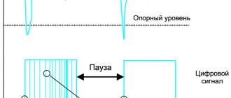
Unfortunately, the camera sees the world differently , so you won’t be able to capture this effect . Don’t forget about the inertia of vision and adaptation to lighting; the ideal option is to be under a light source for at least 15 minutes.
The measurements were carried out “by hand”, so the amount of light falling on objects and reflected from them is not examined, but in this case this does not affect the results. The essence of the experiment is to prove that at the same illumination <500 lux with LED lighting the detail is lower.
Checking an LED with a Multimeter
Checking LEDs with a multimeter
A multimeter is a special tester for electrical products that combines the functions of different devices. On the external panel there is a switch and several positions, one of them is for checking the LEDs. Procedure:
- Turn on the device and set the desired mode.
- Use special probes to touch the “legs” of the LED (outgoing wires).
- If the number 1 appears on the screen, change the polarity and repeat the touch with the probes.
- If there is sound and the diode starts to light up, everything is fine; if not, the LED is not working.
When it is known that the LED lamp is working, but the multimeter shows something else, you need to check the correct assembly of the circuit: the position of the tester, the connection of the contacts. If in this case the multimeter shows a malfunction, the resistor has failed.
Terminology in Russian
Serial connection of radio components is when the parts are connected to each other on only one side, i.e. sequentially:
Parallel connection of radio components is when the parts are connected to each other at two points - at the beginning and at the end.
Voltage is the force with which electricity is “pushed” into a wire to create its current. It is similar to the pressure difference at the beginning and end of the pipeline, depending on the force of the pump driving water into the pipe. Measured in volts (V).
Current is the “amount of electricity” passing through a wire per unit time. Similar to the amount of water passing through a pipe. Measured in Amperes (A).
Resistance is the force that prevents the passage of electricity. Similar to a narrowing of a pipe that prevents the free flow of water. Measured in ohms (ohms).
Power is a characteristic that reflects the ability, for example, of a resistor to pass electric current without harm to itself (overheating or destruction). Similar to the thickness of the walls of the narrowing area of the pipe.
Direct current is when electricity flows constantly in one direction, from plus to minus. These are batteries, accumulators, current after rectifiers. It is similar to the flow of water driven by a pump through a looped pipe in one direction.
Voltage drop is the potential difference before and after a part that provides resistance to electric current, that is, the voltage measured at the contacts of this part. Similar to the difference in pressure of water driven by a pump in a circle, before and after one of the narrowings of the pipe.
Alternating current is when electricity flows forward and backward, reversing the direction of movement at a certain frequency, for example, 50 times per second. This is an electrical lighting network, sockets. In them, one wire (zero) is common, relative to which in the other wire (phase) the voltage is either positive or negative. As a result, when you plug in, for example, an electric kettle, the current flows in one direction or the other. It is similar to the movement of water, which the pump, through a pipe (phase) lowered from above, either squeezes into the tank (zero) or sucks out of it.
AC frequency is the number of complete cycles (periods) of changing the direction of current (back and forth) per second. Measured in hertz (Hz). One period per second is equal to a frequency of 1 hertz. Alternating current has forward and reverse (i.e. positive and negative) half-cycles. In Russian household electrical networks (in sockets and light bulbs) the frequency is 50 hertz.
[Return to top]
Color coding of light diodes
On the one hand, color marking allows you to determine the type and characteristics of the LED, on the other hand, there are no uniform designations. Each manufacturer uses its own values. In Russia there is color coding, but it is rarely used - the list of elements consisting of numbers and letters is too large, it is quite difficult to remember, and decoding is inconvenient for the average buyer.
A simpler letter designation is accepted as generally accepted (unofficially). Mainly used for LED strips. In addition to the general characteristics, the degree of protection of the element from the penetration of debris and moisture is indicated - IP and numbers from 0 to 6.
To choose a good option for replacing outdated light bulbs, you need to find out what kind of LEDs there are and set the parameters of the connected electrical network: voltage, current, resistance.
You can’t focus on cost - brands of cheap LEDs often have inflated parameters and use unstable materials.
What's next
For fans of LED lighting disappointed by this article, I can only recommend SORAA VIVID, costing >2000 rubles for 470 lumens, which corrects some of the problems of LED lighting at the cost of reducing light output to <50 lumens per watt, but the problem of rapid degradation of the phosphor remains, and for those who wants to get truly comfortable lighting, I suggest you wait a little .
Soon -
Usage
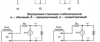
Semiconductor diode, a two-electrode electronic device based on a semiconductor (SC) crystal. The concept of "P. d." combines various devices with different principles of operation, having a variety of purposes. The classification system for semiconductor devices corresponds to the general classification system for semiconductor devices. The most common class of electrical transformer diodes includes: rectifier diodes, pulse diodes, zener diodes, and microwave diodes (including video detectors, mixing detectors, parametric detectors, amplifier and generator diodes, multipliers, and switching detectors). Among optoelectronic devices, photodiodes, light-emitting diodes, and PP quantum generators are distinguished.
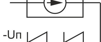
The most numerous are PDs, the action of which is based on the use of the properties of the electron-hole transition (p-n junction). If a voltage is applied to the p-n junction of the diode (Fig. 1) in the forward direction (the so-called forward bias), i.e., a positive potential is applied to its p-region, then the potential barrier corresponding to the junction decreases and begins intense injection of holes from the p-region into the n-region and electrons from the n-region into the p-region - a large forward current flows (Fig. 2). If a voltage is applied in the opposite direction (reverse bias), the potential barrier rises and only a very small minority carrier current flows through the pn junction (reverse current). In Fig. Figure 3 shows an equivalent circuit of such a P.D.
The operation of rectifier (power) diodes is based on the sharp asymmetry of the current-voltage characteristic (VC). For rectifier devices and other high-current electrical circuits, rectifier power supply units are produced that have a permissible rectified current Iv of up to 300 A and a maximum permissible reverse voltage U*rev from 20-30 V to 1-2 kV. Pds of similar application for low-current circuits have Iв < 0.1 a and are called universal.
At voltages exceeding U*o6p, the current increases sharply, and an irreversible (thermal) breakdown of the p-n junction occurs, leading to the failure of the p-n junction. In order to increase U*rev to several tens of kV, rectifier columns are used, in which several identical rectifier P.D. are connected in series and mounted in a common plastic housing. The inertia of rectifier diodes, due to the fact that the lifetime of the injected holes is > 10-5-10-4 sec, limits the frequency limit of their use (usually to the frequency range 50-2000 Hz). The use of special technological methods (mainly the doping of germanium and silicon with gold) made it possible to reduce the switching time to 10–7–10–10 sec and to create high-speed pulsed pulse generators, which are used, along with diode matrices, mainly in low-current signal circuits of computers.
It will be interesting A few facts about the laser diode
If you don't have the required resistor
The required resistance (R) and power (P) of the resistor can be obtained by combining resistors of other ratings and powers in series-parallel order.
Resistance formula for series connection of resistors
R = R1 + R2
Resistance formula for parallel connection of resistors
two:
R = (R1 * R2) / (R1 + R2) or R = 1 / (1 / R1 + 1 / R2)
unlimited quantity:
R = 1 / (1 / R1 + 1 / R2 + … + 1 / Rn)
Resistor power
The powers of the resistors in the assembly are calculated based on the same formulas as single resistors. When connected in series, the power supply voltage is substituted into the power calculation formula minus the voltage drop across other series resistors and the LED. This will be shown in more detail in the following examples.
Examples
1. Replace the 1.3 kOhm 0.125 W resistor from the first example with a series assembly.
1.3 kOhm = 1 kOhm + 100 Ohm + 100 Ohm + 100 Ohm
Let's calculate the minimum power for each resistor. To do this, let's calculate the actual voltage drop across each resistor, for which we first calculate the actual current, because it will differ from the nominal LED 0.01 A due to the reliability coefficient and the corresponding increase in resistance. So,
I = U / (Rres. + RLED), where
RLED = Upnom. / Inom. = 2 / 0.01 = 200 Ohm, which means the current in the circuit will be:
I = 12 / (1300 + 200) = 0.008 A
Now we calculate the actual voltage drop across the resistors and LED:
Updrop.res_1000 = Rres_1000 * I = 1000 * 0.008 = 8 V
Updrop.res_100 = Rres_100 * I = 100 * 0.008 = 0.8 V
Updrop of LED = RLED * I = 200 * 0.008 = 1.6 V
Now we have all the data to calculate capacity:
Pres_1000 = (12 −(0.8 + 0.8 + 0.8 + 1.6))2 / 1000 = 0.064 W
Pres_100 = (12 −(8 + 0.8 + 0.8 + 1.6))2 / 100 ≈ 0.0064 W
In total, based on the standard resistor powers, we get 1 kOhm 0.125 W and 3 100 Ohm resistors 0.05 W each. By connecting resistors of the indicated value in series, we get a total resistance of 1.3 kOhm of the power we need.
2. Replace the 39 kOhm 2 W resistor from the second example with a parallel assembly.
Entering the formula R = 1 / (1 / R1 + 1 / R2 + 1 / R3) into Excel, we find out that 41.2 kOhm ≈ parallel connection of 100 kOhm, 130 kOhm and 150 kOhm. More precisely, it will be a resistance of 41053 Ohms.
Let's calculate the minimum power for each resistor. To do this, let's calculate the actual voltage drop across each resistor, for which we first calculate the actual current, because it will differ from the nominal LED 0.01 A due to the reliability coefficient and the corresponding increase in resistance. So,
I = U / (Rres. + RLED), where
RLED = Upnom. / Inom. = 2 / 0.01 = 200 Ohm, which means the current in the circuit will be:
I = 220 / (41053 + 200) ≈ 0.005 A
Now we calculate the actual voltage drop across the LED:
Up LED = R LED * I = 200 * 0.005 = 1 V
Now we have all the data to calculate capacity:
Pres_68 = (220 −1)2 / 100000 ≈ 0.48 W
Pres_100 = (220 –1)2 / 130000 ≈ 0.37 W
Pres_110 = (220 –1)2 / 150000 ≈ 0.32 W
In total, based on the standard resistor powers, we get all resistors of 0.5 W each. By connecting resistors of the specified value in parallel, we get a total resistance of 41 kOhm of the power we need.
The above parallel and sequential methods can be combined, easily creating the following assemblies, which are also easy to calculate when split into fragments:
[Return to top]
Principle of operation
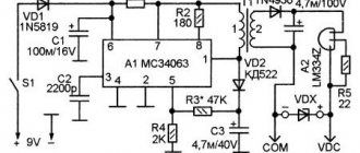
The easiest way to explain the principle of operation of rectifier diodes is with an example. To do this, we simulate the circuit of a simple half-wave rectifier (see 1 in Fig. 6), in which power comes from an alternating current source with voltage UIN (graph 2) and goes through VD to the load R.
Rice. 6. Operating principle of a single-diode rectifier
During the positive half-cycle, the diode is in the open position and passes current through it to the load. When the turn of the negative half-cycle comes, the device is locked and no power is supplied to the load. That is, there is a kind of cutting off of the negative half-wave (in fact, this is not entirely true, since during this process there is always a reverse current, its value is determined by the Irev characteristic).
As a result, as can be seen from graph (3), at the output we receive pulses consisting of positive half-cycles, that is, direct current. This is the principle of operation of rectifying semiconductor elements.
The disadvantages of a single-diode rectifier include:
- Low level of efficiency, since negative half-cycles are cut off, the efficiency of the device does not exceed 50%.
- The output voltage is approximately half that of the input.
- High noise level, which manifests itself in the form of a characteristic hum at the frequency of the supply network. Its reason is asymmetrical demagnetization of the step-down transformer (in fact, this is why for such circuits it is better to use a damping capacitor, which also has its negative sides).
Note that these disadvantages can be somewhat reduced; to do this, it is enough to make a simple filter based on a high-capacity electrolyte (1 in Fig. 7).
Rice. 7. Even a simple filter can significantly reduce ripple
The operating principle of such a filter is quite simple. The electrolyte is charged during the positive half-cycle and discharged when the negative half-cycle occurs. The capacitance must be sufficient to maintain the voltage across the load. In this case, the pulses will be somewhat smoothed out, approximately as shown in graph (2).
The above solution will improve the situation somewhat, but not much; if you power, for example, active computer speakers from such a half-wave rectifier, a characteristic background will be heard in them. To fix the problem, a more radical solution will be required, namely a diode bridge. Let's look at the operating principle of this circuit.
PN junction
Let us consider the processes occurring when current passes through an electron-hole junction
. The left layer, designated n, has electronic conductivity. The current in it is associated with the movement of free electrons, which are conventionally indicated by circles with a minus sign. The right layer, designated p, has hole conductivity. The current in this layer is associated with the movement of holes, which are indicated in the figure by circles with a “plus”.
Movement of electrons and holes in direct conduction mode
Movement of electrons and holes in reverse conduction mode.
When semiconductors with different types of conductivity come into contact, electrons due to diffusion
will begin to move to the p-region, and holes - to the n-region, as a result of which the boundary layer of the n-region becomes positively charged, and the boundary layer of the p-region - negatively. An electric field arises between the regions, which acts as a barrier for the main current carriers, due to which a region with a reduced charge concentration is formed in the pn junction. The electric field in a pn junction is called a potential barrier, and the pn junction is called a blocking layer. If the direction of the external electric field is opposite to the direction of the field of the pn junction (“+” in the p-region, “-” in the n-region), then the potential barrier decreases, the concentration of charges in the pn junction increases, the width and, therefore, the resistance of the junction decreases. When the source polarity changes, the external electric field coincides with the direction of the pn junction field, the width and resistance of the junction increases. Therefore, the pn junction has gate properties.