A significant danger for complete switchgear (SGD) with a voltage of 6–10 kV is posed by internal short circuits (SC), accompanied by an electric arc (EA). This problem is aggravated by the fact that many switchgear are not equipped with full-fledged high-speed protection against arc faults or the protection used in them does not meet modern requirements. This prompted RAO UES of Russia to issue a number of orders to improve the reliability of power facilities equipped with switchgear, providing for their equipping with high-speed protection against internal arc faults.
Currently, a number of domestic and foreign developers and manufacturers offer technical solutions for protection against arc short circuits for electric power and industrial enterprises, which mainly implement control of current parameters and luminous flux. The article brought to the attention of readers is based on the author’s own experience in the development and implementation of optical-electric arc protection. According to Vladimir Nagai, this experience allows us to make a number of proposals that may be debatable. We invite experts to discuss this topic.
Methods for recognizing arc faults
An arc fault is accompanied by both a change in the parameters and characteristics of the electrical network (current, voltage, resistance) and a significant increase in temperature, pressure, electrical conductivity and thermal (light) radiation inside the switchgear compartments. These information features can be used in protection, which must meet the following properties: high performance, absolute selectivity and high sensitivity. There are two main types of arc fault recognition methods:
- Methods based on monitoring the parameters and characteristics of an electrical circuit with an arc: the spectral composition of current or voltage, modules and arguments of phase and symmetrical components of currents and voltages, levels of current or voltage asymmetry, resistance or current-voltage characteristics of a short-circuited circuit. These methods allow you to use signals traditional for relay protection - currents and voltages. Along with the well-known advantages in converting and processing currents and voltages, there are also a number of disadvantages, namely that these symptoms can be observed not only during internal arc faults, but also during external faults. The latter makes it difficult to recognize internal damage, i.e. does not allow protection with absolute selectivity. However, studies performed, for example [1], show the possibility of information improvement of arc protection and, as a consequence, increasing the recognition of the modes under consideration, which will be discussed separately.
- Methods based on monitoring the parameters of the electric arc and its accompanying phenomena: temperature, pressure, electrical conductivity of the environment (degree of ionization of gases), radiation, optical properties of the environment, electromagnetic radiation. They make it possible to increase the degree of recognition of arc faults in switchgear. The influence of operating modes on the functioning of protections that implement control methods of this group, taking into account the design features of the switchgear, is minimal.
Comparison of protection methods against arc faults
A fairly simple technical solution for protection against arc faults is the use of maximum current protection (MCP), the positive qualities of which are simplicity, high elemental reliability and low cost. The limiting factors in the use of MTZ are relative selectivity and insufficiently high performance due to the need to coordinate with the protection of adjacent elements.
The requirement for absolute selectivity is met by current differential protection and “logical bus protection” (LBP) sections (based on overcurrent-permissive input and overcurrent-blocking outgoing connections), the coverage area of which includes busbars and circuit breakers. The “dead” zone of these protections is the compartments of instrument current transformers (CTs) and cable terminations - one of the most likely places of damage. The LZSh may fail in the initial period of a short circuit in the presence of recharge from powerful electric motors, which can be eliminated by controlling the direction of power at these connections. The appearance of higher harmonic components in voltages due to the nonlinearity of the current-voltage characteristic of the arc can be an additional information sign, as well as the presence of symmetrical components of the reverse and zero sequence of currents and voltages due to the inequality of the lengths of the arc columns and the contact of grounded metal structures.
Control of electric arc parameters
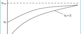
A significant part of the energy supplied to the electric arc column is converted into thermal energy. Contact and remote methods can be used to control the temperature in the cell, but their use is limited due to the relative complexity of the equipment used and the need for precise positioning of the temperature sensor in relation to the arc column, the position of which is unknown in advance. An increase in pressure, depending on the energy of the arc fault, the material of the busbar, the filling factor of the compartment, and the duration of the fault, can also be one of the signs of the type of damage under consideration. However, due to the leakage of the switchgear compartments, the sensitivity of the protections that control the pressure increase is also limited. For example, valve protections operate stably only at currents of more than 3.5 kA and higher [2].
Monitoring the density of charged particles (electrical conductivity) is possible only at distances close to the arc column, and when the electrical conductivity sensors move away from the arc column, the sensitivity of the protection sharply decreases. The power of thermal radiation, including light radiation, depends on the magnitude of the short-circuit current, the value of which is influenced by the resistance of the upstream system and the resistance of the arc column. An assessment of the sensitivity of protections [3] using optical information sensors shows that their sensitivity is sufficient for almost all types of switchgear connected to transformers with a power of 2.5 MVA and higher.
Modern technical implementation of protective devices
To protect switchgear, devices are currently used that respond to:
- to increase the pressure at the front of the shock wave at the initial moment of the arc fault (valve arc protection [2]);
- to increase the degree of ionization of gases in the channel of the arc column (antenna-type protection with an arc-catching electrode installed in the busbar compartments [2]);
- for the appearance of radiation from the arc column (protection using photothyristors, photoresistors, phototransistors and photodiodes [4–12], with fiber-optic sensors (FOS) [13–15]).
A comparison of methods for constructing switchgear arc protection shows that the most promising method from the point of view of obtaining maximum performance with absolute selectivity and a minimum number of information signs is the method of controlling illumination (luminous flux) inside the compartments [1].
Construction of optical-electric arc protection
Optical-electric arc protection can be divided into two groups according to the type of sensors used: with semiconductor photosensors and with FOD. The type of sensor determines not only the information processing algorithms, but also the implementation of protections, which can be classified as individual and centralized.
Centralized protections, as a rule, are designed to protect a section or group of cells and do not provide selective detection of the damage zone. Optical sensors, such as semiconductor photodevices, are connected in parallel, and the FOD is connected in a loop.
Individual design of protection allows you to influence the circuit breaker of a damaged cell, ensure selectivity of the protection action and identify the damaged area.
To increase selectivity, centralized protection can be implemented on a centralized-individual basis, when each sensor has its own observation zone and is assigned a specific number (“name”) [8,13,15]. When implementing individual protection using VODs, they are performed in the form of radial lines connected to the central information processing unit (CPI) [13,15]. When implementing sensors based on traditional photographic devices, they must also be made in the form of radial lines or connected in parallel, with the transmission of encoded information to the central unit [8].
The operating current system also significantly influences the implementation of protection. These features manifest themselves at substations where there is no operational direct current, which necessitates powering arc protection devices from alternating voltage or alternating current circuits [7–9]. In the first case, this requires the use of energy storage devices that provide protection when the voltage decreases during a short circuit. However, when the input switch is turned on during a short circuit when there is no voltage on the busbars, this can lead to protection failure. Therefore, it is more preferable to make power supplies of such protection from a combined power supply connected to alternating voltage circuits and alternating current circuits (for example, to circuits of measuring current transformers).
To increase operational reliability, almost all protections monitor, in addition to the luminous flux, at least one more feature characterizing an arc fault - current or voltage. This is also the purpose of adapting the arc protection measuring elements to the mode of the protected electrical installation and the presence of a braking channel, which is especially important for switchgear of old structures located inside buildings (closed switchgears) and having a semi-open type.
During an arc short circuit in an adjacent cell, it is possible to illuminate the photo sensors of the protected cell as a result of multiple reflections of the light flux. The orientation of the brake sensors towards the adjacent cell eliminates the non-selective effect of protection. The response speed of the protections in question is a few to tens of milliseconds. In this case, the total shutdown time of the switchgear, taking into account the action of the switch, should not exceed 0.1–0.15 s.
Individual protection devices are represented by devices of the RDZ type, developed at SRSTU, or the UDZ-1 type. At the same time, RDZ devices can also perform the functions of centralized protection when connecting photo sensors in parallel to each other.
Centralized devices are represented by the following types of protection: RDZ-018 (SURGTU), OSDZ (Energotekhnika), BSSDZ-01/02 (Promelektronika), OVOD (PROEL), REA-100 (ABB), PD-01 (ALSTOM) , FVIP (NIIIT). These devices differ both in the type of optical sensor used, communication lines between sensors and measuring elements, and in the element base. Basically, these protections are intended to protect one or two sections of switchgear and influence the switching devices of the supply connections. Therefore, as a rule, they do not “select” the damaged cell. The exceptions are protection types RDZ-018, OVOD, REA-100.
The first protection is implemented in the form of local information collection sensors located in protected cells and connected to the digital information center. The second protection implements the principle of radial fiber-optic lines going from the central information center to the protected cells. Protection type REA 100 also provides the ability to connect radial fiber optic lines, which also perform the functions of a sensor.
What advantages does breaker failure provide?
Initially, the breaker failure protection system, in the form of a panel with electromechanical relays, was used at substations and stations with switchgear of 220 kV and higher. Its use is due to increased reliability requirements for switching off a short circuit in the shortest period of time.
Imagine that on a 220 kV line, in accordance with the principle of short-range backup, sets of main (DFZ) and backup protections (DZ, TZNP, TO) are installed, and all this is useless due to a mechanical malfunction of the circuit breaker drive. The protections issued a shutdown signal, but nothing happens, and the line continues to “burn.”
The only hope left is for long-range backup protections, which are installed at opposite ends of adjacent lines.
At the request of long-range redundancy, these protections are required to sense short circuits on the adjacent line and eliminate them. But firstly, the time delays in this case can be quite long (especially if the DZ or TZNP begin to feel the short circuit only after some parallel lines are turned off). And secondly, long-range backup cannot always be ensured. In addition, when long-range backup protections operate, many switches are turned off at different substations, which complicates the work of the dispatcher when localizing an accident.
In such cases, measures are required to strengthen near-term redundancy, i.e. installation of a backup device in case of circuit breaker failure.
The breaker failure protection device receives a command to disconnect the circuit breaker from the protection, and if the shutdown does not occur after a period of time, the device gives a command to disconnect adjacent circuit breakers. Simple and reliable
In this case, the disconnection time from the breaker failure protection is always determined as the sum of the time of operation of the connection’s own protection plus the selectivity stage. In addition, the breaker protection system “uses” the sensitivity of its protection, which is higher than that of long-range backup protection.
At voltages of 110 kV and below, breaker failure protection was used less frequently due to the cost of the panel and the lack of strict requirements for shutdown speed, as at ultra-high voltage. After all, the breaker failure panel costs money and takes up space.
However, with the development of microprocessor technology, the breaker failure function has become practically free. The distributed breaker failure algorithm began to be used in the terminal logic, and only buses and input/output switches remained “outside”. Today, breaker failure protection is used at all voltage classes, starting from 6 kV.
Let's look at what a breaker failure failure gives at a standard substation according to the “6-1” scheme (one sectional 6 kV bus system).
1 case (remote fault on line 1)
If a short circuit occurs on line 1 in the coverage area of the overcurrent protection (end of the line), the protection is triggered with a time delay of 0.9 s. If the circuit breaker fails, the breaker failure algorithm will turn off the input circuit breakers after a time Tzash. = Tmtz + Turov = 0.9 + 0.3= 1.2 s.
If there is no breaker failure algorithm, then the input overcurrent protection will turn off the short circuit after 1.5 s (long-term redundancy).
Thus, we get a gain of 0.3 s.
Also note that here we use the overcurrent of the line, rather than the input, to run the algorithm, which gives significantly greater sensitivity. This difference will be especially strong for 6 kV sections with motors
Case 2 (close short circuit on line 1)
If a short circuit occurs on line 1 in the cutoff zone (beginning of the line), the protection is triggered with a time delay of 0.1 s. If the circuit breaker fails, the breaker failure algorithm will turn off the input circuit breakers after a time Tzash. = Tto + Turov = 0.1 + 0.3 = 0.4 s.
For long-distance reservation we will also get 1.5 s, i.e. now the gain is already 1.1 s.
It is obvious that at 6 kV the use of breaker failure provides an advantage in speed and sensitivity
With all its advantages, breaker failure protection is a rather “dangerous” function and must be used carefully. It should be remembered that when the breaker failure fails, it completely disconnects a section of the network, blocking any automatic power restoration, such as autoreclosers and automatic transfer switches. This means the impossibility of quickly restoring normal operation and a massive undersupply of electricity (especially if downstream consumers do not have their own automatic transfer switches).
In connection with this feature, when starting a breaker failure failure, in addition to monitoring the current through the switch, various methods are used to limit the possibility of excessive action.
We will talk about the logic and circuits of breaker failure protection in the next article
Ways to improve optical-electric arc protection
To select ways to further improve arc protection, it is of interest not only the opinion of the scientific community, developers and manufacturers of relay protection equipment, but also of specialists involved in the operation of electrical power equipment. Taking their opinion into account in many cases is decisive, especially in a market economy, when the choice of a particular technical solution remains with the consumer of the product. The author of this work carried out a survey of specialists from a number of energy systems of the Russian Federation on the problems of constructing arc protection, the results of which are given below (Fig. 1–6).
The majority of experts consider it acceptable to have a protection response time not exceeding 50 ms (51% of respondents), and only 21% consider it necessary to reduce the response time to 20 ms. A fifth of experts are ready to operate arc protection with a response time not exceeding half (14%) and a quarter (7%) of the industrial frequency period. Thus, the overwhelming majority of specialists prefer protections with moderate performance, which is explained by the well-known problems of noise immunity of ultra-high-speed protections and the problems of searching for damage after a shutdown, when it is sometimes difficult to find traces of damage.
The greatest difficulty (39%) was caused by the issue of assessing the sensitivity of the EDS, which is associated with insufficient awareness of specialists about the levels of illumination created by an electric arc in electrical installations with a voltage of 6–10 kV. Another part of the experts considers an acceptable sensitivity in the range of 100–1000 lx, which is associated with experience in operating photothyristor arc protection with a response threshold of 900–1000 lx and certain problems in testing it from incandescent lamps or from a photoflash. Reducing the lower limit of the response threshold makes it possible to simplify the ability to check and adjust the EDS from the specified sources.
As an additional controllable feature, most specialists (87%) prefer current control over voltage control (13%). Also, the overwhelming number of specialists (86%) give preference to a contact output organ, and only 7% of respondents agree to use an output organ such as a solid-state relay.
The widest range of opinions emerged regarding the choice of sensor type. Despite the fact that the issues of constructing optical-electric arc protection are discussed here, the author considered it his duty to include answers to other arc protection sensors. A quarter of the votes were received by fiber-optic sensors and more than half (57%) of the votes were received by traditional sensors based on photothyristor, photodiode and phototransistor. 7% of specialists are ready to use logical tire protection and protection based on pressure sensors. Only 4% of surveyed specialists prefer protection that controls conductivity in the bus compartment (antenna-type protection).
On the next question, the opinions of experts are divided almost equally: 46% give preference to fiber-optic communication lines and 54% to traditional electrical communication lines.
Trends in readiness for operation of the microprocessor element base (25%) were noted. However, the same part of specialists is ready to continue working with electromechanical equipment. The leading position is still occupied by microelectronic element base (45%).
The majority of specialists (61%) are in favor of disconnecting the supply connection (input switch or section switch) in the event of damage in any switchgear cell. A third of respondents prefer to turn off the circuit breaker of the damaged connection, despite the possibility of aggravating the accident.
Application
The devices are used at electrical substations of energy companies, gas, oil and other types of industries. In addition, ZDZ is used to protect traction substations on the railway and in the electrical equipment of the metro. The ideal conditions for arc protection to operate are unheated rooms.
Power company electrical substation
Arc protection is installed in complete switchgears (switchgear), which, due to their compact dimensions, can be turned off for a time not exceeding 1 second. Installation of the protective relay is carried out:
- in switchgear cells of indoor and outdoor installation;
- buses (conductors of electric current with low resistance);
- chambers of prefabricated one-way service (KSO);
- complete transformer substations (CTS) for industrial and auxiliary needs.
Construction of the EDZ
Arc protection of switchgear must be built taking into account its design features and types of switching devices. To do this, it is necessary to distinguish as special elements of the switchgear, which include input switch cells, sectional switch cells, special zones (compartments) of switchgear cells: bus bridge compartment, high-voltage switch compartments, voltage transformer, etc. This division of switchgear into zones will allow the most optimal impact on switching devices while minimizing the amount of damage. In the event of a short circuit in special elements, the section must be disconnected without a time delay, and in the case of a short circuit in special areas, for example, in the compartments of instrument current transformers, cable terminations and bushings, it is possible to disconnect only the damaged cell, for example, when using vacuum circuit breakers.
The burning of an arc in the cell of the input switch requires influence on the disconnection of not only the sectional switch, but also the switch from the higher voltage side of the power transformer. Damage to the sectional switch requires disconnection of the input switches. Taking into account the above, the protection must provide selective detection of arc short circuits in cells and their compartments.
There is also another approach to constructing switchgear arc protection, according to which any short circuit in the switchgear must be turned off by the input switch, which leads to “extinguishing” the section. This approach simplifies the implementation of protection and allows for the integration of sensors, for example, it allows the optical-electric sensor to be a single one, which is the case when using a fiber-optic line connected in a “loop”. When implementing protection according to the first option, it is possible to combine EDZ and devices that act on the same switches.
Mechanism and consequences of short circuit
When a short circuit occurs, accompanied by an electric arc, the temperature rises sharply in a matter of fractions of a second (up to 120,000C), damaging the walls of the cell and spreading to neighboring ones.
Note! In just moments, a cell in which a short circuit with an electric arc has been created burns out and cannot be repaired.
If measures are not taken in a timely manner, entire sections of the switchgear irreversibly fail with deep mechanical and thermal damage. Fires occur in electrical installations. A drop in voltage with an increase in current leads to braking and a decrease in the performance of electric motors, stopping parts of the electrical system, which leads to local and systemic (the most significant) accidents.
At the same time, the enterprise incurs large losses in the form of damage to expensive equipment, possible injuries to personnel, and unplanned downtime. The level of damage caused depends on the quality and type of insulating materials, the magnitude of the short circuit current and the duration of its impact.
A reasonable approach – in combination of protections
Thus, there is a trend in the readiness of switchgear manufacturers and operating organizations to use optical-electric arc protection that provides control of current and luminous flux. Previously, experts were more cautious about the use of such protections. At the same time, it can be noted that the capabilities of protections with control of currents and voltages are not fully used due to a limited set of information features in protections based on electromechanical and microelectronic element bases. The use of microprocessor technology eliminates the problem of the complexity of algorithms and the volume of processed information, which allows us to return to the issues of building high-speed and selective protection with traditional information sensors (current and voltage transformers).
At the same time, some of the disadvantages noted above can be turned into advantages, for example, by reducing the time of their installation and commissioning, because Unlike the installation of optical-electrical protection, it is not necessary to disconnect the entire section. The implementation of more advanced protection against ground faults, which ensures the detection of damage not only on cable or overhead lines, but also inside the switchgear, will prevent the development of phase-to-phase arc faults.
The proposed concept for constructing switchgear protections and lines extending from them may be the subject of additional discussion. A reasonable combination of EDS and protections with current and voltage control will improve the reliability of protection and ensure redundancy.
Vladimir Nagai, Doctor of Technical Sciences, Professor of the department. "Electric stations", deputy. Director of the Research Institute of Energy, South Russian State Technical University, Novocherkassk
LITERATURE
- Nagai V.I. Relay protection of branch substations of electrical networks. – Energoatomizdat, 2002. – 312 p.
- Zotov A.Ya. About arc protection of switchgear switchgear (N) cabinets 6–10 kV on “Crab” and “Antenna” sensors // Energetik. – 1997. – No. 3. – P. 17–18.
- Nagai V.I., Sarry S.V. Determination of the sensitivity of optical-electric protection against arc short circuits in complete switchgears with a voltage of 6–10 kV // Izv. universities Electromechanics. – 1999. – No. 1. – P. 48–51.
- Nagai V.I. Selection and technical implementation of high-speed switchgear protection against arc short circuits // Elektro. – 2002. – No. 1. – P. 35–39.
- Sereda N.N., Kharitonov V.V. Application of photothyristors to protect networks during arc short circuits // Materials of the seminar “New complete electrical devices”. – M.: Moscow House of Science and Technology. Propaganda, 1990. – pp. 53–57.
- IN AND. Nagai, S.V. Sarah, M.M. Kotlov et al. Optical-electric arc protection of KRUN 6–10 kV // Energetik. – 2000. – No. 8. – P. 38–39.
- Nagai V.I. Sarry S.V., Voitenko A.S. Relay protection of switchgear with control of luminous flux // Industrial energy. – 2001. – No. 11. – P. 32–36.
- Nagai V.I., Sarry S.V., Voitenko A.S. High-speed relay protection of switchgear from arc short circuits with optical-electric sensors // Electric stations. – 2002. – No. 3. – P. 55–59.
- Vainshtein V.L., Survillo B.A. Photo relay for protection against arc short circuits // Energetik. – 1989. – No. 11. – P. 27–31.
- 10. Sukhoruchkin I.V., Bocharov N.V. Arc fault protection relay // Electric stations. – 1990. – No. 5. – P. 89–91.
- Korotkov L.V., Pogodin N.V. High-speed optical arc protection system for indoor switching devices 6–10 kV // Relay protection and automation of power systems 2000: Abstract. report XIV scientific and technical conference. – M.: CDU UES of Russia, 2000. – P. 48–49.
- Krylov I.P. Device for high-speed selective light arc protection BSSDZ-01/02 // Collection of abstracts. report seminar-meeting of heads of relay protection and automation services of JSC-energo, heads of electrical laboratories of power plants, leading specialists of relay protection and automation systems of the UES of the North Caucasus, RAO UES of Russia, RP Yuzhenergotechnadzor. – Pyatigorsk, 2001. – P. 112–114.
- Kalachev Yu.N., Shevelev V.S. Arc protection device for 6–10 kV switchgear cells // Energetik. – 2001. – No. 1. – P. 25–26.
- Demyanovich M.V., Evreev A.I., Pimenov A.V. and others. New arc protection for complete switchgears // Energetik. – 2001. – No. 5 – P. 24.
- Grigoriev V.A., Milokhin V.E., Paley E.L. Fiber-optic arc protection of 6-10 kV switchgear cells // Energetik. – 2002. – No. 2. – P. 23–24.
The article was published in the journal “Electrical Engineering News” No. 5(23) 2003
Links
- High-speed arc protection switchgear
- Tire arc protection
- Arc protection. Improving the operating principle
- Arc protection selection
Complete switchgears (SGD) up to 35 kV are the most common elements of electrical substations, the advantage of which is their compact size, convenient installation and configuration. If a short circuit occurs inside these devices, the power outage time should not exceed 1 second. This is due to their small size. This problem is complicated by the fact that switchgear manufactured in the last century most often did not have arc protection installed.
Arc protection is also called arc fault protection (AFP). Recently, optical arc protection, abbreviated as (ODP), has been increasingly used. It is a type of short circuit protection, the principle of which is based on triggering when an arc flash occurs.
The most common are phase-to-phase faults, as well as ground faults.
These dangerous phenomena are usually accompanied by:
- Release of a significant amount of heat.
- Current surges.
- Voltage impulses.
- Transition processes.
Trigger conditions
- Increasing current. When an arc occurs, a short circuit usually occurs. This condition is called current control.
- Sensor triggered. Nowadays valve arc protection is often used. At the moment of closure, excess pressure builds up, as a result of which the metal lid that covers the high-voltage cell flies out and closes the valve contact. The closure of this contact and the presence of current control creates the conditions for the protection to operate.
- Recently, many substations have used modern optical arc protection. Here the sensors are no longer valves, but fiber-optic sensors that respond to a flash of light.
- Aging or damaged insulation.
- Violation of the connection diagram of cables and buses.
- Electrical fault.
- High humidity.
- Pollution.
- Corrosion.
- Increased tension.
- Maintenance personnel errors.
These causes can be prevented by good maintenance. Time is of the essence when identifying and mitigating the effects of arc faults. An arc lasting 0.5 seconds can severely damage the insulation, causing the switchgear cell to burn out completely.
Processes during closure
These processes depend on the time of exposure to the current and its magnitude. Short circuit current is characterized by a significant increase in temperature. The degree of damage depends on the wear rate of the equipment and the quality of the insulation.
When an arc fault occurs, the metal walls of the cell are burned through, and the fault can spread to neighboring cells. Also, with good tightness of modern equipment and the absence of safety valves, high pressure during closure destroys the equipment and the cell body, which contributes to the complete destruction of all elements of the cell.
The consequences of an arc fault in switchgear can be very serious. In this case, expensive equipment is damaged, resulting in downtime and the enterprise incurring economic losses. Also, the consequences may be injuries to operating personnel.
How does arc protection work?
The sensor of this protection is a device that reacts to an electric arc flash and transmits information to actuators that turn off the electricity to prevent negative consequences.
Arc Detection Methods
- Determination of the change in brightness of light caused by an electric arc.
- Comparison of the characteristics of the electrical circuit before and after the circuit.
- Comparison of pressure and temperature in the chamber of the switchgear before and after the circuit.
Bus fault protection
Organized in switchgears from 6 to 10 kilovolts to protect busbars, for devices with closed current-carrying elements. Protection works in two ways:
- Fixation of light flash.
- Mechanical action of the arc.
Fiber Optic Protection
Its operation is based on the principle of detecting an electric arc flash using special optical sensors. Such protections are placed in the input compartments, on the withdrawable element of the cells, in the cable compartments. Electric arc detection is carried out immediately in all protection elements. Cells are de-energized under the following conditions:
- Maximum protection start signal.
- Signals from all sensors.
Sensor types
- Distribution ones, covering several flash detection locations with one cable.
- With fastening at the end part, they make it possible to accurately detect the presence of an arc.
Advantages
- Immunity to electromagnetic interference.
- The use of insulating materials in sensor devices.
- High performance.
- Low cost of equipment, installation and configuration.
Photothyristor arc protection
Photothyristors are used as a sensitive element, responding to changes in light brightness.
Valve protection
The operation of this system is to use the processes that occur during an arc fault: increasing the pressure in the chamber. As a sensitive element, this arc protection includes special valves with switches that are installed in the switchgear chambers.
Membrane protection
The principle of operation is the ability of a membrane-type switch to respond to changes in air pressure from an electric arc. The components of this protection are membrane sensors, back pressure valves, and flexible pipelines.
Tubes are supplied to all cells of the distribution device, which are then combined into a common network and connected to the membrane sensor. When the pressure in any cell increases, the sensor is triggered and de-energizes the equipment.