Modern electrical equipment, as a rule, contains copper conductors, reliably protected by an insulating sheath. Electric motors used in industry and everyday life are no exception. But for the efficient operation of these units, it is important to ensure that the conductor insulation is maintained in perfect condition and retains its protective properties.
AC motors
1.8.15.
AC electric motors up to 1 kV are tested according to clauses 2, 4, 6, 10, 11. ¶ AC electric motors above 1 kV are tested according to clauses 1-4,7,9-11. 
According to clauses 5, 6, 8, electric motors that arrive for installation in disassembled form are tested. 
1. Determining the possibility of switching on electric motors with voltages above 1 kV without drying. Should be carried out in accordance with section. 3 “Electric machines” SNiP 3.05.06-85. “Electrical devices” of the State Construction Committee of Russia. 
2. Insulation resistance measurement. Permissible values of insulation resistance of electric motors with voltages above 1 kV must comply with the requirements of the instructions specified in paragraph 1. In other cases, the insulation resistance must comply with the standards given in table. 1.8.8. 
Table 1.8.8. Permissible insulation resistance of AC motors. 
Megger voltage, kV
Stator winding with voltage up to 1 kV
Not less than 0.5 MOhm at a temperature of 10-30 ° C
Rotor winding of a synchronous electric motor and an electric motor with a wound rotor
Not less than 0.2 MOhm at a temperature of 10-30 °C (not less than 2 kOhm at +75 °C or 20 kOhm at +20 °C for non-salient-pole rotors is allowed)
Bearings for synchronous electric motors with voltages above 1 kV
Not standardized (measurement is made relative to the foundation slab with fully assembled oil pipelines)
3. Power frequency high voltage test. Produced on a fully assembled electric motor. 
The stator winding is tested for each phase separately relative to the housing with the other two connected to the housing. For motors that do not have terminals for each phase separately, it is allowed to test the entire winding relative to the housing. 
The test voltage values are given in table. 1.8.9. The duration of application of the normalized test voltage is 1 min. 
4. DC resistance measurement: 
a) stator and rotor windings. Produced with electric motor power of 300 kW or more. 
The measured resistances of the windings of different phases should differ from each other or from the factory data by no more than 2%; 
b) rheostats and starting adjustment resistors. The total resistance is measured and the integrity of the taps is checked. The resistance value should differ from the passport data by no more than 10%. 
5. Measuring the gaps between the steel of the rotor and stator. The dimensions of the air gaps at diametrically opposite points or points shifted by 90° relative to the rotor axis should differ by no more than 10% of the average size. 
Table 1.8.9. Power frequency test voltage for AC motors. 
Test voltage, kV
Power up to 1 MW, rated voltage above 1 kV
Power above 1 MW, rated voltage up to 3.3 kV
Power above 1 MW, rated voltage above 3.3 to 6.6 kV
Power above 1 MW, rated voltage above 6.6 kV
Rotor winding of a synchronous electric motor
8Unom of the excitation system, but not less than 1.2
Rotor winding of an electric motor with a wound rotor
Rheostat and starting resistor
Synchronous motor field suppression resistor
6. Measuring clearances in plain bearings. The dimensions of the gaps are given in table. 1.8.10. 
7. Vibration measurement of electric motor bearings. The vibration values measured at each bearing must not exceed the values given below: 
Synchronous motor speed, Hz
Permissible vibration, µm
8. Measuring the rotor run-up in the axial direction. Produced for electric motors with plain bearings. The axial spread should not exceed 2-4 mm. 
9. Testing the air cooler with hydraulic pressure. Produced by excess hydraulic pressure of 0.2-0.25 MPa (2-2.5 kgf/cm 2 ). Test duration 10 min. In this case, there should be no decrease in pressure or leakage of the liquid used during the test. 
10. Checking the operation of the electric motor at idle or with the mechanism unloaded. Duration of inspection is at least 1 hour. 
11. Checking the operation of the electric motor under load. Produced at the load provided by the process equipment at the time of commissioning. In this case, for an electric motor with adjustable rotation speed, control limits are determined. 
Table 1.8.10. The largest permissible clearance in plain bearings of electric motors. 
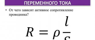
Electrical resistance, conductivity concept
All bodies that pass electric current through themselves can provide some resistance to this current. The inherent resistance of conductors to the passage of current through them is called electrical resistance.
The resistance of a metal to electricity is explained by the electron theory. Moving along a conductor, electrons constantly encounter atoms and other electrons. Their interaction with each other leads to the loss of a certain amount of energy from the electrons. They literally resist their movement. The resistance value of different conductors will be different. It all depends on their atomic structure.
The resistance to electric current that liquids and gases provide can be explained in the same way. The only difference is that in such materials and substances it is not electrons, but molecular particles that have a certain charge.
In calculations, resistance is usually denoted using the letters R (r).
The unit of electrical resistance in the International System of Units is Ohm.
Ohm is the resistance of a mercury column with a length of 106.3 cm and a cross section of 1 mm2 (assuming the temperature is 0 ° C).
Let's say the resistance provided by the conductor is 4 ohms. You need to write this down as follows: R = 4 Ohms; r = 4 Ohm.
To measure large electrical resistances, there is an official unit, the megaohm. 1 megaohm = 1000,000 ohms.
The greater the electrical resistance of a particular conductor, the worse the electric current passes through it. This rule also applies in the opposite direction. The less resistance a conductor has, the easier it is for current to pass through it.
Solution conductivity measurement
From this we can draw a logical conclusion: in terms of the ability of current to pass through a material, two interrelated quantities are considered: electrical resistance and electrical conductivity.
Electrical conductivity refers to the ability of a substance or material to pass current through itself.
Electrical conductivity is the reciprocal of electrical resistance. Therefore, it can be expressed as 1/R. It is usually designated using the letter g.
Measuring the insulation resistance of an electric motor
Insulation testing is carried out in different ways.
Megger insulation test
Resistance is measured using a mechanical or electronic megger.
Important! Checking the insulation of motors up to 380V is carried out with a 500-volt device, and from 0.4 to 1 kV with a 1000V device.
Before checking the insulation resistance, the electrical machine is inspected for damage to the housing. A wet electric motor must be dried before testing. It is advisable to disconnect all windings from each other to check the insulation between them.
How to determine power?
There are several ways to determine the power of an electric motor: by shaft diameter, by size and length, by current and resistance, by measuring with an electricity meter.
By overall dimensions
What dimensions need to be measured:
- Length, width, height of the case
- Distance from center of shaft to floor
- Shaft length and diameter
- Mounting dimensions for feet (flange)
By shaft diameter
Determining the power of an electric motor by shaft diameter is a common request for search engines. But this parameter is not enough to accurately determine - two engines of the same size, with the same shafts and rotation speed can have different power.
A table relating shaft diameters to power and speed for AIR and 4AM engines.
| Electric motor power P, kW | Shaft diameter, mm | |||
| 3000 rpm | 1500 rpm | 1000 rpm | 750 rpm | |
| 1,5 | 22 | 22 | 24 | 28 |
| 2,2 | 24 | 28 | 32 | |
| 3 | 24 | 32 | ||
| 4 | 28 | 28 | 38 | |
| 5,5 | 32 | 38 | ||
| 7,5 | 32 | 38 | 48 | |
| 11 | 38 | 48 | ||
| 15 | 42 | 48 | 55 | |
| 18,5 | 55 | 60 | ||
| 22 | 48 | 55 | 60 | |
| 30 | 65 | |||
| 37 | 55 | 60 | 65 | 75 |
| 45 | 75 | 75 | ||
| 55 | 65 | 80 | ||
| 75 | 65 | 75 | 80 | |
| 90 | 90 | |||
| 110 | 70 | 80 | 90 | |
| 132 | 100 | |||
| 160 | 75 | 90 | 100 | |
| 200 | ||||
| 250 | 85 | 100 | ||
| 315 | — |
According to the meter reading
Typically, meter measurements are displayed in kilowatts (hereinafter referred to as kW). For accurate measurements, you should turn off all electrical appliances or use a portable meter. The power of the electric motor is 2.2 kW, which means that it consumes 2.2 kW of electricity per hour.
To measure power using a meter reading you need:
- Connect the motor and let it run for 6 minutes.
- Multiply the meter measurements by 10 - we get the exact power of the electric motor.
Calculation of power by current
First you need to connect the motor to the network and measure the voltage readings. We measure the current consumption on each of the phase windings using an ammeter or multimeter. Next, we find the sum of the currents of the three phases and multiply them by the previously measured voltage indicators, clearly in the formula for calculating the power of the electric motor by current.
- P – electric motor power;
- U – voltage;
- Ia – 1st phase current;
- Ib – 2 phases;
- Ic – 3 phases.
Insulation resistance standards for electrical machines
The PUE (electrical installation rules) regulates the insulation resistance of electric motors depending on the design and power of the device.
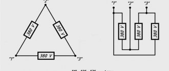
Permissible resistance when testing the insulation of asynchronous electric machines
When measuring the insulation of asynchronous motors, the star or delta connection of the stator windings must be disassembled and each coil must be checked relative to the housing and to each other. Tests are carried out at a machine temperature of 10-30°C.
The insulation resistance should be:
- in the stator no less than 0.5 mOhm;
- in a wound rotor no less than 0.2 mOhm;
- The minimum insulation resistance of temperature sensors is not standardized.
In order not to use the reference book, the usually acceptable resistance is considered to be 1 mOhm. Smaller values indicate minor violations that will eventually lead to failure of the electric machine.
Important! In order to avoid such a situation, it is advisable to send the device to a specialized enterprise for medium repairs.
DC Motor Insulation
To check the insulation in DC machines, it is necessary to remove the brushes from the brush holders or place insulating material under them.
The measurement is carried out between different parts of the electrical machine circuit:
- field windings and armature commutator;
- brush holder and device body;
- armature commutator and housing;
- field windings and electrical machine housing.
Important! If possible, the field winding coils are disconnected from each other and checked separately.
The minimum permissible insulation resistance depends on the temperature and rated voltage of the electrical machine. At 20°C it is:
In addition to the windings and armature, the resistance of the excitation and armature winding bands is measured. It is checked between the bandage itself and the body, as well as the winding secured by it. It should not be less than 0.5 mOhm.
Continuity test of an asynchronous motor
This type of electric motor is quite often used in household devices operating from a 220 V network. After dismantling the unit from the device and visual inspection, during which no short circuit is detected, diagnostics are carried out in the following sequence:
- Measure the resistance between the motor terminals. This operation can be carried out with a multimeter, which must be switched to resistance measurement mode up to 100 Ohms. A working asynchronous motor should have a resistance of about 30 - 50 Ohms between one extreme and middle terminal of the connected winding, and 15 - 20 Ohms between the other extreme and middle contacts. These measurements indicate complete serviceability of the starting and main windings of the unit.
- Diagnose current leakage to ground. To test the unit for electric current leaks, you need to switch the multimeter operating mode to the resistance measurement position of up to 2,000 kOhm and alternately connect each terminal to the motor housing to determine the presence or absence of insulation damage. In all cases, the multimeter display should not show any readings. If an analog device is used to measure leakage, the needle should not deviate during diagnostic procedures.
If deviations from the norm were identified during the measurement process, the unit must be disassembled for more detailed studies. The most common failure of asynchronous electric motors is an interturn short circuit.
With such a malfunction, the device overheats and does not develop full power, and if operation of the device is not stopped, the electrical unit can be completely damaged.
To test turn-to-turn short circuits, the multimeter is switched to resistance measurement mode up to 100 Ohms.
It is necessary to ring each stator circuit and compare the results obtained. If the resistance value in one of them differs significantly, then in this way it is possible to confidently diagnose an interturn short circuit in the winding of an asynchronous electric motor.
Reasons for low resistance
There are several reasons for low insulation resistance.
Electric machine overheating
This situation occurs due to an overload of the electric machine or a break in one of the phases in three-phase electric motors. It is impossible to eliminate this problem in a workshop and the device must be sent to a specialized enterprise to replace the windings.
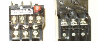
Protection devices help prevent such a malfunction:
- The thermal relay turns off the electric machine when overloaded;
- The voltage relay turns off the installation if one of the phases is missing or the network voltage is low.
Important! For better protection, temperature sensors are built inside electric motors. In new machines they are installed during manufacture, and in old machines such devices can be installed during planned or major repairs.
Tags
electric motor insulation resistance protected by an insulating sheath. to insulate conductors insulation resistance insulation resistance insulation resistance electric motor insulation resistance fire insulation and electric motor insulation resistance electric motor insulation resistance electric motor insulation in everyday life electric motors non-insulation of electric motors electric motor insulation for electric motors and electric motor windings follows electric motor insulation with megohmmeter electric motor insulation with electric motor elements. electric motor insulation with increased exciting circuits outputs and exciting windings and fixed motor windings .between the windings are carried out the residential winding of the motor winding breakdown on insulation resistance measurement insulation resistance test insulation resistance standards low resistance insulation resistance test insulation resistance insulation resistance measurement insulation resistance measurements insulation resistance standards insulation resistance measurements
megger test ground asynchronous
Design features of megaohmmeters
There are different models of megaohmmeters, but they all include a high-voltage DC source (generator) and an ammeter. The generator produces a calibrated voltage, the value of which is set in advance. For this reason, the measuring scale of the device can be immediately calibrated in units of resistance rather than current.
Types of megohmmeters
There are two main types of devices:
Megaohmmeters equipped with a mechanical generator. These are old-style devices that use dynamos as a voltage source. They must be actuated manually at a frequency of approximately 2 rps. They are quite large and heavy, but do not require a power source. Such devices are convenient due to their autonomy.
This is what a megohmmeter with a mechanical generator looks like
Megaohmmeters equipped with an electronic converter. These are new generation devices. In them, the constant voltage source is powered by built-in batteries or a power supply. Such devices are compact and lightweight, but their performance depends on the power source.
This is what an electronic megohmmeter looks like
Safety regulations
Before checking the engine, make sure that the plug and cord of the entire device are in good working order. If electric current flows into the device, the indicator light will light up. If everything is in order with the current supply, we proceed to check the motor, which must first be removed from the unit housing. This operation can only be performed when it is completely de-energized!
It would be a good idea to check the serviceability of the multimeter. Most often, the battery charge decreases, which is why the readings may be inaccurate.
Motor design
In order to quickly master how to check an electric motor, you need to clearly understand the structure of the main parts. HOW TO CHECK How to ring a three-phase motor with a tester. All motors are based on two parts of the structure: the rotor and the stator. The 1st component always rotates under the influence of the electric field, the 2nd component is motionless and just creates this vortex flow.
To understand how to check an electric motor, you will need to disassemble it at least once with your own hands. The design of different manufacturers is different, but the principle of diagnosing the electrical part remains constant. There is a gap between the rotor and stator, in which small iron shavings can accumulate when the housing is depressurized.
When bearings wear out, they can produce excessive current characteristics, as a result of which the protection will be knocked out. How to test a motor with a multimeter. When dealing with the question of how to check an electric motor, one should not forget about mechanical damage to the moving parts and the parts where the contacts are located.
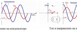
Device and principle of operation
Capacitance
A megohmmeter is a device for checking insulation resistance. There are two types of devices - electronic and pointer. Regardless of the type, any megohmmeter consists of:
- Constant voltage source.
- Current meter.
- Digital screen or measurement scale.
- Probes, through which voltage from the device is transmitted to the object being measured.
This is what a pointer megaohmmeter looks like (on the left) and an electronic one (on the right)
In pointer instruments, the voltage is generated by a dynamo built into the housing. It is driven by a meter - it rotates the handle of the device with a certain frequency (2 revolutions per second). Electronic models take power from the mains, but can also run on batteries.
The operation of the megohmmeter is based on Ohm's law: I=U/R. The device measures the current that flows between two connected objects (two cable cores, core-ground, etc.). Measurements are made with a calibrated voltage, the value of which is known; knowing the current and voltage, you can find the resistance: R=U/I, which is what the device does.
Approximate diagram of a magaohmmeter
Before testing, the probes are installed in the appropriate sockets on the device, and then connected to the object being measured. During testing, a high voltage is generated in the device, which is transmitted to the object being tested using probes. Measurement results are displayed in mega ohms (MΩ) on a scale or screen.
Checking other parts and other potential problems
- oil leak from the condenser;
- presence of holes in the body;
- swollen capacitor housing;
- unpleasant odors.
How to check resistance with a multimeter
The capacitor is also checked using an ohmmeter. The probes should touch the terminals of the capacitor, and the resistance level should be small at first, and then gradually increase as the capacitor is charged with voltage from the batteries. If the resistance does not increase or the capacitor is short-circuited, then most likely it is time to change it.
Before re-testing, the capacitor must be discharged.
We move on to the next stage of checking the engine: the rear part of the crankcase, where the bearings are installed. At this point, a series of electric motors are equipped with centrifugal switches that switch starting capacitors or circuits to determine the number of revolutions per minute. You also need to check the relay contacts for burnt marks. In addition, they should be cleaned of grease and dirt. The switch mechanism is checked using a screwdriver; the spring should work normally and freely.
And the final stage is checking the fan. We will look at this using the example of testing a TEFC engine fan, which is completely enclosed and air-cooled.
Make sure the fan is securely attached and not clogged with dirt or other debris. The holes on the metal grill must be sufficient for free air circulation; if this is not ensured, the engine may overheat and subsequently fail.
Brief theoretical information
| Heat resistance class | | A | E | IN | F | N | WITH |
| Limit temperature, С | 90 | 105 | 120 | 130 | 155 | 180 | 180 |
Thermometer method
| Engine parts | Maximum permissible temperature rises, С, for insulating materials of heat resistance class | Temperature measurement method | ||||
| A | E | B | F | H | ||
| AC windings of motors 5000 kVA and above or with a core length of 1 m or more | 60 | 70 | 80 | 100 | 125 | Resistance or temperature indicators placed in grooves |
| The same, but less than 5000 kVA or with a core length of less than 1 m | 50* | 65* | 70** | 85** | 105*** | Thermometer or resistance. The data is given for measurement using the thermometer method |
| Rod windings of asynchronous motor rotors | 65 | 80 | 90 | 110 | 135 | Thermometer or resistance |
| Slip rings | 60 | 70 | 80 | 90 | 110 | Thermometer or temperature indicators placed in grooves |
| Cores and other steel parts in contact with windings | 60 | 75 | 80 | 110 | 125 | Thermometer |
| The same, not in contact with the windings | The temperature rise of these parts must not exceed values that would create a risk of damage to insulating or other adjacent materials | |||||
| * – when measuring by the resistance method, the permissible temperature increases by 10 °C; ** – the same, by 15 °C; *** – the same, by 20 °C. |
Thermocouple method Resistance method Ammeter-voltmeter method
Methodological instructions A B B A A Work order
- Assemble the diagram fig. 2, making sure that the handle of the laboratory autotransformer is pulled out all the way.
- Install jumpers C2-C4 and C3-C5.
- Turn on the SF1 machine. at the same time, the HL signal lamp lights up, indicating the presence of voltage in the circuit.
- Set switch SA1 to position I.
- Using the LATR TV handle, set the voltage U1 on the voltmeter PV1, at which the readings of the ammeter PA1=I1 will not exceed 20% of the rated motor current.
- Set switch SA2 to position I and record the readings PV1=U1x and PA1=I1x.
- Calculate the ohmic resistance (Ohm) of the electric motor winding in a cold state: .
- Assuming that all phases have the same resistance, we determine the resistance (Ohm) of one phase of the winding based on their series connection: .
- Set switches SA1 and SA2 to position 0.
- Install jumper C1-C6.
- Turn on the SF2 machine.
- Use the handle of the load device to load the engine until the ammeter reading PA2 is equal to Inom. Continue heating the winding for 10...15 minutes, adjusting the constancy of the ammeter readings with a load device.
- Turn off the SF2 automatic and wait until the engine stops completely.
- Remove jumper C1-C6.
- Set SA1 and SA2 to position I, take readings PV1(U1Г) and PA1(I1Г) no later than 20 s after stopping the engine.
- Determine the resistance (Ohm) of the winding in the hot state: .
- Assuming that all windings are heated equally, and taking into account their series connection, determine the resistance (Ohm) of one phase: .
- Calculate the temperature rise of the windings over the temperature of the cooling medium, taking the temperature of the windings in a cold state equal to the ambient temperature.
Note.
gf
- Calculate the absolute temperature of the windings and draw a conclusion about the serviceability of the motor: Tabs = T + T.
- Prepare a work report.
Control questions
- What is the purpose of testing electric motor windings for heating?
- What is the essence of the thermometer method?
- What is the essence of the thermocouple method?
- What is the essence of the resistance method?
- How to measure the temperature of the cooling medium?
- What is the limit on the current passed through the motor windings during a heating test?
- What is heat resistance and what heat resistance insulation classes are most often used for electric motor windings?
Recommended reading
- Zyuzin A.F., Pokonov N.Z., Antonov M.V. Installation, operation and repair of electrical equipment of industrial enterprises and installations. - M.: Higher School, 1986.
- Handbook for setting up electrical installations. - M.: Energy, 1976.
- Slonim N.M. Testing of asynchronous motors during repairs. - M.: Energy, 1980.
- Tretyakov M.N. Testing low power electric motors. - M.: Energy, 1966.
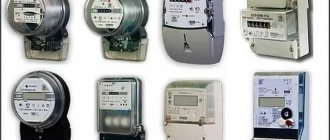
Types of testers
When operating electrical devices, digital megohmmeters of the model: F4101/4102 from 100.0 to 1000.0 V are widely used. Installers still work with tester brands M4100/1, 4100/5 and MS-05 m from 100.0 to 2500.0 V. The choice of megger size is based on rated resistance of the device under test: power cables and transformers, machines and insulators. To determine the state of insulation in electrical installations up to 1000.0 V, it is allowed to use megohmmeters from 100.0-1000.0 V, and in installations over 1000.0 V - 1000.0-2500.0 V.
Devices are also classified by the voltage generated and resistance limits in megohms:
- 500.0 V - 500.0;
- 1000.0 V - 1000.0;
- 2500.0 V - 2500.0.
Additional Information. The devices also differ in accuracy classes. The popular M4100 model has an error of no more than 1%, and the F4101 brand has an error of up to 2.5%. The selection of electrical installation testing devices is carried out taking into account acceptable performance indicators.
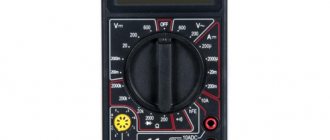
Electronic meter
Electronic meter
A digital or electronic tester is a modern type of equipment, equipped with a powerful generator with field-effect transistors. Measurements are made by comparing the voltage drop in a reference circuit with a fixed resistance. The results are shown on the panel. The test results saving function accumulates data for subsequent analysis. This model differs from analog devices in its compact size and light weight. Advantages of a digital tester:
- High level of accuracy, allows you to determine resistance over large sections of the circuit;
- convenient, easy-to-read digital panel;
- technological accessibility for measurement by one user;
- works great even in very busy spaces;
- convenient and safe to use.
Disadvantages of the electronic type megger:
- Requires external power source;
- high prices for products.
Electromechanical meter
Electromechanical device
These models have an analog display on the front panel of the tester and a hand crank used to rotate and generate voltage that passes through the electrical system.
Advantages of a manual megger:
- Remains important in today's high-tech world, remaining the oldest method for determining resistance values.
- No external source is required for operation.
- Low prices on the market.
Disadvantages of a manual megger:
- At least 2 people are required for operation, one to rotate the handle, the other to connect the megger to the electrical system being tested.
- Low measurement accuracy.
- Requires a large free space for placement.
- Provides an analog measurement result.
- High requirements for safety during use.
Circuit design features:
- Deflector and Control Coil - Connected in parallel with the generator, mounted at right angles to each other and maintained in polarity so as to produce torque in the opposite direction.
- Permanent magnets create a magnetic field to deflect the pointer using a North-South magnetic pole.
- Pointer - one end connected to the coil, the other deviates on a scale from infinity to “0”.
- A scale is provided at the top of the megger from the zero to infinity range and allows the user to read the value.
- Connecting a direct current (DC) source or battery.
- The test mode is generated by a generator for a manually controlled megger. A battery or electronic charger is provided for the digital megger for the same purpose.
Note! Current coil resistance helps protect the tester from any damage during testing due to low external electrical resistance