If your household fan is broken, do not rush to take it for repairs, much less throw it away. In some cases, malfunctions are so simple that eliminating them does not require special professional skills. In such circumstances, repairing a room fan with your own hands does not take much time, and the money savings are significant. Calling a technician to your home now costs at least 300 rubles in some service departments, not to mention the work, replacement of parts and the cost of the parts themselves in the services...
The fan does not rotate
. Check the presence of voltage in the outlet with a tester or multimeter. Or you can turn on any working household electrical appliance (iron, mobile phone charger, etc.) to diagnose the functionality of the outlet.
After making sure there is power in the outlet, unscrew the cover of the box with switching buttons on the fan stand.
Since the fan does not spin when the timer is turned on, and any of the speed buttons (0;1;2;3), it is logical to assume that there is no voltage supplied to the switch or the electric motor is faulty.
In the box you will see a motor rotation speed switch and a mechanical timer (time relay). One power wire goes directly to the motor contact, the second through the timer and 4 switch buttons to the various motor windings. First of all, you need to check the reliability of the switch contacts and the integrity of the wires.
This can be done with a multimeter by checking the presence of voltage at the output of the timer. To do this, its switch must be in the “ON” position. Then we turn on the speed buttons sequentially, checking the voltage at the output of each button.
In our case, testing shows that there is no circuit through the timer, which means the room fan does not work due to a malfunction in the contact group of the timer.
The contacts are two copper plates that are closed by an actuator under pressure from the rotating disc of the timer switch. When the set time is counted, the drive enters the slot on the disk, opening the contacts. The absence of an electrical circuit may be caused by wear of the drive mechanism, which does not press the plates sufficiently or oxidized contacts.
Troubleshooting Methods
The timer body is transparent, all mechanical gears, drive and contact positions are visible. The difficulty of repairing the timer yourself is that it is not recommended to unscrew and open the cover.
The gear transmission mechanism of the timer has a charged spring, the axes of the gears are pressed into the sockets of the top cover, which has locking elements. When you open the lid, you will release the spring, the gears will unwind and fly apart in different directions. Such repairs to a room fan should be carried out with the skills of a watchmaker.
At home, it is easier to carefully drill a hole Ø 5-8 mm above the contacts, through which you can use tweezers to bend the plates or clean the contacts. The hole will not affect the operation of the timer, then it can be sealed with transparent tape. After contact is restored, turn on the fan and check operation in all modes; if the result is positive, we assemble the structure to its original state.
If the drive mechanisms and contacts of the timer cannot be repaired, you can exclude it from the circuit by connecting the wire directly to the input terminal on the “0” button of the speed switch. This completes the fan repair.
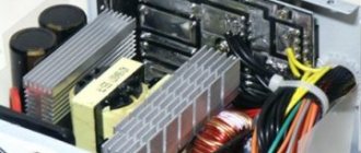
I got a substandard West SF-1602T fan (with a mechanical timer) made in China, sold by our company Ost-West, almost for free. The approximate cost of a similar one is about $20. The motor windings did not ring. For external wires only gray-blue 0.1k. The external capacitor has one end to the black common and the other to just one terminal from the windings (after opening, see below). Nothing more useful. I removed the rear engine casing (the rotating mechanism and external capacitor are still screwed onto it) and the middle part (plates with coils). The front casing with the rotor remained on the front panel of the fan as there was no need for manipulation. A detailed inspection of the conductor contacts revealed several breaks (as if rotted) of the coil leads under the cambrics. Restored contacts. Added definition: black (general)-red 1.0k. Naturally nothing works. As a result, an almost vandal attempt was made, but the only one, therefore the correct option (already doubtful) was to unsolder all the terminals of the coils. I didn’t think about resoldering the remaining contacts just in case, because it was already too late. I drew the conclusions with an accuracy of 99%. Three conductors came out from almost the same point - I didn’t sign them (well, it was inconvenient), I just sketched the location. After releasing the winding terminals from captivity, everything began to ring. Four windings - 1.0k, 0.2k, 0.1k and 0.7k. Using my sketches and logical calculations (about three conductors from one point), I reconstructed the connection diagram for the windings and capacitor (see figure)
Sketch of winding terminals:
Just in case, for possible connection experiments, all eight terminals of the windings using twisted pair cables (conveniently by color) were brought out of the motor casing. On the windings, I insulated all the wires with heat shrink and secured them around the circumference with a thick thread (as it was). Reassembled in reverse order). Everything worked. But the engine gets very hot!!! After five to ten minutes it’s already hot. It’s bearable to wrap your hand around, but the iron plates are hotter, and you can’t hold your finger on them for long. Where's the joint? I checked the rotor grout. I pulled the iron together normally. It couldn't have worked out better. The free movement seems to be good. This takes into account the fact that the design is without bearings, on ordinary bushings. I repeat, the circuit was almost certainly restored to the original one. If necessary, I will give my sketch of the winding terminals (for electricians who have been smoking the topic)). The photo will not be available due to the lack of the necessary device. Maybe the Chinese robot got it wrong? Maybe I need to connect it differently? Extending the ends of the windings 20 cm beyond the motor should not seem to affect heating. I checked the resistance on the fork of a similar but working fan (with a timer) - approximately the same (1.3k-1speed, 1.2k-2speed and 1k-3speed). On simple fans, the resistance is two times less. It seems that the starting winding with a capacitor can be used as a working winding if the device power is no more than 1.5 kW. If the windings are connected to each other in some other way, then this will no longer be an original circuit. But maybe it will be better? Or maybe this is how it should be heated (not sure)? I ask the guru for help! Thread with identical engine here
Most fans consist of switching circuits, starting circuits, and electric motor windings. The items on the list concern repairs. Often in household models, a trivial coil is used, wound with a copper core with varnish insulation. Today we will consider how to repair fans with your own hands, the inductance burned out, the wire broke due to the carelessness of the operator. To restore the coil, a good old device is used, despite its simplicity, you cannot get it in the store. With the help of a mechanism, inductors are wound using an electric drive, working with handles.
Industrial fans are different; unlike household fans, they are often centrifugal. The winding of a commutator asynchronous motor cannot be restored at home; it will be difficult to do. Craftsmen repeat the factory production cycle in their native lands.
Design of a typical floor fan
Do-it-yourself floor fan repair is on the agenda! You should start small: the simplest fans do not have a ground terminal. The device does not have a degree of electrical safety. The floor fan device includes a housing made of plastic. Water will get inside - expect a good shake. This type of floor fan should not be used near water. Starting with an aquarium with fish, ending with a flower vase. Particularly dangerous where small children live. If the thing falls, the child will guess to pour milk inside... Draw your own conclusions:
- the structure is unstable;
- the base breaks easily and bends;
- There is no protection against electric shock.
If a floor fan falls, there is a high probability that nothing will happen. Let's dive inside the structure. Let's leave aside for now the features of regulating the engine speed and buttons. Let's talk about the gearbox. The Krasnodar floor fan carries one asynchronous capacitor motor. The front side of the shaft is connected to the blades through a pin and a nut with a left-hand thread, the rear side goes to a gearbox formed by two gears, one double.
The shaft is equipped with a thread that engages the teeth of a large wheel as it rotates. The moment is transmitted to the small wheel, which drives the flywheel. The gear of the crank mechanism is the diameter of a hand, so the rotation is inferior to the speed of the original shaft of the asynchronous motor.
- The blades spin at full motor speed.
- The crank mechanism, thanks to the gearbox, moves more slowly.
Through the cardan transmission, the crank is hooked onto the leg, and the engine housing is mounted on the axle. When the shaft of an asynchronous motor rotates, the blades move smoothly in one direction or the other. However, you can stop the process. For a double gear, the roller is attached to the larger gear by two balls with a spring inserted into a through hole. If you pull the adjuster knob directly connected to the axle, the latch slides up. The connection between the gear and shaft is lost, and rotation stops. The mechanism provides fall protection: six grooves are cut into the inner mounting hole of the drive gear. Balls fit. There are six positions, the mutual transition is accompanied by a click, the axis rotates relative to the gear, the balls hit the walls, sliding into the grooves.
Clicking sounds are heard, there is a high probability that the floor fan has fallen. The drive is jammed, it works, clicking, a protective mechanism, protecting the motor from combustion.
We believe that the mode is unfavorable for a floor fan; if you do not turn off the device, the thermal fuse of the motor will certainly break. The gearbox is attached to the engine with three bolts and has a pair of lubrication holes through which the plastic gears can be lubricated. Refers to a drive rotating at the speed of an asynchronous motor.
Headache, how to fix a floor fan and assemble it. We see the situation: the relative position of the gearbox is incorrectly set, the legs through the gear, the head of the floor fan will move asymmetrically relative to the frontal plane. Can be annoying. Attach the gearbox, check the product by connecting power. Be careful not to get an electric shock, try to visually determine the correctness of the assembly.
Hood duct and grille with non-return valve
The first is that instead of corrugation, a plastic pipe is taken (for example, d-125mm), and through one or several bends it is led into the hole in the ventilation duct. In this case, a certain division is made in the hole itself under the ceiling.
An entrance to the pipe is mounted on top, and a small rectangle is left below through a grate with a valve for natural inflow.
Moreover, the grille should be at the bottom, and not at the top. Otherwise, the air flow from the hood will blow upward and lift the so-called non-return valve.
Although, of course, if you have a more advanced valve design - a circle or rectangle with an offset axis, and not simple strips of polyethylene, or there is a solid partition, then you can safely install it as you want - on top, side, bottom.
However, in fact, this whole structure often does not work as intended. When you turn on the exhaust unit and create pressure, a small part of the dust still seeps through the cracks and micro-holes, after which it safely ends up in your kitchen on the dining table.
No check valves are 100% effective. The bulk of the air, of course, goes outside, but the gradual formation of dust inside the apartment is a fact.
And even when the hood is turned off due to the reduction in the diameter of the original hole, natural ventilation through narrow grilles will be much worse.
Everything can be done much better.
Floor fan motor
Inside the fan there is an asynchronous motor with regulation of the shaft rotation speed by switching the windings. A capacitor is attached to the gearbox. The radio element is not a trigger element. We believe that it is not for nothing that the windings are fastened four in two rows, shifted relative to each other by an eighth of a turn. Field rotation uses voltage phase and 90 degree shift. The equipment is useless at this point, one winding of the asynchronous motor of the floor fan will burn out, and the motor will have to be replaced. It is not possible for a beginner to wind a complex product on his own.
Speed control is performed by switching the supply voltage to the appropriate wires by switching the buttons on the stand. One core goes from the cord from the outlet to the engine, and the position of the second is selected by the operator. Only one of the speeds is pressed at a time, which is ensured by mechanical methods of blocking parallel switching. Krasnodar products are pleased with the presence of backlighting: the top button ensures that the diode lights up. Allows you to avoid collisions with a floor fan in the dark. Indirectly indicates: the manufacturer is aware of the instability of the product.
The engine is made up of an insulated silumin rotor-drum, and the wiring of the coils is sealed. The structure remains unknown for obvious reasons; the question is meaningless. We believe that the probability of rotor failure is relatively small; the armature receives power from the stator. The structure is usually represented by a squirrel cage. A set of longitudinal conductors arranged in a circle, united by two rings at the ends. At both ends of the rotor there is an impeller that blows air over the stator coils. Allows the asynchronous motor to work harder. The Krasnodar floor fan has plastic impellers.
In case of uncertainty, test the wiring from the button (without disassembling the fan), examining the underlying fault. The resistance of the working winding is never zero, it is too high. The break is not difficult to guess. The starting winding rings from the contacts of the capacitor. The direction of rotation is determined by the relative position of the starting and main windings, therefore, if you mix them up, you will get the wrong result.
Of course, if at least one winding fails, the engine will not work. One phase is not enough to accelerate the rotor. Rotate the blades clockwise (with your hand withdrawn) to identify the presence of a characteristic malfunction. The floor fan will start working - one winding has burned out. It is incorrect to talk about starting and working coils; copper coils are identical. The motor is capacitor.
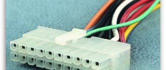
2 pin cooler wire pinout
The simplest cooler with two wires. The most common colors: black and red. Black - working negative of the board, red - 12 V power supply.
Here the coils create a magnetic field, which causes the rotor to spin within the magnetic field created by the magnet, and the Hall effect sensor evaluates the rotation (position) of the rotor.
How to disassemble a floor fan
From what has been said, it is clear: there is nothing to break inside the floor fan. This is a motor and a capacitor. The rest falls on the mechanical part, the gearbox. If there is whistling or noise, try lubricating the gears. How to do this is clear from what has been said. There are a couple of holes in the gearbox housing for these purposes. Solid oil is suitable for plastic parts.
Repairing a floor fan yourself shouldn't be too difficult. Replace the motor with one of suitable weight and size. The main types of breakdowns concern the mechanical part; restoration is carried out using conventional (welding plastic with polyethylene) methods with skilled hands.
3 pin cooler connector pinout
The most common type of fan is 3 pin. In addition to the negative and 12 volt wires, a third, “tacho” wire appears here. It sits directly on the sensor leg.
- Black wire – ground (Ground/-12V);
- Red wire – positive (+12V);
- Yellow wire – revolutions (RPM).
Subscribe to the newsletter
An exhaust fan is a device that can increasingly be seen in the homes of our fellow citizens. There are several reasons for this. Firstly, recently, thanks to a significant reduction in the cost of production of such devices, almost everyone can afford such a purchase. Secondly, this electrical appliance is certainly a very useful acquisition for an apartment or a private house.
Electrical circuit of a household fan and its features
The main task of an exhaust fan is to provide forced artificial air circulation in rooms where natural circulation is difficult or insufficient. A striking example of such a room is the bathroom. In apartment buildings, as a rule, this room is located far from the external load-bearing walls, and, therefore, air circulation in them is difficult. If we add to this increased humidity and the mold that arises from it, then it immediately becomes clear that an exhaust fan in the bathroom is not just a tribute to fashion, but a real necessity.
In order to connect the fan, you need to know a few small nuances. You need to understand that the electrical connection diagram of the fan is largely determined by the location of its installation and the presence of design features.
Basic connection diagrams:
1. Connection with built-in switch. The simplest scheme. The device is supplied with 220 V power. The fan is turned on and off using a switch built into the device.
2. Connection via a switch. Using this scheme, the fan is turned on and off using a special switch. As a rule, it is located in front of the entrance to the room. For such a connection, it is necessary to lay 2 cables - one from the junction box to the switch, the second to the device itself.
3. Connecting a fan with a timer. The peculiarity of these devices is that they do not turn off immediately, but after a certain time. This is done through a special time relay, which automatically turns off the device after a predetermined period of time (usually from one minute to half an hour). With this connection, one wire goes to the switch, and two to the device.
4. Connecting a fan with a humidity sensor. The electrical fan control circuit may include a humidity sensor that measures readings in real time and, in accordance with a given program, monitors the operation of the device - it turns it on when humidity rises and turns it off when it reaches optimal values. The device connection diagram is similar to that needed to connect a fan with a timer.
Most fans consist of switching circuits, starting circuits, and electric motor windings. The items on the list concern repairs. Often in household models, a trivial coil is used, wound with a copper core with varnish insulation. Today we will consider how to repair fans with your own hands, the inductance burned out, the wire broke due to the carelessness of the operator. To restore the coil, a good old device is used, despite its simplicity, you cannot get it in the store. With the help of a mechanism, inductors are wound using an electric drive, working with handles.
Industrial fans are different; unlike household fans, they are often centrifugal. The winding of a commutator asynchronous motor cannot be restored at home; it will be difficult to do. Craftsmen repeat the factory production cycle in their native lands.
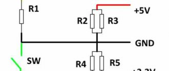
Assembly
In conclusion, I note that during installation and operation, one should remember that there is no galvanic isolation of the device (a disadvantage compared to a transformer circuit) from a 220 volt network. Author of the article: Nikolay5739 (Kondratiev Nikolay, Donetsk.)
Discuss the article CONNECTING A COMPUTER FAN TO A 220 V NETWORK
Fan composition
A typical fan includes:
- AC, DC motor;
- flywheel;
- buttons, relays, contactors;
- automatic regulation circuit.
Optionally there are no elements, the repair diagram looks like this:
- First of all, let's ring the motor windings. Regardless of the design, there are coils inside that give (on the tester screen) a resistance of a few to tens of ohms. Please note: the starting windings of asynchronous motors ring after the capacitor. The obvious point is that ignoring the rule leads to confusion. The capacitor rotates the voltage phase by 90 degrees, helping to create the correct field distribution inside the stator. If the motor is a commutator motor, the windings are connected in series (there is no capacitor). It is wise to ring the motor at the input, since the fault may be hidden in another place. Whether the break is detected or not, remove the brushes and take care of the commutator second. We call the sections one by one. If a malfunction is detected, the maintainability of the cooling fan is assessed by design. It's difficult to do, try to find a new manifold. Needless to say, the drum does not break in asynchronous motors with a squirrel-cage rotor. The current of the “squirrel cage” is relatively small; the copper rolled inside, on the contrary, is thick.
- Secondly, the serviceability of cores, relays, and buttons is assessed. The circuit rings, including the conditions for the thermostat to operate. The implementation method is determined by the design. Simulate heating by using a lighter to heat the sensor. The approach is reasonable in kitchen hoods and other appliances where the temperature is relatively high. The buttons are checked for the passage/interruption of electric current in their respective positions. Do-it-yourself repair of household fans often concerns switching. The buttons are pressed inaccurately and liquid spills. It is necessary to restore the correct functioning of the mechanical part and clean the contacts. Anyone who spilled jam on the TV remote control will understand the situation. The mechanism is disassembled, the contacts are cleaned. It would be useful to recall that the capacitor passes alternating current; in the best case, two operations are performed: they call the element to check for a short circuit (this is a breakdown), apply alternating current power and check the passage of the signal from the winding. We can say with complete confidence whether the capacitor is broken.
Scheme and principle of operation
To understand why this happens, you need to know the principle of operation of the kettle and its electrical circuit. The model range of these household appliances is very diverse, but the operating principle and assembly diagram are almost identical for all, with rare exceptions: for example, a built-in timer.
The electric kettle works quite simply: through a strong cord with a plug at the end, the voltage from the socket is transmitted to the XP1 contacts located in a massive stand - it is on it that the device is installed while boiling water. At the bottom of its body there is a special connector that interacts with the contacts of the stand.
The SA1 thermal switch provides manual switching on and automatic switching off of the device after the water begins to boil. The thermal protection switch is always active and does not take part in the daily operation of the product - it only works when the kettle is turned on without water. Then the current goes to the tubular heating element (TEN), and a glowing light on the indicator signals that the product is in operation.
When the water boils, steam collects in the free space between the water level and the lid of the product, then the water vapor flows through a special channel to a bimetallic plate made of two different metals, which bends when heated and opens the contacts - the thermal switch turns off.
How to wind a simple inductance for a fan
Those who have disassembled children's cars know that there is often an inductance inside, an ordinary wire coil. In household fans the picture is similar. Let's talk about ignition devices for electric stoves and other appliances. Inductors can be wound using a special device. You can repair fans yourself without resorting to the help of a specialist.
You will need a board. A half-meter piece of plywood supporting two pairs of posts. The wire will be wound from one, and a new inductor will be assembled on the other. The axis rotates freely between pairs of posts. To automate the process, provide devices for connecting a drive from a screwdriver, drill or other similar device. To manually rewind, use a handle, like the cameramen used in old films.
Before winding the inductor, unwind the old one. Ring the coil in advance so that the repair of duct fans and centrifugal fans does not involve unnecessary work. One end of the coil is the top. Which one is easy to understand by removing the electrical tape, another type of protective coating from the coils. The winding process begins. Clearly, you will need a frame. In the simplest case, you can get by with a wooden spool of sewing thread. When winding, excessive tension and loosening of the wire are unacceptable. Copper is pulled upward with a finger. The drive is turned on, and a second hand can optionally help. The break occurred at the beginning/end, use the wire to wind a new inductance. Otherwise, it is better to buy new components according to the measured length.
Regardless of the type of fan, winding is carried out in rows from the edge and according to the shuttle principle. The turns fit closer to each other, which is controlled by the finger of the hand holding the wire. The ends are brought out exactly as was done with the original coil; in order not to bother your head with details, it is recommended to take a photo with your mobile phone of what the household fan looked like before the repair. Applies to pads, terminals, buttons, relays and motor. Once the winding is finished, secure the ends. The coil is ringing. If the signal does not pass through, then the varnish insulation of the wire is to blame. Removable with an aspirin tablet and a soldering iron, repeat the combination before tinning. Take out the sting and wait for it to warm up.
At the same time, find a piece of electrical tape to wrap around the coil of a household fan. The wire stripped of insulation is ringed; if successful, tin it at both ends. The household fan is ready for use, assemble the electrical connections, put the coil in place, the repair is complete. Let's check whether the device works well from the network. If the engine makes an unpleasant sound, apply lubricant. Are the grinding and squeaking noises gone? The procedure was beneficial for the household fan. Noise is a significant factor when operating home appliances. Connect the fan control unit, the device is ready for operation.
Connect directly
If you initially abandoned junction boxes and use recessed socket boxes for switching, then the third connection diagram will be similar, and the differences here are practically not noticeable.
It’s just that all connections are made directly in the socket box. It can be done by crimping or using the same Vago clamps, if space allows.
There are also expensive, sophisticated models with remote controls.
They are connected in two ways:
directly from the distribution box - forced manual shutdown is performed by a button on the fan itself
via a separate light switch button
Household fans
Household fans vary in design and use similar technical solutions. Here is a short list of places where a rotating impeller is useful:
- Refrigerator compressors certainly have forced airflow;
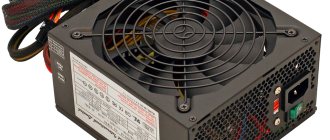
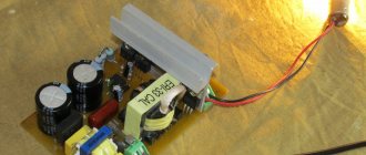
- Repairing the power supply fan is a common problem;
- each asynchronous motor contains a pair of impellers on the shaft for blowing the stator coils;
- no vacuum cleaner is complete without a motor with blades;
- The processor cooler is a smaller copy of a household fan;
- without a heater fan, not a single car interior will warm up properly, and repairing the fan fluid coupling has set some drivers on edge;
- kitchen, toilet and other hoods include a motor and an impeller.
An incomplete list of household appliances that use fans. The computer system unit is excessively noisy - the coolers will need to be lubricated. Carefully peel off the sticker on the fan housing with tweezers, the end of the axis comes out right here. Place a couple of drops on the sliding point and the noise should decrease. Where fans are found, the repair techniques listed above apply. Difference in size, purpose and other details.
Having studied the principles of inductance formation, begin replacing the motor stator coils. It’s a long, tedious process, it’s not recommended to do it, whoever decides to do it, take a photo of the part being repaired, bite out the wiring, wind the turns correctly, and make the reverse connection as needed. It sounds difficult, but it is more difficult to do. Often the coils have no casing. A coil of wires is inexplicably connected to neighboring coils. A household fan looks scary when disassembled. The stator has cuvettes under the wire, where it is difficult to place the turns. Nobody repairs household fan motors.
Ladies generally think that a disassembled fan is unusable, and they throw away the parts that were scattered here and there. Do not leave the opened device unattended.
I got a substandard West SF-1602T fan (with a mechanical timer) made in China, sold by our company Ost-West, almost for free. The approximate cost of a similar one is about $20. The motor windings did not ring. For external wires only gray-blue 0.1k. The external capacitor has one end to the black common and the other to just one terminal from the windings (after opening, see below). Nothing more useful. I removed the rear engine casing (the rotating mechanism and external capacitor are still screwed onto it) and the middle part (plates with coils). The front casing with the rotor remained on the front panel of the fan as there was no need for manipulation. A detailed inspection of the conductor contacts revealed several breaks (as if rotted) of the coil leads under the cambrics. Restored contacts. Added definition: black (general)-red 1.0k. Naturally nothing works. As a result, an almost vandal attempt was made, but the only one, therefore the correct option (already doubtful) was to unsolder all the terminals of the coils. I didn’t think about resoldering the remaining contacts just in case, because it was already too late. I drew the conclusions with an accuracy of 99%. Three conductors came out from almost the same point - I didn’t sign them (well, it was inconvenient), I just sketched the location. After releasing the winding terminals from captivity, everything began to ring. Four windings - 1.0k, 0.2k, 0.1k and 0.7k. Using my sketches and logical calculations (about three conductors from one point), I reconstructed the connection diagram for the windings and capacitor (see figure)
Breakdowns that you can fix yourself at home
Fan blade deformation
Happens quite often since the propeller itself is made of plastic. The blades may become deformed when exposed to high temperatures. As a result of deformation, the blades touch the protective mesh, and a characteristic unpleasant noise occurs. Usually the deformation is corrected manually, otherwise the blades and protection will very quickly become completely unusable.
Deformation of the protective fence
It usually appears as a result of a falling floor fan. The fence itself is made of relatively thin metal wire and includes two parts - front and back. The front part is very easy to remove, but the back part will require some fiddling. The propeller is removed from the electric motor shaft, after which the large plastic nut is unscrewed and then the guard itself is removed. After straightening, the protection is assembled in the reverse order.
Turns to the sides stop
The main reason for this could be a disconnected crank. It is necessary to disassemble the device body and tighten the fastening screws if they are loose or unscrewed. In addition, interruptions may occur in the turning mode. To determine the cause, the gear engagement of the gearbox is checked, as well as the operation of the switch. If necessary, the gearbox is lubricated with a special lubricant. In case of severe wear, it is recommended to replace the parts. If there are no replacement parts, the fan can be used in normal mode, without turning on the turns.
Switch fault
May cause interruptions in operation. To check its condition, you need to remove the switch and determine the condition of the contacts. If necessary, the contacts are cleaned with sandpaper.
The fan doesn't work at all
In this case, you should check the serviceability of the electric motor. If it turns out that the electric motor is faulty, then repairing floor fans, in this case, is not economically feasible.
Despite their simple design and the absence of any external negative factors, household fans break down. Even an exhaust fan can fail within a year. And this despite the fact that, in addition to the impeller with an electric motor, there is only one more switch. It would seem that there is nothing to break. But it all depends on the load on the exhaust fan.
Probably modern manufacturers of this electrical equipment, understanding its potential durability, decided to help themselves: by increasing the number of fans sold, purchased to replace broken ones. And in order for a breakdown to occur and occur in the future not so distant from the date of purchase, a small part is installed in the electric motor - a temperature fuse. And within about a year, with sufficiently long operation, this part burns out and the electric motor stops rotating.
After this, as planned by the manufacturer, the owner of the fan will go to the store to buy a new one. But instead, you can repair the electric motor yourself and save money. To do this, you will need to disassemble the case and remove the engine from it. Disassembly must be done carefully, taking into account the design features. And they are such that some parts can be glued. And in order not to break them, you will need to separate them along the glued seam with a knife blade.
The fuse is located in the engine. This is a very small part to which two wires are attached.
The purpose of the fuse is to break the circuit when the electric motor overheats and turn it off. But why “overheating” and breaking the electrical circuit occurs at temperatures that are not dangerous for the materials from which the engine is made is not clear. The body of the part indicates a temperature of 125 degrees Celsius. Fan engines from the times of the USSR did not contain such a part, and some of them still regularly spin the impellers. Therefore, it is possible to exclude this fuse from the electrical circuit, so to speak, “based on the experience of previous generations.”
Removing the faulty part:
To simplify repairs, we solder a jumper made of thin copper wire on the existing contacts. Then we insulate the resulting shunt with insulating tape.
We check the result of the work. Observing safety precautions, with the voltage turned off, connect the motor to the outlet. After this, we apply voltage and make sure that the shaft rotates. Lubricate the shaft bearings. We assemble the fan and continue to use it. Don’t forget to clean it from dust, dirt, and lubricate the bearings once a year.
Flange problems
Flanges, as a rule, are installed in fans made of plastic. If the device falls, they can easily break. In this case, repairing the fan will have to begin by unscrewing the back cover. If we consider simple models, their flanges are usually located near the electric motor. However, there are modifications where they are located near the shaft itself. In the first case, there is no need to remove the control unit. However, you will have to twist the crank first.
Next it is removed. After this you will need to disconnect the switch. The flange is primarily attached to the panel using screws. If it is severely deformed, then the easiest way to pry it off is with a screwdriver. However, if the damage is not serious, then it can be easily twisted. If we talk about models where the flange is installed near the control unit, then you should do it differently.
First of all, the fan is released. Then the control unit itself is twisted. The next step is to remove the gasket, which is located next to the rotor. In this case, the flange must be secured with two screws. To replace it, you will need to order a similar part from the service center.
Basic faults and repairs
The listed list of microwave oven malfunctions is not exhaustive; it only reflects the most common breakdowns. You can fix all of the listed faults yourself.
| Problem | Possible reasons | Solution |
| Microwave won't turn on | Power fuse blown, replace only | After replacing the fuse, check the serviceability of the transformer and the transformer safety diode |
| The clock is running | Miniature door switch does not operate | Repair or replacement |
| The microwave oven periodically turns off and on every few minutes | Cooling fan malfunction, fan switch relay, vents closed | Minor repair or replacement |
| During operation, sparks are visible and a burning smell is heard. | Breakdown of the mica gasket due to contamination | Replacement |
| Microwave doesn't heat well | low voltage in the network or loss of magnetron emission. Application of a voltage stabilizer | DIY repair by increasing the number of turns or replacing the magnetron |
| The LCD display does not display all segments, highlights and spots | The screen or processor is damaged. If the microwave also doesn’t work, then it’s definitely the processor. | Replacement |
| Touchpad stopped working | Damaged conductive paths | DIY repair by laying wires or replacement |
| The tray rotates jerkily | Roller grooves dirty, motor malfunction | Do-it-yourself repair by cleaning the roller grooves, replacing the engine |
| The light is on, the tray is spinning, the microwave is not heating | Severe voltage drop in the network, a breakdown in the transformer power circuit, a broken magnetron | Installation of a voltage stabilizer, repair by ringing the transformer power circuit with a tester, troubleshooting, replacement of the microwave generator |
| Buttons on the control panel do not turn on | Do-it-yourself repair by checking with a tester, soldering contacts or replacing buttons | |
| There is a humming sound when the microwave oven is operating | The fan, doubler diode or transformer has failed | Replacement |
| Microwave works without turning off | The voltage supply relay is faulty (contacts sticking) | Power off, replace. There may also be a problem with the processor or relay control circuit. Self-repair by checking with an ohmmeter, if the circuits are ok, replace the processor module |
You can repair a microwave oven with your own hands, but you can operate it correctly and thereby significantly increase its impeccable service life.
Every second kitchen uses a microwave to quickly heat up food; it is easy to use and saves quite a lot of time. Repairing microwave ovens Samsung, Panasonic, LG and others can easily be done with your own hands at home, without contacting service centers.
Despite the apparent complexity of the operation, any microwave consists of fairly simple parts: a food heating chamber, a magnetron, a waveguide and a winding, which is necessary to power the device. The camera and magnetron are connected to each other using a waveguide. In addition, a transformer and its winding are also installed in the furnace. The operating principle is as follows: when the microwave oven is turned on, voltage is supplied to the primary winding of the transformer. At the same time, energy is also supplied to the secondary winding, which is responsible for heating the cathode. Both windings are very well insulated.
Photo - microwave oven design
It should be noted that this device uses doubling the voltage, which is why the food heats up at such a speed. For this function, a capacitor is used, to which a rectifying diode is connected in parallel. To control the time, a timer is used on the gears, which helps control the duration of heating. A special temperature sensor also has a similar function.
Photo - diagram
Considering that this device is an increased source of danger, it has a built-in system that is responsible for the safety of use. These include phase and power protection relays that stop the microwave oven when there is a power surge or the door is open.
Photo is a simple device
The most common problems faced by microwave oven owners are:
Video: repair and diagnostics of microwave ovens