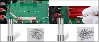
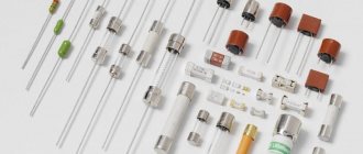
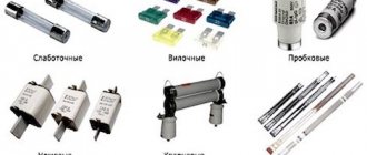
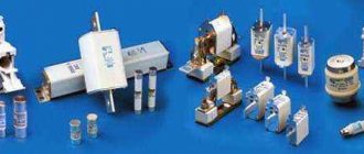
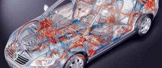
Fuses are of great importance in the operation of any modern car. They protect the machine’s electrical circuit from breakdowns, failure of electrically dependent equipment and expensive repairs that can result from a short circuit. Almost every driver has encountered a safety block; many have had to replace burnt-out elements. There is nothing complicated about this, and everyone can cope with the task on their own.
But the very fact of blown fuses is an unpleasant sign. It means that there are some problems in the car. When fuses fail literally immediately after replacement, or after a few days or weeks, and this happens regularly, you need to look for the cause. A simple permanent replacement will not solve the problem.
Before changing the fuse itself, the motorist must find out why it fails.
Main reasons
Each fuse is responsible for the stable operation of certain electrical circuits. If the low-melting element melts, then some kind of malfunction has occurred. Sometimes such situations are isolated, that is, after replacing the fuse, the problem does not recur. But often it turns into a trend.
Experts identify several main reasons why protective fuses burn in a car. If you understand the reason and find the source of the trouble, you will be able to return the machine to normal operation.
- bad connection. It is possible that during installation or during operation on uneven roads, the quality of contact between the fuse and the block was impaired. Sometimes it’s all about the quality of the products themselves, which are not able to guarantee a tight connection. In this situation, the best solution would be to purchase higher quality security elements,
- wear. There is a fairly widespread opinion that the first time the load on the fuse is exceeded, it immediately fails. This is not entirely true. When the situation is critical and the load is really huge, the fuse element is immediately destroyed to break the circuit. But when the load is only slightly higher than normal, the fusible component gradually fails. The cross section decreases, and as a result, after several load sessions it finally burns out. Since fuses are consumables, they tend to fail without causing serious problems in the car itself,
- wrong choice at face value. Each fuse has its own rating. This is the current strength that he is able to pass through himself. If an element with an incorrect value is installed, it cannot withstand the load acting on it and quickly fails,
- sudden surges in voltage. If a sharp surge occurs in the electrical circuit for which the fuse is responsible, the element melts and fails,
- disturbances in the current path. Each fuse is designed for a specific load and is installed on the electrical circuit corresponding to its rating. If you shorten the length of the circuit, the resistance will decrease, and the fuse will pass a higher current through itself. On modern cars, electronics are not designed to withstand overloads. Therefore, special sensitive protective elements are installed in their electrical circuits. Under critical loads, they melt and break the circuit, thereby protecting the equipment from breakdowns.
When devices and components that depend on electricity fail in a car, it is recommended to first check the condition of the fuses before repairing or replacing them. They could simply burn out, causing the systems to stop working. A simple replacement of the element will restore functionality.
Let's go on reconnaissance
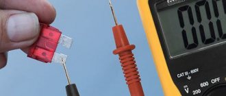
Not sure which fuse is blown because you don't have a diagram? You can always take them all out one by one and inspect them. It is faster to do this with a voltmeter or diagnostic lamp. The conductors inside the blade fuses are exposed on the top surface. Turn on the ignition and the electrical circuit that needs to be checked. Connect the ground wire of your voltmeter or test lamp to a reliable chassis ground point - bare metal. Touch the fuse wire with the probe. A good fuse should show voltage on both sides. A burnt out one will not show any voltage on one side.
What to do when a fuse blows
Novice motorists are naturally interested in what they need to do in situations when a car fuse blows.
Remember that the cost of these elements is significantly lower than the price of the equipment they protect. These are actually cheap consumables. You can purchase them as a whole set and always keep them on hand in case problems arise, the old device burns out and requires replacement.
Don't worry if the fuses blow. This is an absolutely normal situation for any car, regardless of the make, model, year of manufacture, etc. That is, this happens both on old cars and on brand new expensive foreign cars. No electrical circuit has 100% protection against current and voltage surges.
But you need to react completely differently when burnout becomes regular and constantly repeats even after replacing components. In such a situation, you should diagnose the car and check what is wrong in the electrical system. Moreover, it is strongly recommended to begin diagnosis as soon as possible after the first symptoms are detected.
If you installed a new fuse and it burned out almost immediately, then the car owner's task is to identify the source of the problem. To achieve the desired result, a number of activities should be carried out:
- Using the technical documentation for your vehicle, check which devices and equipment are connected to the problematic fuse. These instructions must indicate which fuse is responsible for what,
- now you need to turn on all systems and equipment for which the constantly burning protective element is responsible,
- take a screwdriver, the handle of which must be insulated. Use a metal part to touch the terminals on which the fuse is attached, either inside or outside the block,
- if a spark occurs at the moment of contact, there is some kind of malfunction in the electrical circuit,
- disconnect one of the previously switched on consumers, then repeat the manipulations with the screwdriver,
- when, after turning off the next device, the spark disappears, this will allow you to determine the culprit. This is what causes your fuse to blow.
Since you have managed to identify the source of the trouble, the appropriate repair or replacement of the unit is carried out. Further work directly depends on what exactly is wrong. If possible, you can fix the problem yourself. In case of serious malfunctions, which you have years of experience in eliminating, it is better to contact specialists.
When the cause of blown fuses has been eliminated, you can finally install a new protective element and continue operating your vehicle.
Don't have a spare?
Some car manufacturers do not produce spare fuses or even leave space under the dashboard to store them. Even if you have spares in your fuse box, chances are there are only a couple of them and not of all sizes.
This holder collapsed after the clamp burned out.
Go to an auto parts store and buy a set of fuses. For less than 300 rubles you will purchase a box containing an assortment of fuses and pliers for them. Keep them dry and clean in your glove compartment.
Checking burnt elements
Motorists should understand how to check the fuses in their car. An overload in the electrical network does not always lead to failure of the fuses themselves. They are the easiest to check, so diagnostics usually start from here.
When an electrical appliance stops functioning, it is far from certain that the protective element is to blame. Here the most correct and rational solution would be to check the status of the device responsible for the faulty device in the car.
A fuse map will be a very useful tool in the diagnostic process. On all modern cars it is located directly on the cover of the safety block.
There are several main verification methods:
- visual,
- replacement method
- multimeter.
The simplest method is considered to be by replacement. You just need to install a new fuse in place of the potentially faulty device. But it is fair to consider this technique identical to visual inspection. After all, it is easier to determine by external aspects than to change each of the fuses located in the block in a row.
Visual inspection
Let's start with how to understand whether a fuse has blown in a car, based purely on the appearance of the element. This method is considered the most correct, since it is quite easy for many people to visually verify that a breakage of a low-melting component has occurred.
To check, you will need to remove the element, bring it to the light and look at it carefully. It will not be difficult for an experienced motorist to find out and understand whether the fuse in his car has blown or not. Beginners do not understand this right away, which raises several more questions regarding how to get an accurate answer.
A worn fuse is not difficult to identify. This manifests itself in the form of broken wire (low-melting alloy) or burnt marks. Symptoms such as these indicate that the electrical circuit has broken and the fuse needs to be replaced.
A similar testing method is relevant for those fuses that are made from glass or transparent plastic. Most of them are found in passenger cars.
But the method also has a significant drawback. The test is performed by a person, without the use of any instruments. In some cases, especially for beginners, a visual examination does not provide a 100% guarantee of a correct diagnosis. Therefore, it is much more correct and efficient to check fuses using multimeters.
Checking with a multimeter
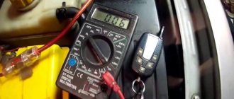
This is a great way to identify a blown fuse in your car. Anyone can calculate using this method, since there is nothing particularly complicated in the procedure. The only condition is to have a multimeter. You can also check with a regular tester, but a multimeter can later solve a number of other issues. This is a more versatile device. Having a car multimeter in your hands, you should understand in more detail how to independently check a potentially blown fuse.
Using such a device, verification is performed using 2 methods:
- by voltage,
- by resistance.
Let's start with a technique that involves checking the condition by voltage. Here you need to perform the following procedures:
- turn on the measuring device in voltage test mode,
- turn on the electrical circuit of the machine where there are problems,
- check the voltage parameters on one terminal of the protective element, and then on the second,
- if there is no voltage at one of the terminals, the device has burned out and needs to be replaced.
The method is extremely simple, for which it is appreciated by motorists. Just a couple of minutes is enough to verify that the fuse is working or confirm that it has failed.
But in certain situations, checking by voltage is not very easy. This mainly concerns the fuses responsible for the operation of the horn and door lock. This is where an alternative method comes to the rescue.
If for some reason the voltage test is not suitable for you, use the resistance diagnostic method.
- The multimeter switches to Ohm measurement mode. These are units of resistance
- the terminals of the measuring device are connected to the terminals of the fuse,
- if the screen is zero, the element has failed and needs to be replaced.
And there is nothing complicated here, because even a novice motorist who has only recently started operating a vehicle independently can easily cope with the task.
In fact, to check you only need a little free time and a good multimeter with the appropriate measurement modes. It’s not difficult to buy a device, but its capabilities are enormous in terms of self-diagnosis of a car.
It's better to light one candle
Modern cars and trucks are very dependent on their electrical systems. Such a system in your car may produce more energy than was once available in your great-great-grandfather's house. You may find three different fuse boxes on your vehicle and several dozen fuses. Unlike home electrical panels, which rely on resettable, reusable circuit breakers, most automotive electrical circuits use resettable fuses that can only be used once.
Description for pre-restyling
Block under the hood
General photo - diagram
Description of fuses
| F1 | Not used |
| F2 | Not used |
| F3 (25) | Chains: fuel pump and ignition coils; main relay K5 of the engine management system |
| F4 (15) | Air conditioning compressor electromagnetic clutch circuit |
| F5 (40) | Power circuits: low speed cooling fan short circuit relay |
| F6 (60) | Circuits protected by fuses F9, F10, F28, F29, F30, F31, F32, F36 of mounting block 1 in the passenger compartment |
| F7 (60) | Circuits protected by fuses F13, F14, F15, F16, F17, F18, F19, F20, F24, F26, F27, F37, F38, F39 of the mounting block in the passenger compartment |
| F8 (60) | Circuits protected by fuses F1, F2, F3, F4, F5, F11, F12 of the mounting block in the passenger compartment |
| F9 (25) | Circuits under voltage in position S and A of the ignition key |
| F10 (80) | Power circuits of the interior electric heater relay |
| F11 (50) and F12 (25) | ABS control unit circuits |
Relay designation
- K1 - High speed cooling fan relay
- K2 - Air conditioner relay
- Short circuit - Low speed cooling fan relay
- K4 - Fuel pump and ignition coil relay
- K5 - Main relay of the engine control system
- K6 - Not used
- K7 - Fog lamp relay. If it is not there, then the PTFs are not installed.
- K8 - Heater fan relay
Other versions of this block.
In this case, you can download the full description here.
Block in the cabin
Located at the end of the dashboard on the driver's side behind the cover.
Scheme
Decoding
| F1 (20) | Chains: windshield wiper; tailgate glass heating relay coils |
| F2 (5) | Circuits: instrument cluster power supply; relay windings K4 of the fuel pump and ignition coils; the power supply to the engine control system ECU is from the ignition switch; |
| F3 (10) | Brake light circuits |
| F4 (10) | Chains: turn signal lamps; engine management system diagnostic connector (pin 1); immobilizer coils; switching block |
| F5 (5) | Rear gearbox electromagnetic clutch control circuit |
| F6 | Reserve |
| F7 | Reserve |
| F8 | Reserve |
| F9 (10) | Left headlight low beam circuit |
| F10 (10) | Right headlight low beam circuit |
| F11 (10) | Circuits: high beam lamps of the left headlight; high beam headlight indicator in the instrument cluster |
| F12 (10) | Right headlight high beam lamp circuit |
| F13 (30) | Rear door power window circuits |
| F14 (30) | Front door power window circuits |
| F15 (10) | ABS control unit circuit |
| F16 (15) | Driver and front passenger seat heating circuits |
| F17 (15) | Audio circuits |
| F18 (10) | Circuits: left side headlight lamps; left rear side light bulbs |
| F19 (10) | Circuits: side light bulbs of the right headlight; side light bulbs for the right rear light; license plate lamps; glove compartment lamps; Illumination of the instrument cluster and controls on the instrument panel, console and floor tunnel lining |
| F20 (7.5) | Rear fog lamp circuit |
| F21 (5) | Exterior mirror heating element circuits |
| F22 | Reserve |
| F23 | Reserve |
| F24 (5) | Power steering control circuit |
| F26 (5) | Airbag control unit circuit |
| F27 (20) | Chains: parking sensors; reversing lamps; windshield and tailgate glass washer |
| F28 (15) | Circuits: interior lamps; trunk lamps; backlight lamps for the head unit of sound reproduction |
| F29 (15) | Circuits: intermittent windshield wiper; turn signal switch; hazard switch; central locking control; buzzer; engine management system diagnostic connector |
| F30 (20) | Central lock chains |
| F31 (15) | Fog light circuit |
| F32 (30) | Heated tailgate glass relay power circuit |
| F33 | Reserve |
| F34 (15) | Rear gearbox electromagnetic clutch circuit |
| F35 | Reserve |
| F36 (30) | Heater fan relay K8 power circuit |
| F37 (5) | Electric drive circuits for exterior rear view mirrors |
| F38 (15) | Cigarette lighter renault duster; power supply to the head unit for sound reproduction from the ignition switch |
| F39 (10) | HVAC Motor Relay |
Separately, under the anti-theft device, along the dashboard beam, there can be a relay for an additional interior heater (1067 - 1068), and under the instrument panel a rear window heating relay (235).
Block in the cabin
It is located under the instrument panel, behind the protective door.
Option 1
Photo
cigarette lighter fuse
Scheme
Description
- Rear window wiper
- Mirror/outside mirror
- headlight
- Electrically adjustable outside rear view mirror
- Door lock
- Front wiper
- —
- Reversing lights
- Direction indicators
- Rear defogger (heating)
- Rear fog lights
- Instrument cluster
- Fan Motor Control Module
- Airbag
- Anti-theft/data link connector
- Transmission control unit
- Rear power windows
- Radio receiver, remote keyless entry, remote access
- Engine Control Module (ECM) / Anti-Theft
- Heated mat
- Cigarette lighter
- Stop signal
- Starter
- Radio/Clock/Remote Keyless Entry
- Airbag
- Interior lamps
Option 2
Photo example of a block part
Full scheme
Designation
- —
- —
- Heater, ventilation and air conditioning switch
- Seat heating
- —
- Fan
- Body control unit 4
- Body control unit 5
- Body control unit 7
- Dashboard
- —
- Airbag
- Radio
- —
- Reversing lights
- Body control unit 1
- Body control unit 2
- Body control unit 3
- Body control unit 6
- Body control unit 8
- Heater, ventilation and air conditioning
- Data link connector
- Logical ignition sensor
- Outside rearview mirror
- Spare fuse
- —
- —
- Dashboard
- Airbag
- Rear power windows
- Front electric windows
- Cigarette lighter
- —
- Ignition relay
- Logic mode relay
- Auxiliary power relay
- —
- Radio
- Heater, ventilation and air conditioning
- —
- Spare fuse
- Spare fuse
- Spare fuse
- Spare fuse
- Spare fuse
- Spare fuse
Block under the hood
It is located next to the washer fluid reservoir, under the protective cover.
Description
Option 1
| F1 | 10A Emission control system |
| F2 | 15A Emission control system |
| F3 | 15A Emission control system |
| F4 | 10A Emission control system |
| F5 | 30A Diesel combustion products filter evaporator, Glow plug control system |
| F6 | 3A Anti-lock braking system. Maintaining sustainability. Ignition |
| F7 | 7.5A Powertrain control module |
| F8 | 20A Cooling Fan |
| F9 | 30A Left windshield wiper |
| F10 | 30A Right windshield wiper |
| F11 | 10A Air conditioning compressor clutch |
| F12 | 20A Glow plug for the evaporator of the diesel combustion product filter |
| F13 | Reserve |
| F14 | 30A Emission control system - ignition |
| F15 | Not used |
| F16 | Not used |
| F17 | Not used |
| F18 | 40A Anti-lock brakes, stability control pump |
| F19 | 30A Starter Solenoid |
| F20 | 60A Glow plugs |
| F21 | 60A Ignition relay 3 |
| F22 | Reserve |
| F22 | Reserve |
| F23 | Reserve |
| F24 | 7.5A High Pressure Fuel Pump |
| F25 | Reserve |
| F26 | Reserve |
| F27 | Reserve |
| F28 | Reserve |
| F29 | Reserve |
| F30 | 40A Cooling fan 1 |
| F31 | 40A Fan 2 cooling systems |
| F32 | 60A Electric motors (two) windshield wipers |
| F33 | 20A Start-stop auxiliary water pump |
| F34 | Reserve |
| F35 | 15A Power supply for powertrain control system |
| F36 | 15A NOXI 2 sensor |
| F37 | 7.5A Volume control valve |
| F38 | 7.5A Mass air flow sensor |
| F39 | 15A Diesel Pump Fuel Evaporator |
| Relay | |
| R1 | Ignition |
| R2 | Starter |
| R3 | Rear window wiper |
| R4 | Not used |
| R5 | cooling Fan |
| R6 | Windshield wiper - on and off |
| R7 | Windshield wiper - low and high speed |
| R8 | Not used |
| R9 | Not used |
| R10 | Air conditioning compressor clutch |
| R11 | Evaporator system fuel glow plug |
| R12 | High pressure fuel pump |
| R13 | All Wheel Drive Pump |
| R14 | Econetic system |
| R15 | Cooling fans: high speed and low speed |
| R16 | Emission control system |
| R17 | Powertrain Control Module |
| R18 | Cooling fan - high speed |
Option 2
| F1 | 5A Switching off the radio sound |
| F2 | Reserve |
| F3 | Reserve |
| F4 | Reserve |
| F5 | Reserve |
| F6 | 15A Nitrogen oxide sensor |
| F7 | 15A Particulate Sensor |
| F8 | 20A High Speed Cooling Fan |
| F9 | Reserve |
| F10 | Reserve |
| F11 | Reserve |
| F12 | Reserve |
| F13 | Reserve |
| F14 | Reserve |
| F15 | Reserve |
| F16 | Reserve |
| F17 | Reserve |
| F18 | 40A Cooling Fan 2 |
| F19 | 40/60A cooling fan |
| F20 | 40A Emission control system |
| F21 | 40A Glow plug 2 |
| F22 | 40A Glow plug 1 |
| F23 | 10A Air conditioning compressor clutch |
| F24 | Reserve |
| F25 | 15A Right headlights with high intensity discharge lamps |
| F26 | 15A Left headlights with high intensity discharge lamps |
| F27 | Reserve |
| F28 | 5A Heating element for positive crankcase ventilation valve |
| F29 | 7.5/15A Coolant pump |
| F30 | 40/60A Powertrain Control Module Relay |
| F31 | 20A Run-start relay 2 |
| F32 | 20A Fuel fired auxiliary heater |
| F33 | Reserve |
| F34 | Reserve |
| F35 | 20A Powertrain Control Module |
| F36 | 20A Power wire 5 car |
| F37 | 15A Tank with reagent. Exhaust gas recirculation valve |
| F38 | 10A High speed cooling fan. Air conditioning compressor clutch. Low speed cooling fan. High and low speed cooling fan relay. Relay coils R1, R5, R10, and R15 of the engine electrical junction box |
| F39 | Glow plug control system |
| Relay | |
| R1 | High speed cooling fan |
| R2 | Not used |
| R3 | Rear window wiper |
| R4 | Air suspension module |
| R5 | Cooling Fan |
| R6 | Not used |
| R7 | Left headlights with high intensity discharge lamps |
| R8 | Right headlights with high intensity discharge lamps |
| R9 | Starter |
| R10 | Air conditioning compressor clutch |
| R11 | Not used |
| R12 | Not used |
| R13 | Emission control system catalyst |
| R14 | Not used |
| R15 | Low speed cooling fan |
| R16 | Not used |
| R17 | Not used |
| R18 | Powertrain Control Module |
Read with this
- Device, circuit and connection of the intermediate relay
- What is a solid state relay, purpose, operating principle
- Two time relay circuits with turn-off delay for 220V
- Conventional graphic and letter symbols of relays on electrical diagrams
- Marking of railway automation and telemechanics relays
- Electromagnetic relay 12v 4-pin soate
- Fuses
- Operating principle and connection diagram of a time relay
- What is a relay: types, scope of use, main characteristics
- Purpose of the thermal relay
Algorithm for working with a microwave oven
Most modern microwaves do not have high-voltage fuses, so the mains protector takes over the responsibility. But it burns out only if the transformer receives double load. In the event of a breakdown, you must perform the following actions:
- Disconnect the product from the network.
- Open the top cover; expose the body of the high-voltage device and check that everything is intact.
- If the filament burns, remove the fuse from the housing, check the contacts for burning, clean them, insert a new element with the same parameters.
For those users who are new to the oven, additional recommendations are needed. To remove the top cover without any problems, you first need to find all the fasteners and carefully remove them from their sockets. During a visual inspection, you can use a magnifying glass to accurately determine the presence of a thread, and also clearly see the markings on all elements. A new fuse must be purchased with a blown one, so that they are identical, otherwise the thread may burn out immediately after switching on.
