To safely use your home electrical network, you need to ensure its reliable protection. The vast majority of users understand this, which is why automatic circuit breakers are installed in all power lines, and often RCDs are installed along with them. However, these devices are not enough to protect the network from all negative factors. The machine will save the line from overload and short circuit, the RCD will protect people and pets from injury from leakage current. But if a problem occurs in a three-phase network (this could be a break in one of the three phase cables, a neutral conductor, or a pulsed voltage surge caused by a thunderstorm), these devices are useless. You can prevent negative consequences by connecting a 3-phase voltage control relay.
Three-phase voltage relay: purpose and principle of operation
This device, as the name implies, is designed to control the potential difference in a three-phase network. Its indicator is 380V. Of course, there are small limits within which the voltage can fluctuate without harming the wiring and connected equipment. But if it becomes too high or, conversely, low, serious problems arise.
Too much voltage causes the cable insulation to overheat and melt. In addition, under its influence, household appliances connected to the circuit burn out. If the potential difference is too small, then due to a decrease in power, malfunctions begin in the operation of the equipment, and some devices turn off. For electric motors, the consequences of a voltage drop are even more serious - the units simply burn out. By installing relays to monitor the phases, these problems can be prevented.
Many owners of private houses are deterred from purchasing a phase control relay by the fairly high price of the product. But installing this device in a three-phase network is completely justified, because eliminating the consequences of a line failure along with the connected devices will cost tens or even hundreds of times more. Not to mention that a voltage failure in the 380V network can cause a fire.
Nowadays there are various types of ILVs on sale, differing from each other in design features and functionality. But they all work on the same principle.
The mains voltage monitoring relay (3-phase) has a microcontroller in its circuit, through which the device monitors the potential difference across the phases.
When the voltage on one conductor changes under the influence of the controller, an electromagnetic relay is switched on. This happens automatically. The contacts of the device open and the power supply to the line is stopped. After the voltage parameters return to normal, the current will be released into the circuit again. No outside intervention is required for this.
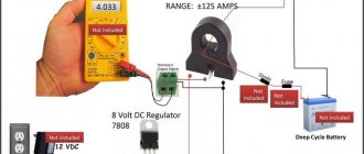
To check the RKN, you can use a tester. If the device is working properly, then when the multimeter probes touch contacts numbered 1 and 3, the number “1” should appear on the display of the measuring device. When the probes close contacts 2 and 3, the tester should show “0”.
Three-phase voltage monitoring relay: purpose and application
Prerequisites
Three-phase power supply is used not only to connect consumers that load three phases at the same time.
Residential buildings in all populated areas, holiday villages, the private sector, administrative buildings and more are also connected to a three-phase network. But at the same time they are consumers of a 220 Volt phase network.
And all three phases are distributed among consumers so that presumably the same load is obtained for each phase.
Schematically, a network with three voltage phases is depicted as an equilateral triangle. Its vertices are phases A, B and C. The length of each side corresponds to a value of 380 Volts in the absence of load or when its value is small.
The median segment from the vertex to the intersection point of the medians is the phase voltage. With a symmetrical load, the length of each side, that is, the linear value, decreases equally. The same applies to phase values.
But since real consumers can be anything, the load always turns out to be asymmetrical.
Advice
And therefore the triangle turns out to be scalene, illustrating voltage deviations from 380 and 220 Volts. It is clearly noticeable that with an asymmetric load, all phase quantities have changed. Therefore, consumers connected to a phase with minimal voltage and who are grinding coffee at this time will not be able to prepare it efficiently. Coffee grinders will operate at reduced speed.
Three-phase electric motors, especially loaded ones, will begin to work with rotor swings. And this can lead to destruction of conveyor belts and cables due to jerking.
It will be even worse for all consumers without exception if the neutral breaks. In this case, the change in phase voltages can significantly exceed 220 Volts. And this is dangerous for household electrical appliances.
Not to mention loaded three-phase motors.
Principle of operation
To avoid problems that arise in the load due to phase imbalance, zero breaks, or incorrect phase sequence, it is turned off with a special relay.
There are many models of such relays on the market, more or less complex in design. Some of them use semiconductor devices and even microprocessors.
For electrical networks in residential buildings, cottages and the private sector, three-phase voltage relays are installed at distribution substations.
Industrial enterprises use all three connection phases everywhere. Therefore, three-phase voltage relays are used more widely, mainly to protect electric motors. It has contacts designed to control magnetic starters and switches.
The voltage control relay coils in a three-phase network are triggered by a signal that is separated from the electrical network by special harmonic filters. When such a signal appears, the coil of the starter or similar switch is de-energized by the relay contacts and the load is turned off.
Most models of such relays are equipped with regulators for setting certain parameters to obtain the necessary controlled values of three-phase voltage and the time between disconnecting and reconnecting the load.
The operation of the relay to protect the load from mismatch of three-phase network parameters occurs most often in automatic mode.
note
Human intervention is usually only required for long-term accidents. In such cases, repeated trips occur, and then you have to manually turn off the input switch. But it is possible to automate this process. After several repeated turns on and off, a signal will be generated to automatically turn off the input switch.
Installation procedure
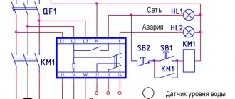
Control relays are usually installed on a DIN rail. Devices may differ from each other in connection diagram, but since it is printed on the body of the device, there are usually no problems with connecting the RKN. The connection of the input contacts to the line should be made through the starter.
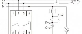
The relay connection diagram is shown in the figure below.
It is important to ensure good contact on all connections. Twisting, especially when connecting cables to the contactor, should not be done. It is best to purchase special tips for this purpose - they are quite inexpensive.
The RKN is connected to a three-phase electrical network via wires. Copper cables with a diameter of 1.5-2.5 square meters. mm are quite suitable for this purpose.
Video about the connection:
Connection diagram and installation of voltage relay
Most relays are mounted in the distribution panel on a DIN rail. They can be installed in any position while maintaining their functionality. However, the connection diagram will be different for different models, so it is applied to the body of each device.
This makes it easy to connect the three-phase voltage monitoring relay to an electrical circuit, following the same rules for all types of these devices.
The input contacts are connected to the network through a contactor or a special starter. The conductors of all three phases are connected to the corresponding terminals located on top of the device. The phases are marked with the letters A, B and C, and the terminal for the neutral wire is marked with the letter N.
The lower terminals are numbered 1, 2, 3 and are connected in the following sequence:
- From terminal No. 1, the conductor is connected to one of the outputs of the coil located in the contactor.
- Terminal No. 3 is connected to any phase that bypasses the voltage relay.
- The second output of the contactor coil is connected to the neutral conductor of the three-phase network.
The connection of power elements is carried out as follows. Each phase supplying voltage is connected to the corresponding input terminal of the contactor. The conductors leading to the load are connected to the output terminals of the contactor. To connect neutral conductors, a common neutral bus is installed in the distribution panel.
The contacts of all connections should be as tight as possible, so it is advisable not to use twists, especially when connecting conductors to the contactor terminals. There are special tips that provide reliable contact. All connections are made using copper wires with a cross-section from 1.5 to 2.5 mm2.
How to set up a voltage relay?
Let's look at the procedure for setting up the device using the VP-380V device as an example. When the device is already connected to the circuit, you need to apply power. Then look at the display readings:
- Until voltage is applied to the device, the numbers displayed on it blink.
- The appearance of dashes on the display may indicate a changed phase sequence, or the absence of one of them.
- If the connection is made correctly and the network parameters are normal, after 15 seconds the relay contact 1-3 closes and power begins to flow to the contactor coil, and then to the line.
- If the device screen flashes for a long time, the contactor will not turn on. Check the connection - most likely there was an error somewhere.
After making sure the connection is correct, you can proceed to the settings. Next to the relay screen there are 2 setting buttons with triangular symbols.
On one button the apex of the triangle points up, on the other - down. To set the maximum shutdown limit, press the top button. You need to hold it in this position for 2-3 seconds. A number corresponding to the factory level will be displayed in the central part of the monitor. After this, by pressing the buttons, you should set the desired upper limit for turning off the control device.
The lower limit is set in a similar way. The device will be programmed automatically 10 seconds after the setup is completed. In this case, all set parameters will be saved in the relay memory.
How to set the restart time?
On the body of the device, next to the display, there is a button for setting the restart time. It is located between the ▲ and ▼ buttons, indicated by a clock icon. After pressing and holding it, the setting number set at the factory will appear on the display. Most often it is 15 seconds.
What does this feature do? If, for example, a potential difference occurs on one phase that exceeds the limit values, the relay will turn off the power to the network.
After the voltage is normalized, the control device will turn on the electricity supply after the period set at the factory (15 seconds). To change the value, hold the setting button until this number appears on the screen. After this, set the desired number by manipulating the upper or lower button. The change step provided by the device is 5 seconds.
How to adjust phase imbalance?
To set the interval between voltage readings on different phase conductors, press the upper and lower buttons simultaneously. The factory setting value will appear on the screen; as a rule, it is 50V. This means that the relay will stop supplying power if the voltage difference between the phases is 50V.
You can change this value by pressing both buttons at the same time, and then setting the upper or lower number to the desired number.
More details about the settings using the example of one of the models in the video:
Input 2
Here I photographed the input machine:
2 – Input automatic switch (switch) to the meter
Three-phase input differs fundamentally from single-phase. More details in my article.
And the electrical panel looked like this:
2 – appearance of the electrical panel
The meter has a magnetic seal. Why it is needed - I refer you to the article about Ways to Steal Electricity. But I say again - you need to live honestly!
2 – Magnetic seal on a three-phase meter
Appearance of the place where there will be a gap for connecting our voltage control relays:
2 – counter outputs
Closer, we are interested in the upper connection to the switch, on the left:
2 – wires between the meter and the switch, where the three-phase voltage relay will be connected
There's still a voltmeter in the way, but you'll have to leave it.
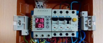
The process of assembling the second panel with three Barrier voltage control relays is shown:
2 – Three-phase voltage control relay based on Barrier relay
This is how this shield is connected:
2 – Connecting the voltage relay to the gap after the meter
This connection is very important because all power to the office goes through it. Therefore, I made it through screw-type terminal blocks (clamps).
The blue wires that previously went to the switch terminals now go through the terminals to the voltage relay panel. And from the Barrier outputs, the wires are connected directly to the switch terminals.
The connections in the panel are shown in the photo:
2 – Connections in the panel of the three-phase voltage control relay
The input cable carries three phases and zero. The current through the neutral wire is more than 100 times less than through the phase wires, so it can be neglected.
The second output cable uses three cores, the fourth is a spare (reserve).
As a result, the currents in the cables are the same, the cable is used at 75%, which is optimal from the point of view of overheating.
The second electrical panel took this form:
2 – Electrical control room with a new panel
A closer look at our shield:
2 – Panel with three-phase voltage control relay