Electric drive
An electric drive (abbreviated as Electric Drive) is an electromechanical system for driving the actuators of working machines and controlling this movement in order to implement the technological process. A modern electric drive is a combination of many electric machines, devices and their control systems. It is the main consumer of electrical energy (up to 60%) and the main source of mechanical energy in industry.
And at present, the electric drive is the main type of drive for stationary machines and mechanisms, and in many cases for irrigation, transport, agricultural and other mobile equipment.
Advantages of an electric drive:
I) the power of the electric motor to drive the working machine can be selected sufficiently close to the required one;
2) an electric engine is less dangerous in terms of fire than, for example, an internal combustion heat engine;
3) the electric drive allows you to quickly, and if necessary, often, start and stop the car, and smoothly brake it;
4) when the load on the shaft changes, the electric motor does not require special regulators for the supply of electricity from the network. The increase in electricity supplied to the engine occurs automatically with increasing load;
5) the electric drive allows you to select a type of electric motor whose mechanical characteristics are better suited than other motors to the characteristics of the working machine;
6) with an electric drive (by acting on an electric motor, converter or transmission), it is possible to stepwise or smoothly regulate the rotation speed of the working machine in the required ranges;
7) the electric motor is capable of overcoming long-term and significant overloads created by the working machine;
 the electric drive allows you to obtain the highest speed and highest productivity of the working machine;
 an electric motor allows you to save electricity, and in some cases, during regenerative braking, send it to the electrical network (in this case, mechanical energy is converted into electrical energy)
10) with an electric drive, it is possible to automate machines and installations more simply and completely;
11) the electric motor has higher efficiency. compared to other types of engines;
12) electric motors are produced with a high degree of balance, which allows them to be built into working machines, to lighten the foundation, and sometimes to completely abandon the foundation.
Modern electric drives are usually automated. An automatic electric drive control system allows you to construct a technological process in the most rational way, increase labor productivity, improve product quality and reduce its cost. Currently, the industry produces excavators, continuous transport mechanisms, lifts and other construction machines and equipment equipped with electric motors, electrical equipment, electric lighting and largely automated. Mechanical technicians need to have a good knowledge of electrical engineering, the properties and circuitry of electric motors, apparatus and instruments, the basics of an electric drive, electric drive control circuits and its automation, as well as the electrical equipment of irrigation and drainage machines.
Online electrical magazine
Systematization of electric drives is usually done according to the type of movement and maneuverability, the type of electronic and mechanical transmission devices, and the method of transmitting mechanical energy to the executive bodies.
According to the type of movement, electric drives of rotational and translational unidirectional and reverse motion, as well as electric drives of reciprocating motion, are distinguished.
According to the principle of regulating the speed and position of the executive body, the electric drive can be:
- unregulated and variable speed;
- tracking (using an electric drive, the movement of the executive body is reproduced in accordance with an arbitrarily changing master signal);
- software-controlled (the electric drive ensures the movement of the executive body in accordance with this program);
- adaptive (the electric drive automatically provides the best mode of movement of the executive body when the criteria for its operation change);
- positional (the electric drive provides regulation of the position of the executive body of the working machine).
Based on the type of mechanical transmission device, a distinction is made between a geared electric drive, which contains one type of mechanical transmission device, and a gearless drive, in which the electric motor is specifically connected to the actuator.
According to the type of electronic converting device, they are distinguished:
- valve electric drive, the converting device in which is a thyristor or transistor electricity converter;
- the controlled rectifier-motor system (UV-D) is a constant-current valve electric drive, the converting device of which is an adjustable voltage rectifier;
- system frequency converter - engine (FC-D) - AC valve electric drive, the converting device of which is an adjustable frequency converter;
- the generator-motor (G-D) and magnetic amplifier-motor (MU-D) system is a controlled electric drive, the converting device of which is, respectively, an electric machine converting unit or a magnetic amplifier.
According to the method of transferring mechanical energy to the executive body, electric drives are divided into group, personal and interconnected.
A group electric drive is characterized by the fact that from one motor several executive bodies of one or more working machines are driven through the box.
The kinematic chain in such a drive is complex and cumbersome, and the electric drive itself is uneconomical, making its operation and automation of technological processes more complicated. As a result, the electric transmission drive is practically not used at the present time; it has given way to a personal and interconnected one.
A personal electric drive is characterized by the fact that each executive body of the working machine is driven by its own separate engine. This type of drive is currently the main one, because with a personal electric drive, the kinematic transmission is simplified (in some cases it is completely eliminated) from the motor to the executive body, the technological process is simply automated, and the service conditions of the working machine are improved.
Personal electric drives are widely used in various modern machines, for example: in complex metal-cutting machines, rolling mills of metallurgical production, hoisting and transport machines, robotic manipulators, etc.
An interconnected electric drive contains two or more electrically or mechanically interconnected personal electric drives, during the operation of which a given ratio or equality of speeds, or loads, or the position of the executive bodies of working machines is maintained.
The need for such a drive appears due to design or technological considerations. An example of a multi-motor interconnected electric drive with a mechanical shaft is the drive of a long belt or chain assembly flow, the drive of the platform of the turning mechanism of a massive excavator, the drive of the common gear of a massive screw press.
In this case, when in an interconnected electric drive there is a need for a constant speed ratio of working bodies that do not have mechanical connections, or when the implementation of mechanical connections is difficult, a special electronic connection circuit of two or more electric motors is used, called an electronic shaft circuit.
An example of such a drive is the drive of a complex metalworking machine, the electric drive of locks and drawbridges, etc. The interconnected electric drive is widely used in paper making machines, textile units, rolling mills of metallurgical production, etc.
According to the level of automation, electric drives can be divided into non-automated, automatic and automatic. The last two types of electric drives are used in the vast majority of cases.
Miroshnik A. I., Lysenko O. A.
Electrician school
Electric drive of the assembly flow
Recommendations for choosing the type, type and power of the electric drive motor
When operating an electric drive with a long-term constant load, the task of choosing an electric motor (DC, asynchronous, synchronous) is relatively simple.
For an electric drive that does not require speed control over large speed ranges, it is recommended to use synchronous motors. This recommendation is explained by the fact that a modern synchronous motor starts up as quickly as an asynchronous one, and its dimensions are smaller and its operation is more economical than an asynchronous engine of the same power (a synchronous motor has a higher power factor cosφ and a higher maximum torque Mmax on the shaft).
At the same time, the latest generation of asynchronous motors can quite effectively regulate the rotation speed and reverse with the necessary torque for the operation of the electric drive, but special control devices are used for this.
But if the drive electric motor must operate under conditions of controlled rotation speed, reverse, frequent starts, large load changes, then when choosing the type of motor it is necessary to compare the operating conditions of the electric drive with the mechanical characteristics of various types of electric motors.
In electrical engineering, it is customary to distinguish between natural and artificial mechanical characteristics of a motor. The natural characteristic corresponds to the nominal (operating) conditions of its activation, the normal connection diagram and the absence of any additional elements in the engine circuits and the connection of these circuits according to special circuits.
An important criterion for assessing the mechanical characteristics of an electric motor is their rigidity:
where: ΔM - change in torque on the motor shaft;
Δn—change in engine rotor speed.
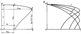
Depending on the value of rigidity, it is customary to divide mechanical characteristics into absolutely rigid, Δn = 0,λ = ∞ (synchronous motors), rigid, in which the change in rotational speed is small λ = 40 ÷ 10 (the linear part of the characteristic of an asynchronous motor, the characteristic of a DC motor with parallel excitation), soft with a large change in rotational speed, for which λ ≤ 10 (characteristic of a DC motor with series excitation, artificial characteristic of an asynchronous motor with a wound rotor, artificial characteristic of a DC motor with parallel excitation).
In Fig. 1 shows the natural mechanical characteristics of various types of engines.
Requirements for the rigidity of the mechanical characteristics in some cases are the basis for choosing the type of engine.
With frequent starts and variable loads, the most reliable, economical and easy to operate is an asynchronous motor with a squirrel-cage rotor. At high powers, if it is impossible to use a squirrel-cage asynchronous motor, an asynchronous motor with a wound rotor is installed.
A DC motor is more complex in design (due to the presence of a commutator-brush assembly), costs more, requires more careful maintenance and wears out faster than an AC motor. However, in some cases, preference is given to a DC motor, which allows simple means to change the rotation speed of the electric drive within a wide range.
The engine type (its design) is selected depending on environmental conditions. It is necessary to take into account the need to protect the environment from possible sparks in the engine (in the presence of an explosive atmosphere), as well as the engines themselves from the ingress of moisture, dust, and chemicals from the environment.
In many drive applications, it is necessary to regulate the rotation speed of the motor rotor.
There are two reliable, but significantly imperfect methods for regulating engine speed:
- inclusion of resistors in the circuit of the rotor armature windings;
- switching the number of pole pairs of the stator winding.
The first method is rational only with narrow control limits at a constant torque on the motor shaft, while the second provides only discrete (step) control and is practically used mainly for low-power drives.
Currently, thanks to the advent of high-power semiconductor devices, the situation in this area has changed significantly. Modern electronic converters make it possible to change the frequency of alternating current over a wide range, which allows you to smoothly regulate the speed of the rotating magnetic field, and therefore effectively regulate the speed of rotation of asynchronous and synchronous motors.
The optimal choice of electric motor power for the drive must satisfy the following requirements:
- reliability in operation;
- possibility of working condition in various conditions;
- economical in operation.
Installing a motor of greater power than is necessary under the operating conditions of the drive causes unnecessary energy losses during operation of the electric machine, causes additional capital investments, and an increase in the weight and dimensions of the motor.
Installing an electric motor of lower power reduces the performance of the electric drive and makes its operation unreliable. In this case, the electric motor itself may be damaged under such conditions.
The electric motor must be selected so that its power is used as fully as possible. During operation, the engine should not heat up to the maximum permissible temperature, at least for a very short time. In addition, the engine must operate normally under possible temporary overloads and develop the starting torque on the shaft that is required for the normal functioning of the actuator.
Accordingly, the engine power is selected in most cases based on heating conditions to the maximum permissible temperature. The so-called heating power selection is made. Then the compliance of the engine overload capacity with the machine starting conditions and temporary overloads is checked. Sometimes, with a large short-term overload, it is necessary to select a motor based on the required maximum power. In such conditions, the maximum engine power is usually not used for a long time.
Power selection for continuous duty drives with constant or slightly varying shaft loads is simple. In this case, the motor power should be equal to the load power, and checks for overheating and overload during operation of the electric drive are not necessary (this is explained by the initially determined operating conditions of the electric motor). At the same time, it is necessary to check whether the starting torque on the motor shaft is sufficient for the starting conditions of the given electrical machine.
Continuous load power is determined on the basis of theoretical calculations proven in practice.
Let's look at a specific example. For example, the motor power for a fan (and not only it, but any motor) can be determined as
where: V is the amount of forced air, m3/s2;
Δр—pressure drop, Pa;
ηven is the efficiency factor (efficiency) of the fan (for impeller fans it is 0.2 ÷ 0.35);
ηtrans is the efficiency of transmission from the engine to the fan impeller.
In the above formula, the product VΔр represents the useful power of the fan, and 1000 is the coefficient for converting power into kilowatts.
In engineering calculations, to determine the power of a drive electric motor during prolonged operation, electrical (obtained experimentally) formulas, tested by long-term practice, are used.
In short-term, intermittent and long-term operating modes of an electric drive with a variable load, it is important to know the law of change over time in the excess of the motor temperature above the ambient temperature.
From the point of view of heating, an electric machine is a very complex body. Nevertheless, in engineering calculations that do not require great accuracy, an electric machine can be considered a homogeneous body.
This makes it possible to apply a simplified heating equation to it:
where: C is the heat capacity of the electric machine;
H is the heat transfer of the machine;
Q0 is the heat released in the machine per unit time.
Let's consider two extreme cases: t = ∞ and t = 0. For t = ∞ we obtain: Qodt = HVmaxdt. (4)
Solving this equation by the method of separation of variables, we obtain
where is the heating time constant of the machine, determined experimentally.
At t = 0, the initial temperature rise will be V = V0, on the basis of which the constant A = Vmax - V0, and the law of increase in the temperature rise of the machine will have the form
Thus, the excess of the machine temperature V over the ambient temperature increases according to an exponential law, tending to the value Vmax. The value of the initial temperature rise V0 only changes the rate of temperature increase without changing the nature of the process (Fig. 2).
At different values of continuous load of the same machine in the range of electric motor powers (P1, P2, ... Pnom, ... Pk, ... Pn), the V(t) graphs will differ only in ordinates (Fig. 3).
The highest permissible temperature rise for a given machine is Vnom. A straight line parallel to the abscissa axis Vnom intersects at various points of the V(t) curves corresponding to different values of the electric motor load.
The abscissa of the intersection point determines the time period tk during which the engine power can be temporarily equal to the power Pk, which represents an overload in relation to its rated power in continuous operation. The heating curve, asymptotically approaching Vnom after a time interval tn, corresponds to the rated power of the electric motor Pnom. At loads less than Rnom, the engine power is not fully used. However, if the engine is loaded to rated power only for a relatively short time, then in fact it is also not being used at its full capacity. It is advisable to overload it for a short time, and the shorter the duration of operation, the greater this overload should be. The limit for increasing the motor load as the operating time decreases is determined by the instantaneous overload power of the motor, depending on its electromagnetic, mechanical and switching properties (maximum torque on the shaft for an asynchronous motor, switching conditions of the brush-commutator unit for DC machines, etc.) .
In intermittent mode, the electric motor alternately heats up and cools down. The change in its temperature during each “on-off” cycle depends on the previous thermal state.
A graph of the heating and cooling of the machine versus time under similar conditions is shown in Fig. 4.
The final temperature rise of any given part of the cycle is the initial temperature rise for the subsequent part of the cycle. If during one or another part of the cycle there is a noticeable change in the cooling conditions of the electric machine (motor stop or significant change in the rotor speed), then this changes the value of the machine heating time constant τ, which must be taken into account when constructing graphs.
The considered methods for determining the power of an electric motor based on temperature conditions by constructing heating graphs require a significant investment of time and labor-intensive analytical calculations. At the same time, the graphical method itself contains systematic errors and ultimately does not give accurate results. The graphical methods are presented above only to clearly show the picture of changes in engine heating under variable load.
In most cases, for such a choice of electric motor power, simpler, so-called engineering calculations are used, in particular the equivalent current. The equivalent current method is based on the assumption that with a variable motor load, its average losses should be equal to the losses at a continuous (nominal) load.
As is known from the theory of electrical machines, the engine power loss consists of constant Rpost and variable Rper powers. The power of constant losses is equal to the sum of the power losses due to friction, in the magnetic circuit (for asynchronous motors and DC motors with parallel excitation), for excitation in synchronous motors and motors with parallel excitation. The power of variable losses can be considered proportional to the square of the operating current I of the motor and the resistance of the corresponding winding r, and the latter can be approximately considered constant. If the current changes over appropriate periods of time, then over the entire working time Σt=T the total energy losses in the motor will be equal to
With a variable load of equivalent current Iek, for the same operating time of the electric motor T, energy losses in the motor are calculated using a simpler formula:
Knowing the equivalent current, rated voltage and rated power factor, you can determine the rated power of the motor:
The equivalent current method can be used only if the power losses in the magnetic core and friction, as well as the resistance of the windings, are constant throughout the entire working time T.
In some cases, the load conditions determine the direct torque required from the motor rather than the current. Then you can use the equivalent torque method: for all electric motors, the torque on the shaft is proportional to the product of current and magnetic flux. For AC motors (synchronous and asynchronous), the power factor cosφ can be approximately considered constant.
With such simplifications, we can consider the torque
where Kvr is a constant value, from which, from the above expression for the equivalent current Iek, one can obtain:
Next, based on the equivalent torque and rated angular speed of the motor ωnom, the rated power of the electric drive motor is calculated:
To increase the reliability of the electric drive, it is recommended to check whether the maximum torque Mmax of the motor is sufficient to meet the requirements of short-term possible overloads of this drive; in other words, the following condition must be met: the motor overload factor λnom must be greater in absolute value than the ratio of the maximum load torque Mmax to the rated torque of the motor, that is
At this point, the choice of engine type, type and power can be completed.
M. S. IVANOV, V. N. DRACHKOV, St. Petersburg State University of Civil Aviation (SPbSUCA).
Literature
- A. S. Kasatkin, M. V. Nemtsov. Electrical engineering: study. manual for universities. — 5th edition, revised. - M.: Energy, 2003.
- V. Yu. Lomonosov and others. Electrical engineering. M.: Energoatomizdat, 1990.
- G. G. Kudryavtsev and others. Microprocessors in maintenance systems for communication and control equipment - M.: Radio and Communications, 1999.
- V. N. Drachkov, V. V. Panferov. Electrical and Electronics. Part 1 Electrical engineering. Tutorial. Academy of Civil Aviation, 2006
- V. N. Drachkov, V. V. Panferov. Electrical and Electronics. Part 2 Electrical engineering. Tutorial. Academy of Civil Aviation, 2004
