Before the development of microprocessor technology, various relay systems were used to protect substations with voltages above 1000 volts. They consumed a huge amount of energy for their own needs, were difficult to set up and were not reliable. Today, this task is performed by logical bus protection systems built on electronic components.
Protection and automatic input
Relay protection and automation
Relay protection and automation is a system designed to protect a substation from emergency operation. It is a complex complex of electrical and electronic devices. Relay protection and automation continuously monitor the state of the network and, if necessary, make various switches in it.
Any RZiA has selectivity (selectivity). Those. it turns off exactly that section of the power system where an abnormal or emergency operation has occurred. Accordingly, some consumers remain without voltage, and not all at once. This is especially necessary in cases where shutdown implies a violation of technical regulations. processes of enterprises accompanied by the risk of emergency situations or financial losses.
Relay protection is also characterized by its speed. This property refers to the time spent disconnecting the damaged section of the line. Speed is closely related to selectivity. The setting for the permissible time for an emergency to occur is taken into account in the settings of the relay protection and automation terminal, and it determines on which section the line will be separated from the general system.
Additional Information. The speed of protection is its most important characteristic. For proper tuning you need a golden mean. If the time delays are chosen so that they are too short or long, then the system will disconnect lines that do not need it, i.e. False positives will occur.
RZiA terminal
Differential protection of transformers RZL-05.T2, RZL-05.T3
Wide range of protection and automation functions
Digital Oscilloscope Event Log
Integration into SCADA systems
Operating temperature -40°C. +55°C
Possibility of programming logic (on request)
Purpose
Microprocessor relay protection and automation devices of the RZL-05.T are designed to perform the functions of the main protection of a two-winding ( RZL-05.T2 ) or three-winding (or two-winding with a split winding) ( RZL-05.T3 ) transformer or autotransformer with a higher voltage of 35- 110 kV.
The devices are intended for installation in relay compartments of KSO, KRU, KRUN, as well as on panels, in control cabinets of power plants and substations of 35-110 kV.
Download detailed description of RZL-05.T
Functions
- Two stages of longitudinal differential protection - differential current cut-off (DTO) and sensitive differential current protection (DTZ) with braking from through current and detuning from magnetizing current surges (with blocking at the second, third and fifth harmonics during a magnetizing current surge). The DTO works without any blocking and has no braking. For the DTZ stage, braking is performed from all phase current channels.
- Monitoring the health of current circuits (CTC). For timely detection of faults in differential protection current circuits, for example, due to insulation failure or incorrect connection of current circuits, an unbalance alarm is provided in the differential protection arms.
- 5 stages of maximum current protection, incl. current cut-off (TO) and transformer overload protection (TOP) with independent and dependent time-current characteristics, with blocking against magnetizing current surge, with selection of operation in the direction of power. It is possible to implement a combined start based on current and minimum voltage (voltmeter blocking) for MTZ stages.
- Logical busbar protection (LBP) for quick shutdown of the LV HV circuit breaker when a fault occurs on the busbars.
- 3 stages of protection against ground faults in transformer HV circuits based on the measured and calculated zero-sequence current 3I0 of the HV side.
- Protection against open-phase mode (OPF) for negative sequence current.
- External (gas) protection of the transformer. The gas protection of the transformer is triggered by signals from the assigned discrete inputs and acts on the trip relay or alarm.
- Arc protection (AgP) with VOD sensors with the ability to control current.
- Breaker failure redundancy (CBF).
- Freely programmable logic (FPL), which allows you to freely program all discrete inputs, outputs and LEDs of the device.
- Non-volatile event log (256 events).
- Emergency oscilloscope. When the protection is triggered, the device records instantaneous values of input analog (user-selectable) and discrete signals (input, output, signs of protection operation).
- Temperature control inside the device.
- Monitoring the status of the device's discrete inputs.
Braking characteristic of differential protection
The response characteristic (braking characteristic) determines the ratio of differential (Idiff) and braking (Irest) currents. Broken line A-B-C-D
divides the plane into two parts - the area of operation and non-action.
Everything that lies above the broken line is a trigger area
.
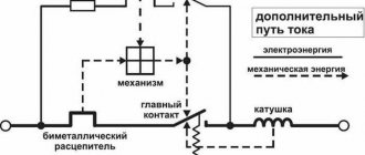
What does LZSH consist of?
Differential protection
Answering the question “What is LZSh protection?”, we can say that it includes a complex set of hardware and software designed to disconnect the line during abnormal operation. All of them can be divided into 3 categories:
- Sensors are devices that read information about the state of the power system in real time. For example, current and voltage on power buses, frequency, phase shift and cosph of the load, as well as the temperature of transformers, ambient air and similar indicators. All this information goes to the controller.
- Microprocessor terminals are the computing organ of the system. It would be a stretch to call it a computer. Externally, it is a small box with a screen displaying the network status and many buttons for setting up the device and its interaction with a person.
- Executive bodies - by analogy with a PC, these are peripheral devices. These include high-voltage switches, fans and pumps of cooling systems, and various drives for switching devices.
Simplified, it all works as follows. Some emergency situation occurs on the substation buses, for example, a short circuit. Current transformers register a critical excess of this parameter. From them the signal is transmitted to a microprocessor terminal, which processes it. This takes into account the short circuit current, its duration and a number of other characteristics. Then the terminal sends a signal to the actuator - a vacuum switch, which disconnects the section of the line affected by the short circuit.
Current transformers
Application
Despite some disadvantages, undervoltage protection is closely related to production processes and ensures reliable operation of technical equipment.
It is used to provide protection at power plants, ensuring the operation of important mechanisms in the event of a short-term loss of its own power. It is installed in problem areas of the power grid and substations, first disconnecting consumers of the third category. Ensures that voltage is maintained at vital facilities (hospitals, railways, communications, water supply, sewerage).
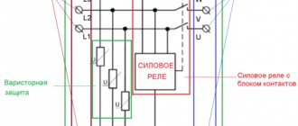
LZSH organization schemes
Arc protection
Most logical bus protection systems are implemented in a serial or parallel circuit. Each of them has its own advantages and disadvantages, but the principle of operation of the LZSh is similar in both cases.
In a series circuit, the individual contacts follow each other. While all of them are closed, a signal is sent to the LZSh blocking input, preventing the protection from triggering. If at least one contact of the relay terminal opens, the overall circuit will be broken.
Sequential LZSh circuit
In the case of a parallel circuit, the contacts are initially in the normally open position. For the LZS to operate, it is also necessary that one of them changes its state, i.e. closed up.
Parallel LZSh circuit
Behavior of LZSh during external short circuit
Overcurrent protection
The operating principle of logical bus protection is based on cutting off the line when a short circuit current occurs in it. In this case, it is assumed that the short circuit occurred somewhere outside the substation. While the line is in normal operating mode, the LZSh contacts generate a blocking signal. It prevents the protection from tripping, so the system is energized. As soon as a short circuit or serious overcurrent occurs, the LZSh contacts open. The protection is turned on. The calculation of the line shutdown time directly depends on the intensity of the short circuit and the settings made by the installer in the relay protection and automation terminal.
Additional Information. Intermittent short circuits are possible on overhead power lines. They can be caused by overlapping wires due to wind. In this case, the short circuit is short-term; after it disappears, the line is put back into operation by an automatic reclosure device (AR).
Relay classification
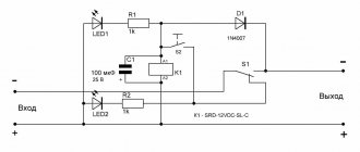
According to SIPs, the control relay is connected directly to the electrical circuit and is intended for private connections. It is one of the most common electrical products and is widely used as components.
Relay classification is carried out according to several different criteria, namely, such as:
- By purpose;
- Operating principle;
- The measured value;
- Power control;
- Response time.
The protective relay is used to turn on and off the protection of devices - fans, electric motors and other devices with thermal contacts. The protective device may automatically switch off if the contacts become open. Turning on the mains power again is possible only after the engine has cooled down well to the required temperature.
According to the principle of influence, the device is divided into:
- Electromechanical;
- Induction;
- Magnetic;
- Electronic;
- Photoelectronic.
Electrical relays are devices that activate one or several controlled electrical circuits when exposed to certain electrical signals. The most common are electromechanical relays, which are most often used in telemechanics, automation, and computer devices.
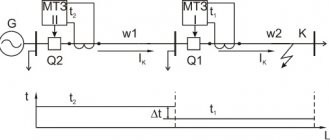
Operation of LZSh during short circuit on tires
Another purpose of using LZSh is to cut off the voltage when a short circuit occurs on the busbars. In this case, we are talking about a short circuit that occurs directly on the territory of a switchgear or substation. This situation has a peculiarity. The short circuit occurs in the immediate vicinity of the transformer. The tire resistance up to the short circuit point has a minimum value. The fault current will be extremely high, up to tens of thousands of amperes. The RZiA terminal, registering such a large value, will assemble a chain of LZSh faster than if the accident had formed somewhere far from the substation. If for some reason this protection cascade does not work, then the power will be turned off by the one that is higher in the chain. In this case, the entire section will be out of work. The response will be non-selective, which is undesirable.
Basic requirements for protective devices
So, in relation to relay protection and automation the following requirements are imposed:
- Selectivity. In the event of an emergency, only the area in which an abnormal operating mode is detected should be switched off. All other electrical equipment must work.
- Sensitivity. Relay protection must respond even to the most minimal values of emergency parameters (set by the response setting).
- Performance. An equally important requirement for relay protection and automation, because The faster the relay operates, the less chance there is of damage to electrical equipment, as well as danger.
- Reliability. Of course, the devices must perform their protective functions under the given operating conditions.
Reliability of LZSh
LZSh, from the point of view of performance testing, differs from other types of protection. It rarely works when tested by employees of measurement laboratories. This is explained by the fact that the LPS is assigned a less significant role; accordingly, it has a longer response time and simply does not have time to get ahead of other types of protection.
Most often, logical bus protection fails due to a short circuit of the current transformer or its turn short circuit. Fortunately, this happens quite rarely. In this case, the transformer is simply not able to correctly measure the current flowing through the bus it controls. Therefore, the LZSh protection blocking signal cannot be generated, which leads to its unintentional activation.
Important! Before disconnecting the wires from the current transformer, its terminals must be shorted together. Otherwise, a high-voltage potential may be induced in the CT winding, which is dangerous to the life of operating personnel and can lead to equipment damage.
LPS is a relatively simple and effective system for ensuring uninterrupted operation of the power system. Its use significantly reduces the negative consequences of emergency situations, and also significantly reduces the risk of their occurrence.
Relay classification
When considering this topic, one cannot help but dwell on the types of relay protection. Relay classification is presented as follows:
- Connection method: primary (connected directly to the equipment circuit) and secondary (connected through transformers).
- Execution options: electromechanical (a system of moving contacts disconnects the circuit) and electronic (disconnection occurs using electronics).
- Purpose: measuring (measure voltage, current, temperature and other parameters) and logical (transmit commands to other devices, carry out time delay, etc.).
- Method of influence: relay protection of direct influence (mechanically connected to the disconnecting device) and indirect influence (control the electromagnet circuit that turns off the power).
As for the types of relay protection systems themselves, there are many of them. Let’s immediately look at what types of relays there are and what they are used for.
- Overcurrent protection (overcurrent protection) is triggered if the current reaches the setting specified by the manufacturer.
- Directional overcurrent protection, in addition to the setting, the direction of power is controlled.
- Gas protection (GZ) is used to cut off power to the transformer as a result of gas release.
- Differential, scope of application - protection of busbars, transformers, and generators by comparing the values of currents at the input and output. If the difference is greater than the specified setting, the relay protection is activated.
- Remote (RD), turns off the power if it detects a decrease in resistance in the circuit, which occurs if a short-circuit current occurs.
- Distance protection with high-frequency blocking, used to disconnect overhead lines when a short circuit is detected.
- Remote with blocking via an optical channel, a more reliable version of the previous type of protection, because the influence of electrical noise on the optical channel is not so significant.
- Logical bus protection (LBP) is also used to detect short circuits, only in this case on buses and feeders (supply lines extending from substation buses).
- Dugovaya. Purpose – protection of complete switchgears (KRU) and complete transformer substations (CTS) from fire. The operating principle is based on the activation of optical sensors as a result of increased illumination, as well as pressure sensors when pressure increases.
- Differential phase (DPZ). Used to control phases at two ends of the supply line. If the current exceeds the setting, the relay is activated.