Selecting the type of protection
Transformers and autotransformers, in particular, as belonging to one of the subspecies, are reliable and structurally correct from the point of view of the fact that they do not contain rotating and moving parts. This avoids external impacts and chips that would damage the interior.
Also, using the block as the main structural element allows you to avoid movement of parts inside during a change of position or movement. But despite this, during operation it is impossible to completely protect the vehicle from disruption of stable operating conditions and internal damage. To avoid this problem, the equipment is provided with special relay protection.
Also, short phase circuits may occur in the design of the device. In this case, there may be actions between one phase located adjacent to each other, or between one or two to the ground. Problems related to the occurrence of short circuits between windings with different voltages and between turns of the same phase are also common. Short circuits also occur on the surface of busbars, on inputs and cables.
Of course, getting rid of short circuits and protecting against them will potentially protect professionals from injury associated with a current pulse. But, besides this, safety regulations say that protection of transformers is necessary to protect the mechanisms themselves from damage, fire, and surrounding objects from a fire-safe situation that may arise in the event of a breakdown.
The choice of means of protection depends on the existing problems. But in any case, the transformer is equipped with certain casings that are of a primary nature. The remaining means of protection are selected based on the power, design and typology of problems encountered in devices of this type.
Description and scope of differential current protection
Differential protection is the fastest acting for equipment. Thanks to its principle of operation, it has become possible to use it on any device, both those related to the type of conventional power vehicles and cars.
But despite the advantages, the schemes are not universal. They do not occur on all devices, but those that meet the following characteristics:
- single operating devices with power ratings from 6300 kV per A and more;
- functioning transformers arranged in parallel, with power ratings from 400 kVA.
Differential protection is also used if the device power is about thousands of kVA or maybe slightly higher, but the current cutoff, which is also installed as a protective screen, does not provide the required sensitivity. As for the last point, it is taken into account that the maximum shutter speed should be no more than 1 second. If the indicator is exceeded in a given vehicle, then differential protection is also taken into account.
The convenience of the circuit is that it can be used for parallel operation of devices. If we consider the reverse principle of operation, it turns out that when installing differential protection, not only rapid passage occurs, but also selective shutdown of the device.
Content
- 1. Initial data
- 2. Calculation of transformer differential protection settings
- 2.1 Calculation of differential cut-off settings (DZT-1)
- 2.2 Calculation of differential cut-off settings (DZT-2)
This article will consider the calculation of longitudinal differential protection of a transformer performed at the Sirius-T3 terminal (RADIUS Avtomatika JSC). The calculation was performed in accordance with the “Recommendations for the selection of settings for protection devices for transformers Sirius-T and Sirius-T3” by RADIUS Avtomatika JSC.
Kinds
Despite the fact that differential protection is a fairly popular method of protecting transformers, it cannot be used everywhere. This is due to the fact that the scope of activity extends to devices with limited power ratings.
Current cut-off
If a device, including an automobile transformer, operates at a power above 6,300 kV-A (single) or from 4,000 kV-A (multiple parallel), then the only convenient and rational method of protection is current cutoff.
The action is based entirely on the operating principles of current line cutoff. During a short circuit, the current at the inputs is significantly greater than on the load side. The cut-off current is selected depending on its operation during a short circuit - it should not operate.
The formula takes into account the indicators of the maximum current, which, passing through the inputs, is transmitted further, and the cutoff reliability coefficient (selected from the tabular data). Sensitivity is taken into account - it is characterized by a certain coefficient. This indicator is no less than two.
Gas
Another common method of protection is gas. It is used on various types of equipment, but only if there is oil cooling with expanders. They are required from a technological point of view for the operation of such devices:
- transformers and autotransformers with a power of 6,300 kVA and more;
- equipment with a power from 1000 to 4000 kVA, which are not equipped with cut-offs and differential protection;
- devices with the above indications, which have a maximum current protection characteristic of 1 second or more.
If a transformer with average power ratings already has another protection installed, for example, differential or cutoff, then using gas protection is not necessary. But if the device operates inside a workshop, its power exceeds 630, then gas protection is required, even if other types.
From overcurrents
A technique for protecting vehicles from overcurrents is also used. It turns off the power supply if there is damage to the internal part of the mechanism, including switches and tires.
Overload is usually symmetrical; to protect against it, maximum current protection in one phase is used. If the equipment is located in a serviced room, then the delay time is for the signal; in unserviced rooms - for unloading or shutting down. The type of installation depends on the number of windings. For two windings they are located on the main power side, and for three windings they are on the side of the winding where there is no power and on the power side. When operating options with three-way power supply, three devices are used on all sides.
Additional current transformers are required for protection against frame faults. It is inserted into the grounding bus between the circuit and the housing. At the same time, the current snout on the secondary is turned on.
It is worth paying attention to the fact that the protection mechanism is selected depending on the design features. The characteristics of power and current are also decisive.
BMRZ blocks
Differential is used as the main high-speed one. They are necessary to protect the terminals, the internal structural part. Connection to the BMRZ unit occurs according to the star circuit. This does not take into account groups and connection patterns.
The main thing is that the device ensures the supply of secondary currents in a positive direction (towards the device for which they are intended to protect against short circuits). A two-phase connection is made only if it is necessary to supply a common current pulse of phases A and C in antiphase in the triangle. Please note that:
- primary currents are out of phase, their values are not equal in the module;
- the shear angle depending on the variation in the connection of the primary and secondary;
- differences in coefficients lead to increased unevenness of secondary currents;
- limited use of intermediate devices is achieved due to leveling;
- phase rotation compensation is achieved by skewing the triangle.
If the short circuit is external, then the current flows only through the star-connected phases. If the winding is of the triangle type, then the currents move around the perimeter of the figure, while they are not present in the phases. Zero sequence currents are not taken into account in calculations.
There are two types of protection in DMRZ units: DTO and DZT. The first is stopped at the indicator of unbalance amplification in short-circuit mode, but in any case it is not always equal in terms of sensitivity coefficient. To achieve this goal, a DZT is used, which operates when a braking current is observed.
The calculation is carried out programmatically, taking into account the transformer’s own currents. The magnetizing current is only in the voltage-receiving winding. The block is installed separately for any circuit. In some cases, cross-blocking is more effective.
Selection of primary CTs and PTNs of BMRZ units
The CTs used must comply with the protection relay requirements. Issues of temperature stability are discussed separately. The following indicators are calculated:
- maximum phase current flowing through the device;
- minimum phase current;
- rated current coefficients;
- operating current is average.
The average knowledge of the maximum error of 0.1 is taken into account, if the current multiplicity is not more than the rated one, the same conditions apply to the load. Minimum error 0.5.
The setting is determined by the program if at max. It is not possible to select the PTN current value, then choose the option with a multiple of the primary current of 10 percent of the error and no more than 20 percent.
Differential current cut-off
DTO influences the configuration of equipment and the protection of various structural units. In particular, detuning is provided from:
- BTN;
- unbalance current.
The maximum value is taken from two possible values for triggering the cutoff. The standard indicator is selected at the level of four or five nominal coefficients.
When calculating the unbalance current, many characteristics are taken into account, including the detuning coefficient, the CT error coefficient during transition, the periodicity of the external pressure phase current, the maximum and minimum error values, relative errors and distribution currents.
Current differential protection with braking
Differential protection is calculated in a similar way. Relative errors are defined as half of the control range. Extreme coefficients are understood only if this does not affect the sensitivity characteristics.
Braking conditions will vary depending on the vehicle being used. If we are talking about two-winding, then the error coefficients are not taken into account; they are taken equal to unity. Be sure to consider the connection diagram of the windings and elements; only in this case is it possible to correctly calculate the circuits.
CALCULATION OF DIFFERENTIAL PROTECTION OF A TRANSFORMER AND TESTING OF DIFFERENTIAL RELAYS
Transcript
1 MINISTRY OF EDUCATION AND SCIENCE OF THE RUSSIAN FEDERATION FEDERAL EDUCATION AGENCY KURGAN STATE UNIVERSITY Department of Energy and Metal Technology CALCULATION OF DIFFERENTIAL PROTECTION OF A TRANSFORMER AND TESTING OF DIFFERENTIAL RELAYS Guidelines for performing laboratory work 7 in the course “Relay protection of power supply systems” for students of the specialty Kurgan 2007
2 Department: “Energy and technology of metals” Discipline: “Relay protection of power supply systems” (specialty) Compiled by: Associate Professor Shestakov D.N. Approved at the department meeting on August 31, 2006. Recommended by the university methodological council in 2007 2
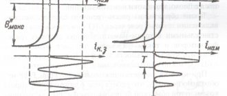
3 Laboratory work 7 TESTING DIFFERENTIAL RELAYS Purpose of the work: to expand and consolidate information about differential current protection of transformers, to become familiar with the purpose, principle of operation, design of a relay with a fast-saturating transformer type RNT-565 and a relay with magnetic braking type DZT-11, the work contains the choice of circuit and transformer differential protection parameters. General information DIFFERENTIAL RELAYS WITH A FAST-SATURATING TRANSFORMER Differential relays with a fast-saturating transformer of types RNT-565, RNT-566, RNT-567 are intended for use in differential current protection circuits of two- and three-winding transformers, autotransformers, generators and busbars. The RNT-560 series relay (Fig. 1) consists of an intermediate fast-saturating transformer T (BNT), an actuator KA (relay RT-40/0.2), a resistor R w for adjusting the operating current and a resistor R k for smoothly adjusting the detuning from aperiodic component. Relays of the RNT-560 series differ from each other only in the number of working windings. The magnetic system of the fast-saturating transformer BNT is made of three rods. On the middle rod there are primary windings, differential w d and two equalizing windings: w ur I and w ur II. The first section of the short-circuited winding w' to is also located here. on the outer rods there is a secondary working winding w 2 on the left and a second section of the short-circuited winding w "k on the right rod. The differential and equalization windings have branches and are sectioned. Changing the number of turns (every other) can be done using adjusting screws installed in detachable sockets. The numbers next to the sockets correspond to the number of turns included. The fast-saturating transformer is used to prevent the activation of protection from surges of magnetizing current passing through the differential circuit when the power transformer is turned on under voltage (no-load operation of the transformer), as well as from increased unbalance currents during transient conditions caused by external short circuits with significant aperiodity 3
4 dynamic current components. In these cases, the presence of an aperiodic component leads to the fact that the magnetic circuit is saturated, the resistance of the magnetization circuit decreases, and, consequently, the transformation of the periodic component of the current worsens, since it is closed mainly along the magnetization branch. Rice. 1. Relay device of type RNT-565 A short-circuited winding (w' to, w" to) is provided on the BNT magnetic circuit for better detuning of the actuator protection from transient conditions accompanied by the appearance of an aperiodic current component in the differential circuit. The degree of detuning, i.e., coarsening of the action of the output relay, can be changed by adjusting the resistance of the resistor Rk connected in series to the short-circuited winding circuit. With a decrease in Rk, the degree of saturation of the steel of the intermediate transformer increases and the reliability of detuning from transient currents with an aperiodic component increases, but the operating time of the relay during a short circuit in the protection zone increases by the attenuation time of the aperiodic component contained in the short-circuit current. Equalizing relay windings are used to equalize magnetic fluxes caused by currents passing in the differential protection arms. In protecting two-winding transformers, it is sufficient to use one equalizing winding. In protecting three-winding transformers, it is generally necessary to use both windings. 4
5 Regulation of the operating current of the relays under consideration is carried out by changing the number of turns of the differential winding. Since the parameters of the actuator do not change, the value of the minimum magnetic flux at which the relay reliably closes the contacts is constant. The magnetomotive force of operation, according to the plant, for relays of types RNT-565, RNT-566, RNT-567 is F a.s. = 100 ± 5 A and can be slightly changed using an adjustable resistor R w connected in parallel with the winding of the executive relay. The operating current of this relay with a sinusoidal current and normal adjustment of the counter spring (the relay motor is installed at the red line) is 0.17 A, and the voltage on the winding is 3.6 V. Due to the fact that F s.r. = I s.r. w d, the value of the operating current depends on the number of turns of the differential winding used, i.e. I s.r. = 100 / w d. (1) The value of the response current when only the differential winding is turned on can vary from 2.86 A (sockets 32, 3 are closed) to 12.5 A (sockets 8, 0 are closed). When two equalizing and differential windings are connected in series to a differential circuit, the operating current decreases (I average min = 1.45 A). So, for example, when turning on the relay according to the diagram in Fig. 2 terminals 4 6 (only one differential winding is turned on) and closed sockets at numbers 24 and 1, the relay operating current will be I s.r. = 100 / (24 + 1) = 4 A. If the relay is connected to the circuit with terminals 1 6 and a cover plate 2 4 is installed (two windings are connected in series), then the value of the relay operation current with the closed sockets indicated in the diagram will be I s.r. = 100 / ( ) = 2 A. Checking the MMF of relay operation is carried out according to the diagram shown in Fig. 2, by supplying current to the differential and equalizing windings. When using an autotransformer or load transformer in the circuit to obtain a sinusoidal shape of the current curve in series with the relay winding, it is necessary to include a resistor R, the minimum resistance values of which are given below: Number of turns of the primary winding R, Ohm 1,
6 Fig. 2. Test circuit and diagram of internal connections of the RNT-565 relay. Checking the sensitivity coefficient of the relay is most correctly and accurately carried out by measuring the current in the secondary winding of the BNT when the current in the primary winding changes using an executive relay as a current meter. This method is labor-intensive and requires changing the spring tension of the actuator relay. A convenient and practically quite accurate method is to determine the current sensitivity coefficient in an actuator relay. To carry out the work, the movable relay system is fixed (jammed) in the dropped position, corresponding to the open state of the contacts. Considering that saturation of the magnetic circuit of the BNT occurs at currents in the primary windings equal to approximately (4.5 5) I s.r., the secondary current is measured, i.e., the current in the executive 6
7 body I acting for MDS: F = F s.r. ; 2 F s.r. ; 5 F a.s. ; in this case, it is recommended to set the maximum number of turns of the working windings. The sensitivity coefficient is defined as the ratio of currents in the actuator at 2 F s.r. ; 5 F s.r. to current at F s.r., i.e. Ii. o.(2fs.r.) k h2 =. (2) Ii. o.(Fs.r.) Ii. o.(5fs.r.) k h5 = (3) Ii. o.(Fs.r.) For serviceable relays, the obtained values of the sensitivity coefficients should be: k h2 = 1.2 1.3; k h5 = 1.35 1.5. It is recommended to measure the current in the executive body with an electromagnetic ammeter type E513/4 at a limit of 0.5 A. DIFFERENTIAL RELAYS WITH MAGNETIC BRAKING Differential current relays with braking are used to increase the sensitivity of differential protection of transformers, autotransformers and generator-transformer units, i.e. in those cases , when the sensitivity of conventional differential current protection (without braking) is insufficient. A relay with magnetic braking of the DZT-11 type contains an intermediate fast-saturating three-rod transformer (Fig. 3) and an actuator in the form of an electromagnetic current relay of the RT-40/0.2 type. On the magnetic core of the intermediate transformer there are windings: a working RO on the middle rod, included in the differential protection circuit; equalizers for equalizing magnetic fluxes created by currents in the arms of differential protection (Fig. 3 shows one equalizing winding); brake maintenance consisting of two identical sections on the outer rods, included in one arm of the differential protection; the secondary VO of two identical sections, which supplies the executive body, is also located on the outer rods. 7
8 Fig. 3. Relay device of the DZT type The sections of the brake and secondary windings are wound and connected to each other so that the EMF induced by the magnetic fluxes of the brake winding in the circuit of the actuator are compensated (act counter-acting), and the EMF induced by the fluxes of the working winding act in accordance with, i.e. e. I rto = (E T1 E T2) / Z 2 = 0; (4) I ppro = (E P1 + E P2) / Z 2. (5) Thus, only the current passing through the working winding is transformed into the secondary circuit (into the winding of the executive relay). The current passing through the brake winding only causes magnetization of the outer cores of the magnetic circuit and changes the magnetic permeability. The degree of magnetization, and therefore the conditions for transformation of the current passing through the working winding, are determined by the MMF created by the current passing through the brake winding. In normal mode, the current passing in the differential protection arm is small and, therefore, the MMF created by this current with the help of the brake winding is small F T(n.r) = I T w T, the transformer operates in the rectilinear part of the magnetization characteristics. Since the unbalance current in this mode is also small, the EMF induced in the secondary circuit will not cause the actuator relay to operate. During an external short circuit, the current in the differential protection arm increases, the MMF determined by the brake winding increases, F T(k) = I K w T, which leads to saturation of the outer cores of the magnetic circuit. The magnetic resistance increases sharply, and the conditions for transformation of the unbalance current significantly worsen. Although the current is 8
9 unbalance in this mode increases, the executive relay will not operate; for its operation, more current must pass through the working winding of the transformer. Thus, with an increase in the current in the brake winding of the transformer, the current required to operate the executive relay automatically increases and the relay is coarsened (braked). In the absence of braking and normal adjustment of the executive relay, the MMF required for its operation is determined by the expression F s.r. = 100 ± 5 A. To achieve compliance of the operating relay operating current value with the specified MMF value without changing the spring tension, an additional resistor Rd is provided, connected in parallel to the executive relay winding. The location of the adjustment slide is marked on it by the factory when the relay is installed in a fixed position in the horizontal and vertical planes. When current passes through the brake winding of the transformer, the MMF required to operate the executive relay increases. Dependence of MMF response F a.s. from the MMF created by the current in the brake winding with normal (factory) tightening of the spring of the actuator relay, F brake is shown in Fig. 4 in the form of braking characteristics F a.s. = f (F brake). The upper curve corresponds to the condition that the currents in the working and braking windings are in phase (ϕ=0). At ϕ=90, the braking effect is less pronounced and the braking characteristic is located lower. Rice. 4. Braking characteristics of the relay type DZT-11 To regulate the relay operating current and compensate for the inequality of the MMF created by the currents in the protection arms, the working and equalizing windings are made with taps. The required number of turns is set with adjusting screws. The numbers next to the socket indicate the number of turned on turns. Similarly, turn on the required number of turns of the brake circuit 9
10 skeins. For relays of the DZT-11 type, the number of turns of the brake winding can be 1; 3; 5; 7; 9; eleven; 13; 18; 24. BRIEF METHODOLOGICAL INSTRUCTIONS FOR CALCULATING DIFFERENTIAL CURRENT PROTECTION OF A TRANSFORMER 1. When performing the calculation, it is necessary to take into account that the windings of the protected transformer are connected in a Υ / 11 circuit. This determines the connection diagrams of current transformers used in differential protection. It is necessary to understand the reasons for the appearance of individual components of the unbalance current during external short circuits and the definition of these components. 2. When drawing up a protection circuit, it is necessary to ensure that in normal mode and during external short circuits only unbalance current passes through the relay winding. 3. When calculating protection parameters, it is necessary to use the data in table. 1. Calculation of protection parameters with the RNT-565 relay is carried out in the following order: The protection operation current is selected. In this case, it is necessary to ensure that the protection does not operate in two modes of operation of the protected transformer: - when the transformer is turned on only from the power source side, when at the moment of switching on, significant surges of magnetizing current appear in the supply winding of the transformer. This current is closed through the relay coil. Therefore, to exclude the effect of protection, it is necessary to accept I s.z. = k ots I t.nom (6) - for three-phase short circuits outside the protection zone (damage on low voltage busbars), when the maximum through current of external short circuit I (3) k.in.max passes through the transformer. In this case, the maximum unbalance current kap kodn ε + U reg + f (3) Inb passes through the protection. calc. max = Ik. ext. max (7)
11 Parameter name Parameter value, options Table Rated power of the transformer S t.nom, MV A Voltage regulation range under load U reg, % Rated voltage U nom.sr on the HV and HV side LV, kV LV 6.6 38, .5 6 ,6 Maximum through current through the transformer during a three-phase short circuit, referred to the HV side I (3) k.in.max, A Two-phase short circuit current in case of damage in the protection zone, referred to the HV side in the minimum mode I (2) k.min , A Therefore, to exclude the effect of protection, it is necessary to accept I s.z. = k ots I nb.calc.max. (8) For the RNT-565 relay k ap = 1, and the error f is not taken into account as a first approximation. Since different types of current transformers are used in protection, they take K one = 1. The total error of current transformers is ε = 10%. Taking this into account, expression (8) for the protection operation current takes the form U reg (3) Iс. h. = kots 0.1 + Ik. ext. max 100. (9) Here U reg is the range of change in transformer voltage in one direction from the nominal value during regulation. Thus, the operation current is determined from expressions (6) and (9) at k ots = 1.3. The larger of the two expressions obtained is accepted as the calculated one. Next, a preliminary check is made of the sensitivity of the protection in the event of a two-phase short circuit at the terminals behind the transformer (short circuit in the protection zone) in the minimum mode. eleven
12 In this case, the entire fault current passes through the protection, and the sensitivity coefficient is determined by: (2) k. min I k h =. (10) I p. h. If k h 2, then the calculation should be continued, if less than 2, then it is necessary to apply differential protection with braking. It is recommended that further calculation of the protection parameters be presented in the form of Table 2. Calculation expressions for the sides Table 2 Name of the parameter High voltage Low voltage (HV) (LV) 1 Primary rated ST rated current of the transformer I t.nom, A I HV =. S 1 I T nom NN =. 1 3 U HV 3 U LV 2 Connection diagram of windings Υ of a power transformer 3 Connection diagram of current transformers Υ 4 Circuit coefficient k cx Calculated coefficient kсх I of transformation of current transformers K T.calculation KT. VN. p = 5 6 Current transformer coefficient K T., from the standard series (see note - T. VN = IK CT. No. 5 at the end of the table) 7 Secondary currents in the protection arms, at rated kсх II 1 2VN = KT. HV transformer power I 2nom, A 8 Relay actuation currents kсх II with RNT-565, I s.r., A s. R. ВН = К 9 The main side of protection is selected. VN 1VN. h. VN T. VN K T. NN. p K T. NN = II 2NN s. R. НН k = сх I 5 IТТ. nom 5 kсх I = K k = 1НН Т. НН сх I К 1НН с. h. NN T. NN Usually the main side is taken to be the side with a large operating current of the relay I s.r.osn (I s.r.vn or I s.r.nn) 12
13 10 Estimated number of turns of the NTT relay winding for the main side of the protected transformer 11 Accepted number of turns for the main side W main. 12 Estimated number of turns of the NTT relay winding for the non-main side W non-main.calc. 13 Accepted number of turns of the BNT relay winding for the non-main side 14 Component of the primary unbalance current I nb.calc.max. see expression (7), due to rounding of the calculated number of turns of the non-main side, I nb., A 15 Primary calculated unbalance current I nb.calc.max. taking into account I nb., A 16 Specified value of the relay operation current on the main side, A 17 Specified value of the protection operation current on the main side (A) Fс. R. Wosn. calc = ; Iс. R. main F s. R. = 100A End of table 2 W main. the number of turns Wmain IW 2main non-main is accepted that is the closest less in relation to W main.calc. calc = I2unosn Currents are taken from point 7, taking into account which side is taken as the main W unosn. the nearest integer f (3) Inb is accepted. = Ik. ext. max = 100 = ( Wunbase calculation Wunbase ) (3) Wunbase calc ( ε + U ) Iк. ext. max reg (3) I nb. calc. Max. = Ik. ext. max + Inb 100 Fs. R. Iс. R. basic = W basic Iс. R. basic KTT. main Is. h. = kсх Here K CT.main = K TT.VN (or K TT.LV), ak cx = 3 (or 1) depending on which side is taken as the main one 18 Actual detuning coefficient k ots I k s s ots =.. Inb. calc. max Here I nb.calc.max. taken from paragraph 15 Note. The calculated transformation ratios of current transformers K T.VN and K T.NN may differ from standard values. Therefore, after determining the coefficients according to point 5 of Table 2, it is necessary to select those closest to the calculated value from the following standard values: 10/5; 20/5; 30/5; 50/5; 75/5; 100/5; 150/5; 200/5; 300/5; 400/5; 600/5; 800/5; 1000/5; 1200/5; 1500/5; 2000/5; 3000/5; 4000/5; 5000/5; 6000/5. 13
14 The actual detuning coefficient must be at least 1.3; if k ots < 1.3, then a different number of turns W main should be adopted for the main side, less than that adopted previously (see paragraph 11). Then repeat the calculation point by point. The calculation is repeated until the actual detuning coefficient is approximately equal to or greater than 1.3, the resulting number of turns W main. and W unbasic. BNT windings are accepted for installation on the main and non-main sides (see Fig. 2) The value of the sensitivity coefficient is determined for the specified protection operation current, corresponding to the final accepted value (see paragraph 17), in the mode of a two-phase short circuit at the low voltage terminals. Determine the sensitivity coefficient using (10). It must be at least 2. Work order 1. Understand the features of differential protection of transformers, connection diagrams of current transformers, components of unbalance current. 2. Familiarize yourself with the principle of operation, design and adjustment of the RNT-565 relay; draw a diagram of internal connections, write down passport data. 3. Draw up a diagram of longitudinal differential protection of a transformer with a connection of windings Υ / 11, indicate the current distribution in it during a three-phase short circuit in the zone and outside the protection zone. 4. Carry out the necessary protection calculation according to the option specified by the teacher (see brief guidelines for calculating differential current protection of a transformer). 5. Using the adjusting screws, set the number of turns required by calculation on all windings of the intermediate transformer (in accordance with the calculation). 6. Having assembled the diagram according to Fig. 2, check the MMF response at different settings, first using only the differential winding, and then using the differential and equalizing winding together. To do this, at given positions of the adjusting screws, gradually increasing the current in the circuit, fix the minimum current value at which the relay contacts are reliably closed; this current value is the operation current; results for 14
15 be included in the table. 3. For each measurement, calculate the MMF response value F a.s. 7. Compare the experimental results with the data indicated in the reference literature; make a conclusion about the suitability of the relay for operation. Position of adjusting screws Measured values Table 3 w d, vit. w ur I, vit. w mouth = w d + w ur I, vit. I s.r., A F s.r. = I s.r. w mouth Test questions 1. How to configure a relay type RNT-565 for a given operating current? 2. Purpose of equalizing windings in relays of the RNT type. Is it possible to use equalizing windings without a differential winding in a relay of the RNT-565 type? 4. What is the sensitivity coefficient of relay type RNT-565? 5. How is relay type RNT-565 detuned from magnetizing current surges? 6. What causes a slight slowdown in the action of differential protection with a relay of the RNT type during a short circuit in the protection zone compared to a differential protection circuit with a current relay without a BNT? 565? 7. What is the purpose of resistors R w, R k in the circuit of a relay of type RNT-8. Is it permissible to operate a relay of type RNT-565 with an open circuit of a short-circuited winding? 9. What is the scope of application of differential current protection with braking? 10. What are the advantages and disadvantages of a relay with magnetic braking type DZT-11 compared to a differential relay type RNT-565? 11. What is magnetic braking and how is it achieved? 15
16 References 1. Guidelines for relay protection. Issue 13B. Relay protection of step-down transformers and autotransformers kv. Calculations. M.: Energoatomizdat, S. Plashansky L.A. Basics of electrical supply. Section “Relay protection of electrical installations” M.: Moscow State Publishing House. Mining University, S Berkovich M.A. and others. Fundamentals of relay protection technology. M.: Energoatomizdat, S. Andreev V.A. Relay protection and automation of power supply systems. M.: Higher School, With Protection Relay. M.: Energy, S. Kamnev V.N. Practical work on relay protection and automation. M.: Higher School, S. Barzam A.B., Poyarkova T.M. Laboratory work on relay protection and automation. M.: Energy, S
17 Shestakov Dmitry Nikolaevich CALCULATION OF DIFFERENTIAL PROTECTION OF A TRANSFORMER AND TESTING OF DIFFERENTIAL RELAYS Methodological instructions for performing laboratory work 7 in the course “Relay protection of power supply systems” for students of the specialty Editor N. L. Popova Signed for publication Format 60x84 1/16 Paper type. 1 Screen printing Conditions of printing l. 1.25 Academic ed. l. 1.25 Order Circulation 100 Free price Editorial and Publishing Center of KSU, Kurgan, st. Gogol, 25. Kurgan State University. 17
General principles for selecting DZT settings
When it is necessary to reduce the unbalance component, BMRZ blocks with separate characteristics are used. These include taking into account the position of the device. There are types:
- rude;
- sensitive.
The first type of installation includes all average regulatory provisions (up to half the deviation). For sensitive ones, variations with deviations of no more than 5 percent from the original indicator are chosen. Sensitivity increases if you reduce the current when calculating the position of the transformer.
The selection principle is to find the correct switching group. The conditions for using the blocks are given in the instructions for the devices. Modern options switch automatically, while the unit itself is responsible for sending the signal. It is important to carry out such actions as setting the primary current, setting the unbalance signal.
Selecting the setting for the initial operating current of the DZT
At this stage, the detuning conditions become an important characteristic. They are calculated from the maximum unbalance current when the load is on. Accounting occurs in two switch modes. The data is checked once for the coarse type, and the second for the sensitive type. Afterwards, the indicators are summed up and the statistical average is calculated.
The current readings vary depending on the number of winding layers. For two-winding or three-winding options, the current indicators will be different.
Selecting the braking coefficient setting for the second section, characteristics
This coefficient is calculated using the formulas for detuning conditions depending on the nominal unbalance current, which appears with the braking current at the end of the last section.
The type of sensitivity of the installation is taken into account - calculations are carried out twice. Rough is taken if voltage regulation in the sources does not occur and has no effect. Typically, for calculations, a value equal to the minimum input is accepted.
Selecting the third section braking coefficient setting, characteristics
Here, the conditions for detuning the operation from the unbalance current under conditions of maximum short-circuit indicators are taken into account. For the calculation, data is required on the error magnification factor (it is taken as standard equal to 2.5), phase current, maximum error, and rated secondary current pulse.
Checking the sensitivity of the DZT
Sensitivity is calculated at the terminals when operation is carried out in the usual mode on the branch. According to standards, the coefficient should not exceed two. But in some cases the reduction is impossible for technical reasons. The value is taken to be 1.5 or so if:
- power characteristics at the terminals of the lowest device are less than 800 mVA;
- if there is no power supply to one of the sides;
- when energized on one side;
- in short circuit mode behind the reactor.
If other protective mechanisms are present, then it is permissible not to use it. All attention is paid to the sensitivity coefficient and the possibility of excluding the device is judged by its features. The coefficient is calculated if the mineral value of the imbalance is more than a tenth of a unit.
Unbalance Alarm Setpoint Selection
The criteria are selected in such a way that the coefficient is within reasonable limits. The detuning coefficient indicators are taken into account (additional 10-20 percent are invested), as well as the maximum temporary reserve indicators.
Selection of DZT settings in the presence of TSN in the protection zone
The coefficient in this case will be equal to 1.5. The frequency of current flow through the phases and the indicators of the normal current that is supplied to the primary winding of the transformer are taken into account. Additionally, data on the operating current that occurs in load mode is considered.
Selecting the settings for blocking the DZT when a BTN occurs
It is necessary to take into account all the above instructions, but in addition, the instructions are supplemented by other points. Among them:
- cross-blocking should be used only in cases where it is required by the characteristics of the winding connection group;
- if it is possible to trace the reasons for the vehicle shutdown and eliminate them, then cross blocking is not used;
- if the identified cause is an unacceptable IPB value for carrying out the block, then turn on the equipment again.
The time setting is about one second for equipment of medium and low power, for large values the standard is 2 seconds.
Requirements for formatting calculation results
There are certain requirements for the design of settlement procedures. This allows calculations to be made in a way that is understandable for other radio amateurs and specialists who will use the information later if the situation requires it.
A special assignment form is issued. If we are talking about large-scale production, then authorized employees deal with this issue. If you do the calculations yourself, it is recommended to download the samples on the Internet. The form includes information about settings and keys. Specialists undertake to be guided by the schematic solutions that are presented in specific instructions.
Calculation examples
Double winding transformer
The solution to the problem begins with determining the indicator from the inrush of the magnetizing current and from the unbalance current. The first is equal to the product of the detuning coefficient and the data on the rated current of the vehicle. The value of the second is also the product of the safety factor and the unbalance current.
The negative position of the current is calculated, and the unbalance current includes the data of all. The coefficients of the aperiodic component and uniformity, three-phase short circuit are taken into account. Next it is calculated:
- relay operating current;
- number of turns of the HV winding;
- number of LV turns;
- protection sensitivity factor.
Two-winding transformer with split LV winding
A device with splitting of the low voltage winding is considered as two two-winding. In this case, a prerequisite is that they are powered from a common network.
The data is entered into the general scheme, the calculation is carried out according to an identical algorithm to the previous one. The only exception is the last stages, when the designation of the number of turns and the influence of the load on this is carried out.
Three-winding power transformer
Calculating the differential protection of a vehicle with three windings will take a little longer, since the coefficients for each circuit are isolated. The algorithm of actions is as follows:
- determination of primary rated currents for HV, MV and LV;
- determination of secondary rated currents, taking into account the type of connection;
- selection of working branches;
- calculating the estimated device unbalance coefficient using tabular data;
- determination of differential operating current;
- sensitivity of the braking indicator.
At the last stage, it is determined whether the conditions for comparing the operating current depending on the applied load are met. There must be more than two.
On step-down transformers
Step-down transformers also need a differential. protection as the other type. The calculation is carried out in a similar way, that is, first the currents and unbalance are calculated, and the coefficients are checked.
It is important to pay attention to the connected loads and their power ratings. When calculating step-down equipment, this is a prerequisite.
Differential protection based on RNT relays
Differential protection based on RNT relays
Relays with a saturating current transformer (SCT) and an electromagnetic relay are made according to a circulating current circuit. At the same time, the functions of NTT include:
- protection against false operation of the relay under the influence of unbalance current, a jump in which occurs during transient processes;
- compensation for the difference in secondary currents in the differential protection arms due to the design features of the measuring devices and external influences.
NTT design: three-rod magnetic core with a double cross-section of the middle rod compared to the outer ones. The primary windings are wound on the middle rod; on the middle and right - closed circuit windings; on the left rod there is a secondary winding acting on the actuator. All this is enclosed in a single housing, which includes a casing and a base.
The protection is activated (under the influence of short circuit current) when the rods reach a given induction value: 0.4 T for the right and middle rods and 1.2 T for the left rod.