Any household electrical appliance that operates in the home wiring is designed by manufacturers to be powered by a harmonic sine wave signal with a voltage of 220 or 380 volts.
Complex electronic equipment uses direct current rectified by special units.
When the shape and amplitude of the supply voltage changes, it greatly affects the quality of work of household consumers, reducing their service life.
Violations of technical standards for the electricity supplied to the house often occur within the household network. This issue is discussed in detail in an article devoted to the electrical safety of a private home and cottage.
The protection of household appliances must be given serious attention:
- implement a high-quality grounding system for the building with your own hands or by involving electrical specialists according to one of the regulatory schemes;
- ensure reliable operation of the potential equalization system;
- apply an additional potential equalization system in high-risk areas;
- use a voltage control relay that eliminates the impact of power failures from emergency situations from the power system;
- take care of external lightning protection of the house, capable of withstanding lightning discharges that cause enormous harm to the building and residents;
- counteract the penetration of lightning aftereffects into the electrical circuit of a household network, using devices with surge protection from surge protectors.
What are internal lightning protection devices intended for and how do they work during discharges?
The spontaneous occurrence of lightning occurs suddenly, creating enormous destruction.
External lightning protection, consisting of a lightning rod located above the roof, as well as a lightning rod and a grounding loop, allows you to protect your house from it.
The discharge current, penetrating as a short-term pulse through the prepared circuit, is very large. It induces overvoltage in nearby building wiring and conductive parts, which can burn insulation and damage household appliances.
Internal lightning protection devices, which are a set of technical devices and instruments based on SPD modules and connected to the grounding system, are designed to prevent the dangerous consequences of a lightning discharge.
They work reliably not only in the event of a direct lightning strike on the house, but also extinguish discharges falling into:
- power line supply;
- nearby trees and buildings;
- soil located next to the building.
If there are usually no issues with a blow to a power line, then in the last two cases the overvoltage can impulse penetrate into the home wiring along the ground circuit, water supply pipes, sewerage pipes, and other metal lines, as shown in the very first picture
The operation of internal lightning protection occurs by connecting the penetrating high-voltage pulse to a specially selected arrester or electronic element - a varistor.
It is switched on at the difference of two potentials and for normal voltage it has a very high resistance when the currents through it are limited to not exceed a few milliamps.
When an emergency pulse hits the varistor circuit, it opens the semiconductor junction, short-circuiting it. Through it, dangerous potential begins to flow to the protective grounding.
After the varistor, the dangerous voltage is significantly limited. Modern protection modules - SPDs - have been created on the basis of these electronic components.
Specifications
Here are the basic technical characteristics that you should pay attention to when choosing an SPD. They are usually written on the device body.
- rated and maximum network voltage
This is the voltage at which the device will operate normally without tripping. When it is exceeded, the SPD becomes active.
- rated and maximum discharge current
This is the current that the SPD can pass through itself several times without consequences and the risk of failure.
An SPD is not necessarily a disposable device, as some people believe.
- protective voltage level or classification voltage
The maximum U at the terminals of the device when the varistor begins to open when a certain current flows through it.
- device class
Surge protection device: how to choose and install the module correctly
Imagine a picture when the accumulated energy of static electricity between clouds moving over long distances is discharged by a lightning strike on a building or the power line feeding it.
The average shape of the current pulse is shown below. It first increases steeply for about 10 microseconds, and then, having reached its apogee, begins to gradually decrease. Moreover, the decrease to the middle of the maximum current value occurs after 350 μs and continues further until zero.
This lightning impulse creates an overvoltage in the network, which approximately follows the shape of the current, but may differ due to the operation of surge suppressors installed on overhead power lines.
The shape of such a pulse processed by spark gaps is shown a little to the right, and a conventional sine wave with a frequency of 50 hertz is below for comparison.
Power line surge suppressors operate by breaking through a calibrated air gap with an increased discharge pulse. In the normal state, its resistance prevents the flow of currents from a voltage of normal magnitude.
The limiters of high-voltage power lines are quite impressive in size.
On 0.4 kV overhead power lines their dimensions are significantly smaller. They are located on a support next to the insulators.
Overvoltage suppressors for overhead lines are capable of extinguishing very high lightning voltages only up to 6 kilovolts. Such a pulse has a modified voltage rise and fall shape with a characteristic of 8/20 μs. It goes to the input devices of your home.
Transmission line surge protection has greatly reduced and transformed it. But this is clearly not enough to ensure the safety of equipment and residents.
Household wiring 220/380 volts is produced with insulation capable of withstanding impulses of 1.5 ÷ 2.5 kV. Anything bigger breaks it. Therefore, it is necessary to use an additional surge protection device for a private home.
The range of such designs is extensive. They need to be able to select and install correctly.
SPDs for a 0.4 kV network are available for 2 possible emergency extinguishing modes:
- discharge current with a form of 10/350 μs, which did not change from the surge arrester of the overhead power line;
- overvoltage pulse with characteristic 8/20 μs.
Based on these factors, it is convenient when choosing an SPD to use the algorithm that I showed in the picture below.
However, one should imagine that there are practically no devices capable of one-time extinguishing a 6 kilovolt pulse to a value of 1.5 kV that is safe for household wiring.
This process occurs in three stages. Each of them uses its own class of SPD, although there are small exceptions to this rule.
Class 1 modules are capable of reducing an overvoltage impulse from 6 to 4 kV, which penetrates:
- after power line limiters;
- or induced by the lightning discharge current flowing down the lightning rod;
- or its impact on nearby buildings, trees, or soil.
Class 1 surge protectors are installed in the building's input panel inside a separate sealed fireproof cell. Neglecting this rule is dangerous.
During installation, the protected cables must be laid correctly. They should not intersect with the discharge of emergency currents to the ground circuit and incoming, unprotected highways.
The modules are protected from overcurrents by power fuses with fuse links.
Automatic switches are not suitable for these purposes. Their contacts cannot withstand the generated impulse overloads. They are welded, and the damage continues to develop.
The next class of SPD No. 2 reduces the overvoltage impulse from four to 2.5 kV. It is placed in the next distribution board in the hierarchy, for example, an apartment one. It complements the work of the previous module, but can also be used autonomously.
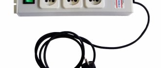
Class No. 3 surge protection devices can be made in modules installed on a DIN rail or in kits built into household appliances, extension cords, and surge protectors.
SPD of class 3 is capable of ensuring safety only after protection of class No. 2 is triggered. It is placed in series behind it because at 4 kilovolts it burns out.
Manufacturers are concerned about the complexity of choosing the correct SPD design and offer a comprehensive solution to this issue with a general module called 1+2+3.
It is placed in a separate box. However, the price of such a development is not affordable for everyone.
Varieties
In order to protect the home electrical network from any kind of overvoltage, including pulsed, the following types of devices are used:
- SPD.
The device primarily protects against high voltage surges, such as, for example, during a lightning strike. There are the following installation options:
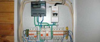
- Inside the input panel. Installed together with lightning protection of the house. Is the most reliable. If lightning strikes the house, the device will work like an automatic machine and protect all the equipment in the house. An option without a lightning rod is also allowed. But then you will need to install several different types of SPDs - one on a power line support, another on a pole next to the house, and another one on the panel of the house itself.
Installation of an SPD inside the input panel of a private house Source art-liga.rf
Surge protection: private house with single-phase power supply
Installation of electrical wiring in a private house, especially one made of wood and flammable materials, requires careful adherence to electrical safety rules.
It is necessary to take into account that the building can be powered using different grounding schemes:
- typical old TN-C;
- or modern, safer TN-S or its modifications.
Let's look at both cases.
SPD connection diagram: 2 options according to the TN-S grounding system
The picture below shows a detailed circuit with protection of combined class 1+2, which is used for installation after the input circuit breaker.
The surge suppressor varistor is built into the module housing and protects the electrical circuit from direct or remote atmospheric lightning discharges.
The signal flag, traditional for all SPDs, has two colors:
- the green position indicates that the device is working properly and is ready for operation;
- red - about the need for replacement in case of operation or burnout.
Such a module can be used in all grounding systems, not just TN-S. It has 3 connection terminals:
- top left L - phase wire;
- top right PE - protective grounding conductor;
- bottom N - neutral wire.
The SPD protects the electric meter and all circuits after it.
The next diagram shows an option for using protection with an RCD. After it, an additional working zero bus N1 is created, from which all consumers in the apartment are powered.
The scheme seems clear, there should be no questions.
For additional TN-CS and TT grounding systems, I propose two more schemes for study and analysis. They also have an SPD mounted in the input device.
I do not show the meter connection circuits, voltage control relays RKN and RCD, as well as consumers in detail. But the principle is clear: a PE protective bus is used.
But the old grounding system does not have it, which reduces reliability and safety. But it still provides protection, which is why it is considered.
SPD connection diagram using TN-C grounding system
The absence of a PE bus dictates the need to connect an SPD only between the potentials of the phase wire and PEN. There are simply no other options.
The method of installing protection for single-phase wiring is shown on the left, and three-phase wiring is shown on the right.
The overvoltage pulse is removed by the principle of creating an artificial short circuit in the supply circuit.
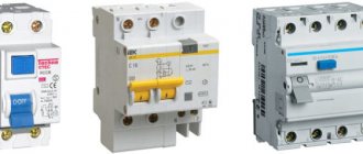
SPD classes
There are only three classes of devices according to the degree of protection:
- Class I device (overvoltage category IV) - protects the system from direct lightning strikes, and is installed in the main distribution board or in the input distribution device (IDU). It is imperative to use this device if the building is located in an open area and is surrounded by many tall trees, which increases the risk of lightning.
- Class II device (overvoltage category III) - used as an addition to a Class I device to protect the network from switching effects, i.e. from internal network overvoltage. Installed in the distribution board.
- Class III device (overvoltage category II) - used for protection against residual atmospheric and switching overvoltages, as well as to eliminate high-frequency interference passing through a class II device. Installation is carried out both in ordinary sockets or junction boxes, and in electrical appliances themselves that need to be protected.
Classification according to the degree of current discharge:
- Class B - air or gas discharges with a discharge current of 45 to 60 kA. They are installed at the entrance to the building in the main switchboard or in the input distribution device.
- Class C - varistor modules with discharge currents of about 40 kA. Installed in additional panels.
- Classes C and D are used in tandem if underground cable entry is required.
IMPORTANT! The distance between SPDs must be at least 10 meters along the length of the wiring.
Surge protection: private house with three-phase power supply
I analyze the principles of connecting SPDs using the example of different grounding systems.
SPD connection diagram for three-phase power supply at home using the TN-S system
Wiring protection is assigned to:
- three-pole input circuit breaker;
- single-pole and three-pole circuit breakers of outgoing lines;
- surge protection device of combined type 1+2+3.
Electricity metering is carried out by a three-phase electric meter. After it, an additional bus N1 is formed in the working zero circuits. All consumers are powered from it.
The N and PE busbars and the SPD module are connected in a standard way.
When using protection classes No. 1, 2, 3 separately, they should be distributed among zones I, II, III.
The penetration of overvoltage pulses from all sides of the phase potentials, working zero and equipment connected to the ground circuit blocks the inclusion of modules between the phase, neutral and PE buses.
SPD connection diagram: 2 options for three-phase power supply at home using the TN-C system
The proposed development does not show a pure option for connecting protections under the TN-C grounding system, but a modification of the transition to TN-CS recommended by modern requirements with re-grounding.
The PEN conductor is supplied through the power cable from the supply transformer substation to its busbar, which is connected by a jumper to the working zero assembly and the re-grounding busbar.
A three-pole SPD, connected after the input circuit breaker, protects the electric meter and all its circuits, including the RCD, from overvoltage pulses. I remind you that it must be mounted in a separate fireproof box.
In the absence of re-grounding, the lower terminal of the SPD module is connected to the PEN conductor bus with a separate core, and the wiring works purely according to the old TN-C system.
Another technique for reducing the rising edge of an overvoltage surge is shown below. Special reactances work here - chokes LL1-3 with an inductance from 6 to 15 microhenry, selected by calculation.
They are used when equipment is located close to each other to create a short delay in the response of the protection required by selectivity conditions.
They are mounted in a separate protective shield together with the SPD. This makes it easier to perform settings, periodic maintenance, and preventive maintenance.
I believe that it is necessary to point out one more option for using surge suppressors and arresters, which is sometimes neglected by owners of complex electronic equipment.
In certain situations, as was the case in my electrical laboratory at a 330 kV substation. The desktop computer was exposed to various types of exposure to electromagnetic fields with frequencies in the low and high ranges. This affected the display of information and even performance.
A solution was found by creating a powerful shielding case and connecting it to a separate functional ground.
However, if lightning strikes nearby soil or lightning protection, such a path can become a source of danger. The situation can be corrected by the method of creating additional galvanic isolation.
It is created by connecting a spark gap. I used a Hakel design, as shown in the picture above.
Main types
The type of network interference includes both overvoltage associated with a phase imbalance of a longer duration, and overvoltage caused by a lightning discharge.
Important! When a pulse overvoltage occurs, this indicates the occurrence of a short-term high voltage between phases or phase and ground with a duration, usually up to 1 ms.
A lightning discharge is a powerful impulse overvoltage. It occurs when lightning strikes an electrical system. If the distance from a lightning strike reaches up to 1 km, then such a pulse overvoltage can cause failure of electrical equipment. A direct impact produces an instantaneous pulse current of up to 100 kA/s. Typically, the discharge duration is up to 1 mS.
What types of voltage limiter are divided into?
If there is a lightning rod system, the discharge pulse can be evenly distributed between the lightning rod, power supply, communication line, and household communications. This process depends on the design of the structure itself, the communication system, and the laying of the line.
Switching in the power grid causes pulsed power overvoltage. For example, if you disconnect an isolation transformer that has a power of 1 kVA 220/220 V from the network, then all the energy is released into the load in the form of a high-voltage pulse with a voltage of up to 2 kV.
The power of any transformer in the power grid is much greater, and accordingly, the emissions will be more powerful. In addition, switching occurs against the background of an arc, which becomes a source of radio frequency interference.
Note! The electrostatic charge that accumulates during the operation of technological equipment, although it has little energy, is discharged at an unpredictable moment.
The amplitude and type of overvoltage pulse vary not so much from the source of interference, but from the parameters of the network itself. No two cases of surge overvoltage are the same, but for the production and testing of protection devices there is a standard for the parameters of current, shape and voltage, overvoltage in different cases.
It will be interesting➡ Balast for fluorescent lamps
For example, for the expected current from a lightning discharge, a current pulse of 10/350 μs is taken, and for the indirect effects of lightning and various switching overvoltages, a current pulse with characteristics of 8/20 μs is taken. When comparing two devices with a high pulse discharge current of 20 kA at 10/350 μs and 20 kA at a pulse of 8/20 μs, the real power of the first will be 20 times greater.
Switching protective devices
Such limiters have other names, for example, spark gap. The operating principle of this device is based on the use of the spark gap phenomenon. The design has an air gap in the jumper, which serves to connect power lines to the ground loop. The circuit in the jumper is open at rated voltage.
Switching protective devices are also called spark gaps
If a lightning discharge occurs due to overvoltage in the power line, an air gap breakdown will occur, the circuit between the phase and the ground will be closed, and the high voltage pulse will be directly grounded. The design of the valve arrester in a circuit with a spark gap is like a resistor on which high voltage pulses are suppressed. As a rule, arresters are used in high-voltage networks.
Limiters (SPD)
Thanks to new devices, it was possible to replace the more outdated huge models. To determine the performance of the limiter, you should carefully familiarize yourself with the characteristics of the nonlinear resistor, since the arrester operates on the basis of the current-voltage function.
In the production of varistors, zinc oxide material is usually used. The formation of the component occurs due to the combination of the solution with other substances. The result is a pn junction with current-voltage characteristics. If the voltage in the network corresponds to the nominal parameters, then the current in the varistor circuit is zero. When an overvoltage occurs in a pn junction, the current conductivity increases. Because of this, the voltage value drops to the nominal value.
Characteristics of the network surge suppressor
Note! After standardizing the network parameters, the varistor returns to non-conducting mode without affecting the operation of the device.
Combined
Combined devices operate under normal operating conditions with unfavorable voltages from 0.94 to 1.96 values. These models are equipped with a resistor. In action, the combined device not only grounds the voltage, but also simultaneously stabilizes the value in the structure itself.
Combined surge arrester
Diagram of the VC-122 series device
The surge and interference protection device of this series is suitable for step-down transformers.
The model is also actively used in RS series panels. First of all, it is important to note that the model uses a high-voltage modulator. Its output conductivity parameter is 2 μ. The model is suitable for RS19 shields
The modulator in this case is connected through the plate
The model is suitable for RS19 shields. In this case, the modulator is connected through the plate.
Filters are only allowed to be used as a pass-through type. If we look at the RS20 series shields, they have a damper. The expander for connection is used magnetic type
It is also important to note that 200 V step-down transformers cannot be used
Details Published: September 29, 2015
Here I present several typical connection diagrams for surge protection devices (SPDs). Below you will find single-phase and three-phase diagrams for different grounding systems: TN-C, TN-S and TN-CS. They are clear and understandable for the common man.
Today there are a large number of SPD manufacturers. The devices themselves come in different models, characteristics and designs. Therefore, before installing it, be sure to study the passport and connection diagram. In principle, the essence of connection for all SPDs is the same, but I still recommend reading the instructions first.
All laid out diagrams contain RCDs and group circuit breakers. I indicated them for clarity and completeness of the distribution panel. This “filling” of your shield may be completely different.
SPD connection diagram in a single-phase network of the TN-S grounding system.
This diagram shows an SPD of the Easy9 series from Schneider Electric. The following conductors are connected to it: phase, zero working and zero protective. Here it is installed immediately after the introductory machine. All contacts on any SPD are marked. Therefore, where to connect the “phase” and where to connect the “zero” can be easily determined. A green flag on the case indicates a working condition, and a red flag indicates a faulty cassette.
The presented device belongs to class 2. It alone is not capable of protecting against a direct lightning strike. Competent selection of SPDs is a complex and separate topic.
It is also recommended to protect SPD devices with fuses.
I think everything is clear here.
Below is a similar diagram for connecting an SPD, but without an electric meter and using a common RCD.
SPD connection diagram in a three-phase network of the TN-S grounding system.
The diagram also shows an SPD manufactured by Schneider Electric of the Easy9 series, but for a 3-phase network. The figure shows a 4-pole device with a neutral working conductor connected.
There is also a 3-pole SPD of the same series. It is used in the TN-C grounding system. It does not have a contact for connecting the neutral working conductor.
SPD connection diagram in a three-phase network of the TN-C grounding system.
The SPD from IEK is shown here. This diagram is a regular input panel for a private house. It consists of an input circuit breaker, an electric meter, an SPD and a general fire protection RCD. The diagram also shows the transition from the TN-C to TN-CS grounding system, which is required by modern standards.
The first picture shows a 4-pole input circuit breaker, and the second picture shows a 3-pole one.
There is no more permanent connection than a temporary twist!
This is where you need to be very careful. Incorrect selection of a circuit breaker according to its rating can lead to a fire in the wiring or the machine will trip five times.
A circuit breaker has tripped in your apartment panel. As a result, some part of the apartment lost power. Almost everyone has found themselves in this situation. What are your next steps?
Light bulbs have burned out, are burning out and will continue to burn out, otherwise it is not profitable to produce them. Just think about it: a factory produced one light bulb, a person bought it, screwed it in at home and it works as expected.
Cables and wires play one of the most important roles in powering your home. An incorrect choice of cross-section can lead to overheating of the insulation, its breakdown, short circuit and serious problems.
Friends, respect the work of others and when copying materials, please put an open link to the source sam-sebe-electric.ru, otherwise I will turn off the light. |
Connection errors
1. Installation of an SPD in an electrical room with a poor grounding circuit.
If you make such a mistake, you can lose not only all electrical appliances, but also the switchboard itself during the first lightning strike, since there will be no use from protection with a poor grounding loop, and, accordingly, no protection.
It will be interesting➡ How to connect an LED strip? Simple ways to connect LED strip
2. Incorrectly selected SPD, which does not fit the grounding system used.
Before purchasing a device, be sure to find out what kind of grounding system is used in your home, and when purchasing, carefully read its technical documentation to avoid mistakes.
3. Using an SPD of the wrong class.
As already discussed above, there are 3 classes of surge protection devices. Each class corresponds to a specific panel board, and must be installed in accordance with the rules and regulations.
4. Installation of SPDs of only one class.
Often it is not enough to install an SPD of one class for reliable protection.
5. The class of the device and its destination are confused.
It also happens that class B devices are placed in the distribution board of the apartment, class C devices in the ASU of the building, and class D devices in front of the electronic equipment.
SPD is of course a good and necessary thing, but its use in power supply at home is not mandatory. When connecting this device, it is worth remembering that it is selected individually for each grounding system. It is for this reason that it is recommended to use the services of an experienced electrician immediately before purchasing in order to avoid troubles.
Circuit breakers or fuses in front of the SPD
At the entrance to any apartment, a short-circuit or overcurrent protection device must be installed. Previously, plugs (fusible links) were used. Nowadays circuit breakers are in use.
The SPD is installed after these devices. When the voltage is exceeded, it closes its contacts. Next, a huge short circuit current occurs. If there is a fuse link in front of the SPD, it will burn out. It will need to be replaced with a new one. If there is a circuit breaker, then it will work, and you just need to turn it on.
In the context of SPE, experts recommend fusible inserts. This is explained by the simplicity of their design and the lower risk of overlapping high voltages. That is, if the machine is at an exceeded potential, there is a risk that an arc will form inside it and it will not perform its protective function. With a fuse, this danger is minimal. However, they are slower than automatic weapons.
Important! You should not repair plugs or make so-called “bugs”. It's fast, cheap and simple, but periodically leads to serious consequences. Ideally, it is better to have plugs in reserve or install circuit breakers.