Thunderstorms pose a potential threat to highly located architectural objects. A lightning discharge has enormous energy (on average 200 million kilowatts) and can lead to fires, destruction of structures, and loss of life. To prevent a discharge strike, a lightning protection system is used.
This system ensures that lightning current is discharged into the ground: a grounding loop is used for this purpose, protecting people, structures and electronics from direct contact with a huge voltage current. Testing and assessment of the condition of lightning protection systems can only be carried out by organizations that have the required licenses and permits.
Types of lightning protection checks
Checks of lightning protection components are divided into one-time (for example, a test at the end of system installation), control (carried out on a schedule) and extraordinary.
- One-time. Performed upon completion of the installation of the system, in case of damage to the structure on which it is installed, during repair of the system, as well as during work to change its circuit, re-equipment of circuits;
- Extraordinary. Carried out after severe thunderstorms and natural phenomena (for example, earthquakes, floods, etc.), without carrying out resistance measurements, by visual inspection;
- Tests. They include a full cycle of control measures, with changes in system parameters according to an established plan.
Test stages
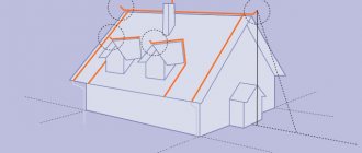
The main goal of both introductory and extraordinary tests, as well as scheduled inspections of lightning protection, is to establish compliance of the system parameters with design and technical documentation and current standards. The individual design features of the protective system of a particular facility influence the final content and scope of the tests performed. However, for all objects the following mandatory verification stages can be distinguished:
- Checking the compliance of protection zones and selected design and technical solutions with the requirements of current regulations.
- Comparison of design and operational documentation data with actual system performance.
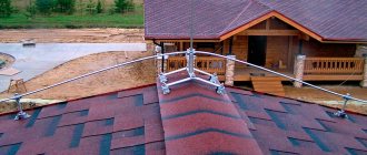
- Visual inspection of external devices and lightning protection elements (lightning rods, down conductors, contact connections, etc.) to check for mechanical and corrosion damage and assess the quality of the installation.
- Checking welds and joints for integrity and mechanical strength using specified external influences (by tapping with a hammer).
- Measuring the transient resistance of bolted connections.
Frequency of inspections
The first test of the lightning rod system is carried out immediately after its installation, and subsequent checks are carried out according to the schedule, at intervals specified in the rules and regulations.
According to the instructions regulating the technical design of lightning rod systems, their testing (regardless of the category of the building) must be carried out at least once a year. In turn, the rules defining the requirements for the operation of electrical installations state that the lightning protection grounding components must be checked:
- visually (visible grounding components) – every six months;
- control with removal of soil in the area of installation of grounding elements - once every 12 years (the choice of location for inspection is carried out selectively).
Assessment of resistance parameters that have grounding contours for power lines is carried out once every 12 years (for lines with voltages of more than 1000 volts). The resistance of lines with voltages up to 1000 volts is checked at least once every 6 years.
Where to look for standards for grounding resistance?
The results of grounding resistance measurements are compared with a certain limit value. Based on this comparison, a conclusion is made about the operability of the lightning protection grounding. But the question arises - where to find the maximum permissible resistance value for a given building?
Back in the 80s, when the guideline document RD 34.21.122-87 “Instructions for the installation of lightning protection of buildings and structures” was created, the standardization of grounding resistance for a lightning protection system was recognized as an outdated approach; instead, standard designs of grounding conductors were introduced, for which the geometric dimensions were standardized elements. SO 153-34.21.122-2003 also does not have specific standards for grounding resistance. Standard designs of grounding electrodes are convenient for design, but how to check the performance of existing grounding electrodes? The question remains up in the air to this day.
However, there is a way out. Almost any modern building has electrical equipment. According to the PUE standards, the grounding of lightning protection and electrical equipment must be combined into a single circuit. Well-known lightning protection specialist, Doctor of Technical Sciences, Prof. E.M. Bazelyan recommends comparing the resistance of this circuit with the PUE standards for grounding resistance for electrical equipment. Moreover, as a rule, it is not possible to separate both types of grounding conductors when carrying out measurements. The relevant data is given in PUE-7, Ch. 1.7, the maximum permissible resistance values generally depend on the power supply system and the supply voltage of electrical installations. For greater reliability, you can measure resistance for the same ground loop using both the pulse method and alternating current. Modern measuring instruments for this application have a corresponding function.
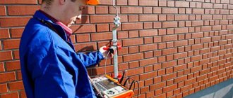
Test methods
Instrumental. Testing using tools allows you to determine the resistance level of lightning protection grounding conductors. The parameters of the transition resistance of lightning protection circuits are also assessed in those areas where their individual components are fixed.
Visual inspection . Produced during daylight hours, in sunny weather. During the inspection, the presence of damage (including corrosion) on the surface of lightning protection components is assessed. Example: for lightning rods, the basis for mandatory replacement is damage whose area exceeds a quarter of their total area.
Verification stages: main activities
Lightning protection testing includes:
- Visual inspection . The condition of the system components is checked (safety, absence of corrosion), including the lightning rod, current drainage elements, the integrity of their fastening to the masts, and the reliability of fixation;
- Troubleshooting . Identification of components that require repair or replacement due to loss of strength due to corrosion or mechanical damage. Welded joints are checked by tapping with a hammer;
- Test for reliability of electrical connections . Live parts of all devices and system components are checked, the insulation condition is assessed;
- Assessing the compliance of system devices with the purpose of the facility or building. The validity of installing lightning protection of this type at the site and its compliance with the design documentation is checked;
- Resistance measurements. The resistance to current flow is checked using a certified device: the grounding conductors of all free-standing lightning protection systems are tested. During tests, resistance indicators should not be more than 5 times higher than the indicators obtained upon acceptance of the system.
It is recommended to evaluate the grounding parameters of the system when the soil freezes the most severely, or in conditions of absence of precipitation. Both of these conditions provide the greatest soil resistance. Carrying out tests under other conditions requires the use of correction factors to obtain more accurate measurement results.
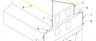
Scheme for measuring resistance using the four-wire method
Testing by the pulse method on a relatively small current makes it possible to create a compact measuring device with which you can travel to sites. Pulse current measurements are usually carried out using a four-wire circuit. This scheme is preferable because it avoids a significant influence of the parameters of the wires connecting the device with the measuring probes on the measurement results.
The current trend is to equip instruments for measuring ground resistance with a built-in GPS module. Such devices automatically record measurement results into memory along with the coordinates of the object being tested.
Measuring instruments
The installation quality of the lightning protection system is checked using special measuring equipment. This category includes both manually adjusted and automatically adjusted measuring equipment. In this area, priority is given to modern automatic meters, while manual devices are considered less reliable and outdated technology.
Among the self-tuning meters used for testing lightning protection systems, the most used is the MRU-101 device. It can be used to control resistivity, grounding resistance parameters, as well as characteristics such as spreading current. The device can store hundreds of measurement indicators in memory and selects a range that includes the desired settings.
The obvious advantages of this device include the indication of a potential error in the readings - in such a situation it gives a special signal. In addition, using the MRU-101, you can constantly monitor measurement conditions and noise levels: if an obvious error is detected, the measurement process will stop completely.
Operation of the device. The most common test method choice with the MRU-101 is the 3-pole circuit. In this case, three probes are driven into the ground in the area where the grounding components are located at a distance of up to 20 meters from each other. Then the working inputs of the device (E, H and S) are connected to the probes.
Another, more accurate method is to use a 4-pole circuit. Its difference from the above-described circuit is the connection of the electrode connected to the input marked “E” to the input wire marked “ES”.
Non-contact measurement technology. Measurements using MRU-101 can also be carried out non-contactly - for this purpose, special pliers are used, which are supplied with the device. Before use, the clamps are calibrated and then connected to the fifth input.
Measuring devices and optimal conditions for measurements
Resistance and other parameters of grounding devices are measured using high-precision instruments, while observing the frequency of lightning protection checks. Among them, the most commonly used devices are M-416 and MPI-511, used in combination to measure resistance and other indicators of protective equipment. Codes and regulations allow the use of other measuring devices with similar or similar parameters.
Among analogues, the MRU-101 meter has proven itself well, with the help of which resistance measurements in grounding devices are carried out, as well as soil resistivity. A large number of additional functions allow you to perform certain actions and analyze conditions that have a negative impact on the accuracy of the results. The device includes a current clamp that allows you to measure resistance without disconnecting the ground electrodes. In studies, three- or four-pole methods can be used. The device itself has increased resistance to external interference.
Obtaining the most accurate results depends largely on weather conditions. The best results from testing lightning protection devices are obtained during periods and seasons when the soil moisture near the circuit is the least. In the northern regions there are large zones with permafrost. Here experts recommend measuring resistance when the soil reaches its maximum freezing.
Building classification
In accordance with PTEEP, architectural objects are divided into categories I, II and III according to the level of lightning protection.
The first category includes objects and buildings whose specific operation is the accumulation of explosive and fire hazardous substances in various forms. In the event of a lightning discharge at such a facility, there is a high risk of injury to personnel and damage to nearby buildings and structures.
The second category includes those facilities that are equipped with external equipment that uses explosive and flammable substances in the form of liquid or gas. In addition, this category includes those objects in which hazardous substances can accumulate only when equipment breakdowns occur or technology violations occur.
The third category includes all other objects in which a discharge causes less damage or does not pose a high danger.
Requirements for an organization testing lightning protection
Only those organizations that:
- have a specialized laboratory with a registration certificate;
- use laboratory specialists with specialized education for testing;
- use measuring equipment.
Lightning protection testing is necessary for a number of reasons. Among them is the need to ensure the safety of personnel and the safety of the facilities themselves. In addition, you need to take into account that the lightning rod is constantly affected by precipitation, temperature changes, ultraviolet radiation and wind.
Documentation drawn up based on the results of inspections
After testing is completed, specialists from the inspection organization draw up reports and protocols. They include data:
- about resistance measurements when testing ground loops;
- on the results of a visual inspection of the lightning rod or its individual components;
- about the results of measuring contact resistance.
The specified documentation is drawn up in accordance with GOST R 50571.16-99. They reflect the results of all stages of testing the system, or contain the obtained characteristics of its individual components.
The protocols indicate the type of measuring devices, measurement conditions, note the violations and defects found, give a description of the object, and also indicate the names and other data of the persons who carried out the testing.
What requirements must the inspection protocol meet? Differences between an act and a protocol
Protocols. The test results document must include all data that is needed to justify a decision about the suitability or unsuitability of a lightning rod to protect a structure, building or other object under standard operating conditions. It must be supplemented with a lightning protection circuit diagram. Also attached to it are certificates of certification of laboratory specialists, certificates of timely verification of meters and other documents.
Acts. Unlike the protocol, this document is drawn up only by a commission, which includes an odd number of members. This document must be approved by the manager or deputy manager of the customer. In relation to lightning protection, two acts can be drawn up - acceptance and inspection. If the inspection report is drawn up de facto, it is drawn up as a protocol.
The acceptance certificate must be accompanied by a measurement protocol: as a rule, the acceptance certificate is a general document, and the main information is contained in the appendices.