At the stage of commissioning cable routes, electricians take some measures to increase the safety of the equipment. Such actions include grounding cable trays.
There are many types of trays, differing in the type of grounding. The most common type of trays is wire. They must be installed in accordance with the conditions set out in GOSTs and PUE (Electrical Installation Rules).
Reasons for the popularity of wire trays
First of all, these trays are more affordable. The advantages of these structures also include the low cost of their installation. Without touching on the material component, the advantage of this type of tray is also its high level of electromagnetic compatibility. Another definite plus is the provision of high-quality cable cooling. Other reasons for the relevance of wire trays include:
- no need to use additional expensive accessories;
- no dust on the surface of the trays;
- high level of load capacity.
What to consider when choosing trays?
Let's try to consider in more detail the criteria that determine the parameters of the trays:
- The dimensions of the trays directly depend on the number of cables and their diameter. The maximum dimensions of the cable bundle should be slightly less than the height of the tray walls. The total number of cable diameters must be less than the width of the tray.
- Cable heat sink. It all depends on the type of energy flowing through the cables. The main loss of power in them occurs due to heating. To do this, it is necessary to provide additional space in the trays. If the cable does not heat up, then you can choose trays with a high wall for laying in several layers. If it is subject to heating, then you need to choose a tray with low sides. Wire or perforated trays are selected when there are more stringent heat dissipation requirements.
- The ease of installation of the system greatly depends on the design features. Cheaper trays with straight ends require connecting pieces, making installation more complex and time-consuming. For high installation speed, more functional designs are needed, for example, our trays use a female-male connector.
- The strength of the tray is selected based on the total weight of the cables. For trays with higher walls, thick steel is used, and accordingly their load-bearing capacity is much higher. Ladder trays can carry the heaviest load. Non-perforated metal trays, in terms of load capacity, do not differ from perforated ones.
- The level of protection required is determined by the type of cable and is specified by its manufacturer. Wire trays have minimal protection, while non-perforated trays with lids have maximum protection.
- The minimum bending radius of cables is indicated by the manufacturer; when selecting a tray, the bending of the cable should be significantly greater than the bending radius of the accessories for the style. Due to the physical nature of the energy that passes through a fiber optic cable, the bending radius of the cable must be especially carefully considered.
- The degree of corrosion depends on the climatic conditions of the place where the route will be located. Galvanizing the tray with various materials is necessary to increase its durability. The level of anti-corrosion protection directly depends on the thickness of galvanization. Galvanized trays with a galvanizing thickness of up to 10 microns are good for indoor placement. Trays galvanized by hot-dip method and having a layer thickness of up to 60 microns should be used when placing the route externally. And stainless steel products are suitable in the chemical or food industries, when placing routes in tunnels.
Remember that the main task that metal trays perform is protection from external factors. In this regard, the correctly selected product and high-quality assembly will guarantee the best technical and economic result.
Grounding trays using PUE - All about electricity
In order to commission cable routes, it is necessary to take various measures to improve the safety of the equipment. One of these measures is the grounding of cable trays. This process must be given special attention in order to do everything correctly and in accordance with GOST standards. It should also be noted that cable trays come in many different types, so the connection method is different.
They can be wire, sheet, perforated and all-metal. We will talk about how to ground each of the design options below.
Metal communication
There are several types of cable channels, so the grounding of metal cable trays is carried out taking into account the design features, especially when installing wire trays. Installation must necessarily comply with the rules for working with electrical installations and be carried out in accordance with GOST.
The cable route can be considered a grounding conductor if special connecting devices are additionally installed - jumpers, or cable channels mounted in accordance with the instructions of GOST 10434-82. To simplify work with the grounding system, jumpers should be color coded. They are usually painted in a green-yellow color scheme.
When making jumpers yourself, it is important to remember that the ends of the trays must be processed. For this purpose, you can use the crimping method
Clamps are not used to secure to a support or connect parts of a cable tray. They must perform a purely protective function for conductors.
Some parts for cable routing have washers with a rough, scratchy surface. This part performs an important function - it improves the reliability of the electrical connection. Thanks to this, the possibility of loosening the nuts is practically reduced to zero.
Determining the point of connection of the wire to the highway
To determine the point of connection of the wire to the potential equalization system, you should be guided by the provisions of the “Instructions for lightning protection and construction of grounding networks.” According to the data specified in this instruction, the connected sections of trays, profiles, cable blocks and other electrical wiring elements must form a continuous electrical circuit. Moreover, they must be connected to the highway in at least two places - at the beginning and at the end. If the length of the electrical wiring structures does not exceed two meters, then it is possible to connect the wire in only one place.
To summarize, it should be said that for grounding cable trays made of wire, you should use PVZ-4 mm² wire. Grounding terminals must be installed along the entire route. In this case, the wires must be connected to the EMS.
2.3.124
Laying of control cables is allowed in bundles on trays and in multilayers in metal boxes, subject to the following conditions:
1. The outer diameter of the cable bundle must be no more than 100 mm.
2. The height of the layers in one box should not exceed 150 mm.
3. Only cables with the same type of sheaths should be laid in bundles and multilayers.
4. Fastening of cables in bundles, multilayered in boxes, cable bundles to trays should be done in such a way that deformation of the cable sheaths under the influence of its own weight and fastening devices is prevented.
5. For fire safety purposes, fire-barrier belts must be installed inside the boxes: in vertical sections - at a distance of no more than 20 m, as well as when passing through the ceiling; in horizontal sections - when passing through partitions.
6. In each direction of the cable route, a reserve capacity of at least 15% of the total capacity of the boxes should be provided.
Laying power cables in bundles and multi-layers is not allowed.
Use of Grounding Materials
Grounding cable channels and using metal boxes as a conductor is permissible if there is permission in the technical passport of the facility.
Operation of the structure is possible subject to the following conditions:
- each element of the cable support line has a good galvanic connection;
- the cable route has no interruptions;
- the quality and functionality of the design are checked in a timely manner by specialists;
- along the length of the structure, all elements are connected taking into account the requirements of regulatory documents;
- the required cross-sectional area of the trays is provided along the entire route line.
After the start of operation, it is important to carry out timely inspections of the grounding system and check it for serviceability. It is important that the inspection is carried out by a specialist - this will help increase the safety of the structure. To use a cable tray as a PE conductor, it is necessary to calculate the short circuit, and then select elements of grounding equipment.
It is also better to entrust this process to a specialist who has detailed information about the object and can adequately assess the design features. Next, the minimum separation of the PE conductor is determined according to the rules describing the grounding of trays according to the PUE.
To complete the calculations, you will have to compare the minimum indicator of the PE conductor with the cross-sectional areas of the main communication line along the entire route.
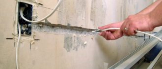
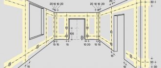
What are the advantages of hidden wiring
To begin with, pay attention to the following: hidden wiring in a frame house or apartment implies destruction of the cladding on the walls and ceiling, the floor surface may be damaged, so you should think about the need for its installation or partial replacement every time a major renovation of the room is carried out. It is much more convenient to carry out the process at new facilities
The main advantages of organizing hidden cable routing:
- All parts of the system are hidden under a facing layer of plaster or plasterboard sheets, so the appearance of the premises does not deteriorate.
- A high level of fire safety, provided that the walls are made of concrete or other material that does not support combustion. Even if ignited, the fire will not spread, since there will be no oxygen or flammable atmosphere in the walls.
- The cable hidden in this way is well protected from ultraviolet radiation and mechanical shock, which increases the service life of the entire system.
Hidden wiring does not spoil the appearance of the walls
The disadvantages of this method are primarily related to the complexity of installation, the need to destroy walls and the difficulties encountered in repairing and maintaining wiring. The cable and other elements are hidden under a layer of plaster, so if necessary you will have to remove it every time. All this cannot be said about electrical systems equipped in an open way.
However, hidden wiring is the most relevant, reliable, safe and correct solution for any permanent housing. In log houses, garages, bathhouses and similar buildings, you can use open electrical wiring.
Exposed retro wiring in a wooden house
Simple grounding scheme
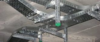
The design of the wire tray creates the effect of a “Faraday cage” - it prevents electrical waves from escaping: thus, not only the contents are protected, but also what is outside it.
Wire systems, like any other, must be connected to a potential equalization system (EPS). But since their connection points do not provide the necessary conductivity, it is necessary to take additional measures - installing an additional control system at the ground terminals.
They are mounted to the walls every 10-20 meters and a copper wire with a cross-section of 4 mm is passed through. At the connection points it must be bare, the insulation removed. The ends of the wire on both sides are connected to the potential equalization system: thus, there must be at least two terminals in the design.
An exception is for trays less than 2 meters long - here one terminal can be connected. Thus, a single continuous electrical network is obtained.
The “rule of two connections” was originally prescribed in the grounding rules for explosive objects, where wires are not used. But the opinion of experts is that additional security measures never hurt. Open conductive parts of structures and neutral protective conductors are connected to the additional control system.
The tray can also be used as a protective conductor if this is provided by the manufacturer in the design and technical documentation. Then the system must be installed in a place where it is completely insulated and protected from mechanical damage.
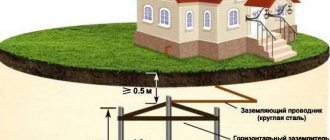
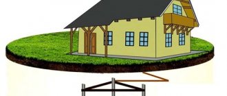
Ring ground electrode
A flat wire made of galvanized or stainless steel (30x3.5 mm, 40x4 mm), a round electric copper wire (8 mm), a round wire made of galvanized or stainless steel (10 mm) can be used as a grounding electrode. The ground electrode made from the above materials is laid in the form of a ring around the perimeter of the architectural structure at a distance from the foundation of at least one meter and to a depth of at least half a meter. When laying, at least 80% of the grounding conductor must be in the soil. All elements of the general electrical system of the building, as well as cable trays and wire boxes, are connected to one ring grounding conductor.
Deep ground electrode
The deep ground electrode is made of the same materials, but is located vertically in the ground, not along the perimeter of the building. Depending on the class of lightning protection and grounding of electrical boxes for laying wires or cables, the depth of location is determined. The ground electrode is placed at a distance of at least one meter from the foundation of the building to a depth of 2.5 to 9 meters. When installing lightning protection, the number of grounding conductors is determined by the number of down conductors from the lightning rod.
When installing a classic grounding system, several down conductors can be connected to one ground electrode. If there are several deep ground electrodes around the building, they must be additionally connected to each other.
Foundation ground electrode
As the name suggests, this type of ground electrode is located directly inside the concrete foundation of a building or structure, or, in other words, the reinforcement of reinforced concrete piles or a flat foundation is used as a ground electrode. This type of grounding must be provided at the design stage. For already constructed objects, the implementation of foundation grounding of metal cable ducts and trays is not possible or difficult to implement.
Installation instructions
Cable laying can be done either singly or in several layers. They can also be released by first collecting them in bundles and bags. When laying in rows, a distance of five millimeters between live parts is required, in other cases this distance increases four times (20 mm). For the multilayer version, the gap can be neglected. When laying cables in a bundle, it is unacceptable to have more than twelve wires. At the same time, the radius of the beam should be no more than 10 cm.
If you plan to lay the wires horizontally in the tray, you need to collect them in bundles, maintaining a distance of 4.5 meters between the bundles. By the way, in this case it is possible to neglect assembling cables into bundles if the sections are horizontal and straight. If laid vertically, a linking step of at least one meter is required.
When the structure is assembled and it has been fastened to the floors, using a specialized cord, the distance of the cable-bearing route is measured for subsequent cutting of live parts. After performing this operation, all cores are bundled and marked with tags. When the wires are laid in a tray and assembled into a circuit, you need to check it with a certified multimeter for the absence of breaks, and also measure the insulation resistance with a megohmmeter.
In order not to damage the cable, you need a temperature that corresponds to its characteristics during installation. If the indicator is -15 degrees Celsius or higher, laying can be carried out without heating. If the range ranges from -40 to -15 degrees, warming up is necessary, and at lower temperatures, work on the gasket is unacceptable.
The cable must be laid in the tray in such a way that a certain margin in length is provided. It is needed in order to compensate for changes in wire length due to temperature fluctuations. The entire cable with the appropriate margin must lie straight, since it is not allowed to run it with turns and rings.
If installation is carried out in an open space, for example on a wall on the street, the inevitable heating from solar exposure must also be taken into account. In this case, additional screens are installed to protect from sunlight.
When installing, you must strive to ensure that the trays are solid. That is, it is necessary to reduce to a minimum various cuts along overpasses in complex installation areas. The cable, regardless of the technical characteristics of the mounting supports, must be installed and secured at their extreme points, as well as at couplings, line turns and other connection points.
When installing a cable in a tray, it is necessary to take into account and compensate for possible deformations due to:
- electrical cable mass;
- mechanical stresses determined by temperature differences;
- actions of a magnetic nature that are possible during a short circuit.
If the cable line intersects with the pipeline, you need to maintain a distance between the tray and the pipes of at least 5 cm. When laying conductors and pipelines in parallel, the distance between communications must be at least 10 cm. In this case, the distance to the gas pipeline must be at least 25 cm. Read more these values are described in the PUE Chapter 2.1. clauses 2.1.56, 57, Chapter 2.3., clauses 2.3.86, 88, 95, 134 and others.
When laying wires, you need to fill no more than half the volume of the tray. This is necessary for:
- easy access for line repair and maintenance;
- Possibility of air cooling of wiring.
It is necessary to ensure that when laying the wires in the tray they have good metallic contact, since it is most often possible to lay grounding by connecting only to the extreme points of the cable connection.
Lines in a residential building must be installed at least two meters from the floor level. However, if the room is designed for work by personnel who have undergone appropriate training, the installation height does not matter.
The method of installing wiring along electrical trays and boxes is selected based on considerations of the absence of moisture and condensation inside them. If the installation is carried out in an open space, then for such installation you need boxes with a removable lid, which serves to provide quick and easy access to the cable. In enclosed spaces, it is permissible to use one-piece boxes for live parts of the circuit.
So we looked at how cable laying should be done in trays and boxes. We hope our installation instructions were useful to you and now you know how to properly route wires in a cable tray!
It will be useful to read:
- What types of cable channels are there?
- Laying cables through walls according to the PUE
- Methods for testing wires
Published: 04/22/2017 Updated: 04/03/2019
Removable tray covers
When installing a cable route, you must take into account that the tray covers are not part of this structure, so they should not be grounded. For the reason that the removable cover with grounding initially has an excellent level of protection against electric shock. The products provided by DSK are installed very simply and quickly.
For installation, you just need to choose the best method: by drilling holes in the wall, or using hangers. Each surface of this design has special contours and additional accessories. To fix the grounding wire, you can use an M5 bolt.
It is required to approach this work correctly and constructively, because thanks to this you can be confident in protection from electric shock in the event of a short circuit, which is immediately transmitted to the base body.
The importance of using removable lids
When arranging cable routes, it is important to remember that removable tray covers do not require grounding, like the rest of the structure. This became possible due to the high level of protection of these products from the negative effects of current.
High-quality removable covers for trays can be easily installed using hangers or mounted directly on the wall. On top of these parts there is a coating in the form of a grounding loop. The wire for grounding the trays is fixed quite simply using an M-5 class bolt. Ultimately, grounding metal trays prevents electric shocks from short circuits.
The use of removable covers for trays is also convenient because they can be quickly mounted and removed without additional equipment. Therefore, additional cables can be added to existing cable channels at any time.
In addition, this element allows you to quickly inspect the structure during a breakdown. As a rule, such covers are made from sheet metal and have different widths, which makes it easier to select the necessary parts and install them on the appropriate tray.
Conditions of use
The use of metal trays and boxes as PE-type conductors is only possible if there is permission in the technical data sheet of the design. This requirement is specified in Chapter 1.7 of the PUE. Operation is possible if the following conditions are met:
- there are no interruptions along the entire cable route;
- along the entire line, the required cross-sectional area of the trays and their connections along the entire length is ensured;
- line elements have high-quality galvanic connections;
- specialists promptly check the grounding of the perforated tray and the quality of fixation of connections.
To use a cable tray as a PE conductor, a number of requirements must be met. First, the short circuit current is calculated. Having correctly completed all the calculations, it becomes possible to optimally select elements of grounding equipment. Accurate calculations can be carried out by a specialist who has information about the parameters of the cable route.
Then the minimum cross-section of the PE type conductor is calculated. Here you should also use the recommendations of the rules for constructing electrical installations given in the PUE. Next, you need to compare the minimum cross-sectional area of a PE type conductor with the cross-sectional area of all elements that are present in the cable-supporting complex. This should be done along the entire route.
Peculiarities
On the territory of Russia there are specialized rules and standards. According to them, elements that can be quickly installed and removed do not require additional grounding. However, if there are special requirements, a special cover can be installed on the grounding tray. In this case, it is possible to install additional jumpers and grounding conductors that have sufficient galvanic connection. For example, the company DKS produces such products.
All conductive cable lines should be connected to a potential equalization system. In the case of ladder and sheet trays, things are a little better. The peculiarity is that wire trays cannot provide sufficient conductivity. As a result, it is important to provide a number of additional measures for connecting to the potential equalization system.
For example, the DKS company recommends creating connections every twenty meters. However, experts recommend doing this every ten meters. Such grounding is usually used if the structure is operated under more severe conditions.
To fully connect wire trays, it is recommended to use special grounding terminals. They can be found at any local market. The installation technology is quite simple. All you have to do is attach the terminal to the wall of the tray, and then pass the wire through it. At the point where the wire comes into contact with the terminal, you should remove the insulation. As a result, the grounding of metal trays becomes more efficient. The conductor can be a PVZ wire, which has a yellow-green insulation color.
Installation instructions
Cable laying can be done either singly or in several layers. They can also be released by first collecting them in bundles and bags. When laying in rows, a distance of five millimeters between live parts is required, in other cases this distance increases four times (20 mm). For the multilayer version, the gap can be neglected. When laying cables in a bundle, it is unacceptable to have more than twelve wires. At the same time, the radius of the beam should be no more than 10 cm.
If you plan to lay the wires horizontally in the tray, you need to collect them in bundles, maintaining a distance of 4.5 meters between the bundles. By the way, in this case it is possible to neglect assembling cables into bundles if the sections are horizontal and straight. If laid vertically, a linking step of at least one meter is required.
When the structure is assembled and it has been fastened to the floors, using a specialized cord, the distance of the cable-bearing route is measured for subsequent cutting of live parts. After performing this operation, all cores are bundled and marked with tags. When the wires are laid in a tray and assembled into a circuit, you need to check it using a certified multimeter for the absence of interruptions, and also measure the resistance of the insulating material.
For proper installation work, the appropriate temperature is necessary. If the indicator is -15 degrees Celsius or higher, laying can be carried out without heating. If the range ranges from -40 to -15 degrees, warming up is necessary, and at lower temperatures, work on the gasket is unacceptable.
The cable must be laid in the tray in such a way that a certain margin in length is provided. It is needed to compensate for changes in wire length due to temperature fluctuations, as well as soil deformations. The entire cable with the appropriate margin must lie straight, since it is not allowed to run it with turns and rings.
If installation is carried out in an open outdoor space, for example on a wall on the street, the inevitable heating from solar exposure must also be taken into account. In this case, additional screens are installed to protect from sunlight.
When installing, you must strive to ensure that the trays are solid. That is, it is necessary to reduce to a minimum various cuts along overpasses in complex installation areas. The cable, regardless of the technical characteristics of the mounting supports, must be installed and secured at their extreme points, as well as at couplings, line turns and other connection points.
When installing a cable in a tray, it is necessary to take into account and compensate for possible deformations due to:
- electrical cable mass;
- mechanical stresses determined by temperature differences;
- actions of a magnetic nature that are possible during a short circuit.
If the cable line intersects with the pipeline, you must maintain a distance between the tray and the pipes of at least 5 cm. When laying conductors and pipelines in parallel, the distance between communications must be at least 10 cm. In this case, the distance to the gas pipeline must be at least 25 cm.
When laying wires, you need to fill no more than half the volume of the tray. This is necessary for:
- easy access for line repair and maintenance;
- Possibility of air cooling of wiring.
It is necessary to ensure that when laying the wires in the tray they have good metallic contact, since it is most often possible to lay grounding by connecting only to the extreme points of the cable connection.
Lines in a residential building must be installed at least two meters from the floor level. However, if the room is designed for work by personnel who have undergone appropriate training, the installation height does not matter.
The method of installing wiring along electrical trays and boxes is selected based on considerations of the absence of moisture and condensation inside them. If the installation is carried out in an open space, then for such installation you need boxes with a removable lid, which serves to provide quick and easy access to the cable. In enclosed spaces, it is permissible to use one-piece boxes for live parts of the circuit.
So we looked at how cable laying should be done in trays and boxes. We hope our installation instructions were useful to you and now you know how to properly route wires in a cable tray!
It will be useful to read:
- What types of cable channels are there?
- Laying cables through walls according to the PUE
- Methods for testing wires
Wire trays
Advantages of wire trays
If we compare this version with other products, wire trays have quite a lot of positive features, here are some of them:
- installation is not too expensive;
- the products themselves are much cheaper than sheet products, as well as ladder types;
- wire cooling is much better than in designs with closed boxes;
- in order to ground the tray, you can use a fairly simple circuit;
- Very little dust accumulates inside, several times less than in galvanized or metal structures;
- in terms of load indicators, cable trays made of wire are not inferior to others, for example, sheet trays;
- There is no need to buy expensive additional accessories to use it.
It will take very little effort to ground the cable tray, because it initially has excellent electromagnetic compatibility. Products made from polyvinyl chloride are not able to provide high-quality interference suppression. Because of this phenomenon, metal cable trays produced by the DKS company began to be widely used by cellular operators.
According to the PUE, it is mandatory to ground all trays. The conductive supporting structure for the wires requires complete, comprehensive protection. And the work itself is carried out in full compliance with the standards that are in SNiP. For example, DKS brand trays are grounded at least at two points - at the beginning and the end.
Wire channels for laying cables are conductive and therefore need to be connected to a potential equalization system. Unlike the connections found in tape and sheet channels, wire trays have less contact and therefore less conductivity. For this reason, a special terminal is used, which ensures the required resistance value between the cable system and the ground bus.
Grounding inside a private house
Grounding cable laying diagram
According to the PUE, when grounding cable armor in domestic conditions, the following rules must be observed:
- armored cable 0.4 kV is allowed to be laid in metal structures that are reliably grounded and accessible for repair and maintenance;
- laying on concrete floors and wooden flooring is done with a gap of at least 5 cm, for this purpose metal boxes and special stands are used;
- Entry into the house can be done both through the floors and through a specially designated wall area.
To prevent damage to the entrance to the building in places where it is routed through walls or the foundation, the cable is laid in a pipe made of metal or plastic.
The diameter of the pipe section is chosen to be 2 times larger than the cross-section of the cable product itself.
When entering the line into the house, the armor is grounded in the distribution board, as well as on the side of the outlet support. According to the PUE, no other connections are allowed to be made on this section of the route. At the input, the cable is divided into several cores connected to switching devices; in this case, its armor is necessarily connected to a grounded point of the shield body - directly to the ground.
Grounding of cable trays: elements, requirements and application features
At the stage of commissioning cable routes, electricians take some measures to increase the safety of the equipment. Such actions include grounding cable trays.
There are many types of trays, differing in the type of grounding. The most common type of trays is wire. They must be installed in accordance with the conditions set out in GOSTs and PUE (Electrical Installation Rules).
Some inexperienced users feel that connecting trays with screws ensures cable continuity. However, reliable metal communication, which is judged by voltage conductivity, is not achieved in all electrical installations. The route refers to grounding conductors only if there are additional jumpers or in the case of connecting trays according to certain standards. The connection requirements are set out in GOST 10434-82.
To simplify orientation in the grounding system, the jumpers should correspond to a certain color scheme. Most often we are talking about a combination of green and yellow colors. The cross-section limits are set from 4 to 6 square millimeters.
When organizing grounding using self-made jumpers, one should not forget about an important rule: the ends must be processed. Processing means crimping. The screws for fixing the protective conductors cannot be used to solve other problems, for example, for joining the tray end or mounting on a support.
In some product modifications, screw hardware for trays are equipped with washers or nuts. These elements have a “scratching” surface. Thanks to this feature, more reliable electrical contact is ensured, since the risk of loosening fasteners is significantly reduced. Small copper plates are also used (they are also called busbars).
Requirements for conductors
When installing grounding, as well as protective grounding, steel cable sheaths of any class or armor are connected to the charger through copper conductors of a standardized cross-section. This requirement also applies to coupling or end coupling housings. On lines designed to transmit high-voltage power (6 kV and above) and having an aluminum sheath, coupling grounding is performed with separate conductors.
For this purpose, it is prohibited to use copper conductors with a conductivity greater than the corresponding indicator for cable sheaths.
The general requirements of current standards provide for the use of bare copper conductors with a cross-section of at least 6 mm square. The same parameters for control cables are specifically stipulated in the PUE (see clauses 1.7.76-1.7.78).
If the support of the air supply to the electrical installation is equipped with end couplings containing arresters, their housings are connected directly to the protective device charger. The use of cable sheaths alone in this capacity is not allowed in this situation. Special overpasses and galleries used to accommodate explosive cables must be equipped with protection against lightning discharges and lightning.
When moving from an underground laying line to a section of its overhead wiring and if the reinforced concrete support does not have its own charger, the couplings are allowed to be grounded to the cable armor. This approach is permissible only if the repair or extension coupling at the other end is connected to the station grounding circuit, or if the resistance value of the sheath of the grounded cable is sufficiently small.
Grounding trays to each other PUE
Before putting cable routes into operation, specialists take a number of additional measures to increase the safety of the equipment. One such measure is grounding cable trays. Since there are different types of trays, differences can be found in the grounding process. In particular, this applies to wire types.
In any case, the installation must comply with the regulatory requirements of GOST standards and electrical installation rules.
Packaging and transportation
Unprotected areas of cable ducts and trays must be preserved before transportation.
Straight sections may be partially packed. The ends must be closed with special plugs.
Elements of cable support systems are packaged in containers, wooden or other types, provided that the products are protected from mechanical damage.
When packaging, the weight of one piece of cargo should not exceed 500 kg. Each piece of cargo is equipped with a packing list with transport markings.
Cable boxes and trays can be transported by all types of transport, subject to compliance with the rules for the carriage of goods that apply to this type of transport.
The standard storage period for electrical boxes, trays and system components before commissioning is at least three years.
Lightning protection
The danger of lightning currents largely depends on the area of direct lightning strike. When lightning strikes directly into a building (for example, into part of a line when laying an electrical cable externally or into the roof), lightning protection and grounding systems must divert lightning energy to the ground potential. The calculated threat value is 200 kA.
When lightning strikes a grounded building, due to the impedance of the grounding device, the potential of the entire system can increase significantly, which leads to the separation of lightning currents through the grounding system itself and through networks of information wires and power cables to neighboring structures that have their own grounding system (neighboring buildings, transformers, etc.).
When lightning strikes a low-voltage overhead line or data line, the threat value is up to 100 kA. In this case, the discharge can trigger the occurrence of partial lightning currents in nearby buildings. Lightning striking electrical wires poses a particular danger to electrical installations located at the end of low-voltage overhead lines.
In the case of a close but indirect lightning strike, the threat value is only a few kA, but it produces high magnetic fields that lead to voltage surges in conductor systems. Due to inductive or galvanic coupling, such damage can occur within a radius of up to two kilometers from the point of lightning strike.
Is it necessary to ground cable trunking covers?
| Page 1 of 2 | 1 | 2 | > |
Parts to be grounded or grounded include:
housings of electrical machines, transformers, apparatus, lamps, etc. drives of electrical devices, secondary windings of instrument transformers, frames of distribution boards, control panels, panels and cabinets, as well as removable or opening parts, if the latter are equipped with electrical equipment with a voltage higher than 42 V AC current or more than 110 V DC; metal structures of switchgears, metal cable structures, metal cable couplings, metal sheaths and armor of control and power cables, metal sheaths of wires, metal hoses and electrical wiring pipes, casings and support structures of busbars, trays, boxes, strings, cables and steel strips, on which cables and wires are secured (except for strings, cables and strips along which cables with a grounded or neutralized metal sheath or armor are laid), as well as other metal structures on which electrical equipment is installed; metal shells and armor of control and power cables and wires with voltages up to 42 V AC and up to 110 V DC, laid on common metal structures, including in common pipes, boxes, trays, etc. Together with cables and wires, metal shells and armor of which are subject to grounding or neutralization; metal cases of mobile and portable electrical receivers; electrical equipment located on moving parts of machines, machines and mechanisms.
I suggest that you consider the tray covers as underlined and do not ground them.
| Geniy_Dzydo |
| View profile |
| Find more posts by Geniy_Dzydo |
| Geniy_Dzydo |
| View profile |
| Find more posts by Geniy_Dzydo |
Thanks for the answer! In principle, I completely agree with you. But perhaps someone will prove the opposite.
The topic is relevant. I look forward to your thoughts on this matter.
Where is this written?
| Geniy_Dzydo |
| View profile |
| Find more posts by Geniy_Dzydo |
Of course! PUE clause 1.7.82 subclause 4!
There is also a circular from Roselectromontazh on additional equalization of potentials in bathrooms, so even if the pipes are plastic, you need to insert a metal insert and attach a DSUP conductor to it - there is probably no such thing anywhere in Russia, but according to the standards https://www.news.elteh .ru/arh/2009/60/11.php
| Geniy_Dzydo |
| View profile |
| Find more posts by Geniy_Dzydo |
| 1.7.82. It is not allowed to use neutral working conductors going to portable single-phase and direct current electrical receivers as neutral protective conductors. To ground such electrical receivers, a separate third conductor must be used, connected in the plug-in connector of the branch box, in the panel, shield, assembly, etc. to the zero working or zero protective conductor (see also 6.1.20). |
| Geniy_Dzydo |
| View profile |
| Find more posts by Geniy_Dzydo |
Unfortunately, there is no such thing in the sixth edition, thanks for the link
so for general development, can you explain? Let’s say I have a 2-story building 60x30 m, the building has a water supply (long for the entire building), it is partly made of polyethylene and partly of metal. Does this water supply system need to be grounded in several places? Or is it enough to ground in one place? If in several places, then at what distance should it be grounded?
| Geniy_Dzydo |
| View profile |
| Find more posts by Geniy_Dzydo |
| Geniy_Dzydo |
| View profile |
| Find more posts by Geniy_Dzydo |
from the same series of metal tiles, there are some kind of scratching fasteners, so if it is assembled incorrectly, then some kind of charge can accumulate there (from lightning, as it were) and shudder! but this is an incorrect installation - if it was not assembled according to the documentation. And in your case: there are probably columns with half-timbers, purlins, etc. lying on them. the panels are attached to them, I don’t see a serial connection in this, rather a parallel connection with a bad contact, and then this bad contact is probably not so bad, but most likely there is a nut or washer with a scratching notch, so there should be contact. And how many grounding conductors did you get, and you brought them all to the GZSh. If you have any photos, could you post them! I found a thread here: https://forum.dwg.ru/showthread.php?t=43920
did you ground the sandwich panel on both sides?
Lightning protection systems
The most popular system for protecting buildings, structures and systems for laying electrical wires and cables from lightning is the so-called external system, consisting of an air terminal (pin, mesh or cable), a down conductor and a grounding system.
The lightning rod must be mounted in such a way as to reliably protect the corners of towering structures. The down conductor is responsible for the safe drainage of lightning current to the ground electrode. The number of down conductors is determined by the architecture of the building, but the minimum number of conductors, regardless of the dimensions of the building, is taken to be two. It should be taken into account that the down conductor must have a minimum length, and loops are not allowed. The task of the ground electrode is the safe distribution of currents in the ground.
Do trays with low-current cables need to be grounded?
- 17.04.2019
Do trays with low-current cables need to be grounded?
Grounding is an important measure to ensure the safety of the cable support system. Low-current systems have today become an integral part of administrative buildings, enterprises, and offices. Electrical networks with low-current cables include any cables laid in cable trays that carry low-voltage current (up to 100 Volts). Installation of low-current systems must be carried out in accordance with the rules for the design of electrical installations (PUE), regulations and standards, as well as using modern equipment.
Metal cable trays, regardless of what cables and wires are laid in them, must have grounding, since it is properly arranged grounding that helps provide protection from electric current or fire of the cable route.
Installation of a low-current network must be trusted only to qualified specialists, since the quality of signal transmission, communications, reliability and durability of the network as a whole, as well as the safety of equipment during operation depend on this. Grounding of low-current networks is carried out using a special grounding bus, which consists of insulated copper conductors. These conductors are used to connect the metal distribution box to the ground line. Grounding is carried out in at least two places on different sides of the network line, as well as additionally at the end of each branch.
LLC "PO Premium-Electro" produces cable trays and components for them of various types (including for low-current systems) coated with hot zinc or powder painting. You can see detailed information on the galvanized cable trays page, or check all the necessary information with the company’s managers by calling the numbers listed on the website.
How to ground cable trays
Before putting cable routes into operation, specialists take a number of additional measures to increase the safety of the equipment. One such measure is grounding cable trays. Since there are different types of trays, differences can be found in the grounding process. In particular, this applies to wire types. In any case, the installation must comply with the regulatory requirements of GOST standards and electrical installation rules.
Metal communication
Initially, the user may think that screwing the trays together using special screws allows for continuity of the cable structure. However, good metal bonding, expressed in a certain voltage conductivity, is not always ensured in electrical installations. Therefore, the route can be considered a grounding conductor only if additional jumpers are used or the trays are connected in accordance with a number of requirements of GOST 10434-82.
To make it easier to navigate the grounding system, jumpers are always color coded. As a rule, it is a combination of yellow and green. The cross section varies between 4...6 mm square.
When creating grounding of trays using jumpers made by yourself, you must always remember that you cannot leave the ends unprocessed. In practice they do pressure testing. Screws for clamping protective conductors should not be used for additional purposes, such as connecting the end of a tray or fixing to a support.
In some product models, screw hardware for trays may have washers or nuts with a so-called “scratch” surface. This technological solution was adopted by manufacturers to improve the reliability of electrical contact. Thus, the likelihood of loosening the nuts is reduced to zero. Alternatively, you can find small plates of copper called shreds.
Advantages of using wire products
Compared to a number of other products, wire cable trays have a number of positive features, namely:
- the cable variety is an order of magnitude cheaper than ladder and sheet type products;
- installation does not require serious financial costs;
- the cost of production makes it possible to extract additional financial benefits;
- Compared to closed boxes, the cables are cooled much better here;
- grounding is carried out according to a relatively simple scheme;
- less dust accumulates inside;
- no need to purchase expensive accessories for operation;
- from the point of view of load indicators, a cable tray is in no way inferior to a sheet tray.
Grounding a wire tray requires less effort, since the product initially has good electromagnetic compatibility. The reason for this is the design, which creates a “Faraday grid” effect. Products made of polyvinyl chloride cannot provide high-quality suppression of electromagnetic interference. The result of this is the widespread use of metal cable routes produced by LineTok by cellular operators.
From the point of view of regulatory documentation, grounding of trays via PUE is mandatory. The conductive cable-supporting structure requires comprehensive protection, and the procedure itself is carried out in accordance with the profile requirements.
Removable covers
When arranging a cable-supporting route, it is necessary to remember that removable tray covers are not part of the structure that requires mandatory protective grounding. The reason is that the grounded tray cover initially has a good level of protection against electric shock.
Products from LineTok are initially characterized by ease of installation. To install it, you just need to choose the best way to do it - using hangers, or by drilling holes in the wall. There is a grounding loop on any surface of the structure, including the cover and additional accessories. To fix the grounding cable, it is enough to use an M5 bolt.
With this design solution, grounding the trays provides complete guarantee of protection against electric shock in the event of a short circuit that is transmitted to the body of the supporting base.
Conditions of use
The use of metal trays and boxes as PE-type conductors is only possible if there is permission in the technical data sheet of the design. This requirement is specified in Chapter 1.7 of the PUE. Operation is possible if the following conditions are met:
- there are no interruptions along the entire cable route;
- along the entire line, the required cross-sectional area of the trays and their connections along the entire length is ensured;
- line elements have high-quality galvanic connections;
- specialists promptly check the grounding of the perforated tray and the quality of fixation of connections.
To use a cable tray as a PE conductor, a number of requirements must be met. First, the short circuit current is calculated. Having correctly completed all the calculations, it becomes possible to optimally select elements of grounding equipment. Accurate calculations can be carried out by a specialist who has information about the parameters of the cable route.
Then the minimum cross-section of the PE type conductor is calculated. Here you should also use the recommendations of the rules for constructing electrical installations given in the PUE.
Peculiarities
On the territory of Russia there are specialized rules and standards. According to them, elements that can be quickly installed and removed do not require additional grounding. However, if there are special requirements, a special cover can be installed on the grounding tray. In this case, it is possible to install additional jumpers and grounding conductors that have sufficient galvanic connection. For example, the LineTok company produces such products.
All conductive cable lines should be connected to a potential equalization system. In the case of ladder and sheet trays, things are a little better. The peculiarity is that wire trays cannot provide sufficient conductivity. As a result, it is important to provide a number of additional measures for connecting to the potential equalization system.
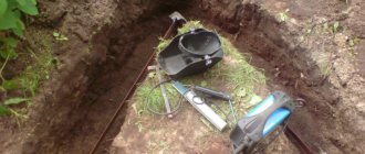
Grounding armored cables indoors
Armored cable 0.4 kV can be laid over any metal structures if they are grounded and also accessible for maintenance. Laying on wet concrete and wooden surfaces is prohibited. In this case, you need to provide a gap of at least 5 cm between the line and the surface; for this you can use various brackets or lay the line in metal pipes and gutters.
An armored cable can be inserted into a building through the foundation and walls. In order to eliminate the possibility of damage, a metal or plastic pipe with a diameter 2 times larger than its outer diameter must be laid at the cable entry, or at the point of transition through a wall or foundation.
The next step is that the armor needs to be grounded in the shield and at the side of the support from which it comes. Also, as described above, there should be no connections in this area (support-shield). At the input to the shield, the cable is divided into cores, which are connected to switching devices (switch or automatic circuit breakers), and its armor is connected to the shield body. That, in turn, must be grounded.
In cable structures (trays, galleries, overpasses, under floors), it is permissible to ground the armor by ensuring contact with metal boxes, channels or other grounded structures.
To organize an electrical network in a private house, it is connected to the power line using an overhead or underground connection. In the case of laying cables underground, VbBShv is often used; its armor, as in the cases described above, must be grounded on both sides.
The screen of control cables or optical cables must be grounded on at least one side. This is done to reduce or completely eliminate the influence of electromagnetic fields on the information line.
However, this task is better handled by double-sided grounding. The screen is connected to the main shield using a flexible conductor with a cross-section of at least 4 square meters. mm.
Technical support "RIPS".
You can ask any questions about RIPS products by email [email protected]
- Range
- Application of specific solutions
- Technical application standards
- Installation and dismantling
- Usage
- Repair
- Replacement
- Analogs
- Upgrade
- Much more.
Most often, requests concern grounding . Our comment:
Additional features
If we talk about the process of grounding cable trays itself, some companies recommend doing it at intervals of twenty meters. However, according to experts, grounding should be done every ten meters. Such grounding is used when the structure is operated in unfavorable conditions.
For correct and reliable connection to the cable holder, it is recommended to use special and sometimes reinforced terminals. They are sold in almost all markets or construction hypermarkets. Installation is very simple. First, you need to attach the terminal to the side wall of the tray, then pass the cable through its hole. At the point where the wire contacts the hole, the insulation should be stripped from the terminal.
Now you know how cable trays are grounded and what requirements need to be taken into account when organizing this type of protection. We hope the information was useful and understandable for you!