December 8, 2020
Dreaming of a carefree life in a cozy private home, many completely forget about banal security measures. This applies not only to security systems, but also to more important structures such as lightning rods and grounding.
The main problem is that these things seem ordinary, or, on the contrary, completely unnecessary. Most new owners of private homes pay absolutely no attention to this issue, faced with regular breakdowns of household appliances and electronics.
Organizing proper grounding in the electrical network of a private home is not a need, it is a necessity. This system allows you to secure the process of using household electrical appliances, and at the same time protect you from colossal expenses in the event of their breakdown due to short circuits and power surges.
Although the contours themselves are quite understandable structures, there are many nuances, including design requirements for each type of residential building. That is why we will tell you not only how to correctly make a grounding loop, but also how to perform calculations, prepare financially for the procedure, and select the necessary tool.
Features and principles of grounding
The purpose and objectives of the ground loop are quite capable of characterizing the structure itself.
Grounding is a connection of all elements and “participants” of the electrical network with a grounding loop, which allows, in the event of leakage currents, to safely discharge them into the ground.
Damage to insulation, short circuits, and almost any other troubles that may arise during the operation of devices can be neutralized due to a properly installed ground loop.
In simple words, if the electrical wiring is damaged, the electric current will not harm you or your loved ones.
The main danger of short circuits is that they not only disable electrical appliances, all the accumulated potential will be transferred to the conductor at the first opportunity, which, in the event of touching bare wires, is a person. Grounding is designed to take on the task of safely draining electricity into the ground in the event of a breakdown in the electrical network.
Calculation of the grounding device
In the modern world, we cannot imagine our life without the use of electricity. It is all around us and it is precisely this that has allowed humanity to move to a completely new level of development. It is impossible to overestimate its importance, however, for all its positive qualities, behind its harmlessness and simplicity, hides colossal energy that poses a mortal danger.
In order to secure premises where people are constantly present, a special device was created - a grounding switch. This is a set of conductors that are designed to drain electrical energy from devices to the ground, thereby eliminating electric shock to a person. It consists of grounding rods (horizontal and vertical rods) and grounding conductors.
Is grounding necessary at all in private houses?
As mentioned above, a ground loop is an excellent safety measure for homeowners. But is grounding really necessary in private homes? Now we will explain everything both from a safety point of view and based on the requirements of legislative acts.
Grounding is not an ideal means of protection against electric shock, since not all designs are capable of discharging large amounts of energy almost instantly. Despite this, even a decrease in the accumulated potential can significantly reduce the strength of electric shock. In critical situations, this allows you to avoid a lot of troubles, including death.
In addition to practical necessity, it is worth taking into account the requirements of legislative norms, which are quite understandable and transparent.
According to GOST, SNiP and PUE, all residential premises are required to be equipped with similar protection systems. The lower threshold in the requirements for installation of such circuits is an alternating current power supply of 100 Volts and more than 40 W.
Thus, 90% of all household networks in our country should be equipped with similar units to ensure the protection of homeowners from injuries.
Also, a grounding loop is one of the effective fire safety measures. Small fires, or large fires, bring much more losses than the cost of installing grounding, so you should definitely equip your own house with a similar design.
An interesting fact is that the lack of grounding in a private home can negatively affect the quality of mobile communications. An ungrounded electrical network creates a lot of interference for almost any electronics, so many people ask this question only after encountering interference with the equipment.
It is also worth considering that although the grounding system and lightning rod have similar principles of operation, the contours of these systems should in no case be ringed. In the case of a lightning strike, such a move can lead to even more negative consequences. A powerful electrical discharge will simply destroy all electronics, and as a result can create a fire inside or outside the house.
How to do proper grounding at your dacha: the dangers of lack of grounding for your home
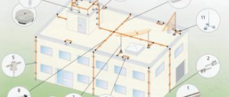
The construction of a private house or country house always involves a large amount of electrical work. In this range of tasks, along with supplying power to the house, installing distribution and protective equipment, laying internal lines, a well-planned and executed grounding system is no less important. Unfortunately, when carrying out self-construction, inexperienced owners quite often forget about this point or even deliberately ignore it, trying to achieve some kind of false savings in money and labor costs.
How to make grounding at the dacha
Meanwhile, the grounding system is of extreme importance - it can prevent many troubles that can lead to very sad or even tragic consequences. According to existing rules, electrical network specialists will not connect a house to a power line if this system is not in the house or if it does not meet the necessary requirements. And the owner, one way or another, will have to decide the question of how to make grounding at the dacha.
Expert opinion: Afanasyev E.V.
Chief editor of the Stroyday.ru project. Engineer.
In modern urban buildings, a grounding loop is necessarily provided at the design stage of the building and its internal communications. The owner of a private home will have to decide this issue himself - invite specialists or try to do everything himself. There is no need to be afraid - all this is a completely doable task.
Why is a ground loop needed?
In order to understand the importance of grounding, basic concepts from a school physics course are enough.
The vast majority of private homes are powered by a single-phase 220 volt AC network. The electrical circuit necessary for the operation of all devices or installations is provided by the presence of two conductors - actually, a phase and a neutral wire.
Typical wiring diagrams for a single-phase electrical network
The design of all electrical appliances, tools, household and other appliances includes insulation elements and protective devices that should prevent voltage from entering conductive housings or casings. However, the possibility of such a phenomenon can never be excluded - the insulation can be broken by a discharge, burn out from unreliable, sparking contacts in wire connections, circuit elements can fail, etc. In this case, phase voltage may reach the body of the device, touching which becomes extremely dangerous for humans.
Situations are especially dangerous if there are metal objects near such a faulty device that have so-called natural grounding - heating risers, water or gas pipes, open reinforcement elements of building structures, etc. At the slightest touch to them, the circuit can close, and a deadly current will pass through the human body towards a lower potential. Similar situations are no less dangerous if a person is standing barefoot or in wet shoes on a wet floor or ground - there are also all the prerequisites for shorting the alternating current circuit from the device body.
One of the expressed properties of electric current is that it will definitely choose a conductor with minimal resistance. This means that it is necessary to create in advance a line with minimal resistance and zero potential, along which, in the event of a breakdown on the housing, the voltage will be safely discharged.
The resistance of the human body is an unstable value, depending on individual characteristics and even on the temporary state of the person. In electrical engineering practice, this value is usually taken as 1000 Ohm (1 kOhm). Therefore, the resistance of the ground loop should be many times lower. There is a complex calculation system, but they usually operate with values of 30 Ohms for the household electrical network of a private house and 10 Ohms if the grounding is also used as lightning protection.
The RCD will work correctly only if there is a ground loop
It may be objected that all problems can be completely solved by installing special protective devices (RCDs). But for the correct operation of the RCD, grounding is also necessary. If even the slightest current leak occurs, the circuit will close almost instantly and the device will operate, turning off the dangerous section of the home electrical network.
Some owners are prejudiced that for grounding it is enough to use water supply or heating pipes. This is extremely dangerous and completely unreliable. Firstly, it is impossible to guarantee effective stress removal - the pipes may be heavily oxidized and may not have good enough contact with the ground, and in addition, they often have plastic areas. Electric shock cannot be ruled out when touching them in the event of a breakdown of the power supply to the housing, and neighbors may also be exposed to such a danger.
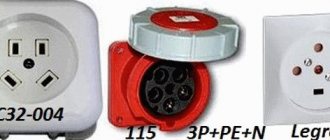
Plug and socket with grounding contact
Most modern electrical appliances are immediately equipped with a power cable with a three-pin plug. Appropriate sockets must also be installed when installing wiring in the house. (Some older model electrical appliances have a contact terminal on the body for a ground connection instead.)
Color marking of single-phase cable wires
There is a strictly defined color “pinout” of the wires: the blue wire is definitely “zero”, the phase can have different colors, from white to black, and the ground wire is always yellow-green.
And so, knowing this, some “wise” owners, wanting to save on updating the wiring and organizing full grounding, simply make jumpers in the sockets between the neutral contact and the grounding. However, this does not solve the problem, but rather aggravates it. Under certain conditions, for example, in the event of a burnout or poor contact of the working zero in some part of the circuit, or in the event of an accidental phase change, a phase potential will appear on the device body, and this can happen in the most unexpected place in the house. The danger of electric shock increases many times in such a situation.
Grounding is a reliable protection against many troubles
The conclusion from all that has been said is that grounding is a mandatory structural element of the home electrical network. It immediately performs the following functions:
- Effectively removes voltage leakage from conductive parts, touching which can cause electric shock.
- Equalizing the potential of all objects in the house, for example, grounded appliances and heating pipes, water supply, gas supply.
- Ensuring the correct operation of all installed safety systems and devices - fuses, circuit breakers or RCDs.
- Grounding is also important in preventing the accumulation of static charge on the housings of household appliances.
- It is of particular importance for modern electronics, especially computer technology. For example, the operation of switching power supplies for computers is very often accompanied by the induction of voltage onto the housing of the system units. Any discharge can lead to failure of electronic components, malfunctions, and loss of information.
Now that the importance of the grounding system has been explained, we can move on to the question of how to make it yourself in a private home.
Prices for protective automation
Protective automation
What are the types of grounding systems in private homes?
So, a well-executed grounding system should provide reliable contact with zero ground potential and with the minimum possible resistance of the created circuit. However, soil is different from soil - its different types seriously differ from each other in resistivity:
| Soil type | soil resistivity (Ohm × m) |
| Sand (for groundwater levels below 5 m) | 1000 |
| Sand (at groundwater level above 5 m) | 500 |
| Fertile soil (chernozem) | 200 |
| Wet sandy loam | 150 |
| Semi-solid or forest-like loam | 100 |
| Chalk layer or semi-hard clay | 60 |
| Graphite shales, clayey marl | 50 |
| Plastic loam | 30 |
| Plastic clay or peat | 20 |
| Underground aquifers | from 5 to 50 |
It is obvious that those layers that have the lowest resistivity are, as a rule, located at a considerable depth. But even when the electrode is deepened, the results obtained may not be enough. This problem can be solved in several ways - from increasing the installation depth of pin electrodes, to increasing their number, the distance between them, or the total area of contact with the ground. In practice, several basic schemes are most often used:
Possible grounding schemes in a private house
- Scheme “a” - installation of a recessed metal closed loop around the perimeter of the house. As an option - shallowly driven pins connected in a ring by a bus.
In dacha construction, it is used infrequently due to the large volume of excavation work or due to the peculiarities of the location of buildings on the site.
- Scheme “b” is perhaps the most popular among owners of suburban housing. Three or more moderately recessed pin electrodes connected by one busbar - this design is easy to make yourself, even in a limited space.
- Diagram “c” shows grounding with one electrode installed at a greater depth. Sometimes such a system is even installed in the basement of a building. The scheme is convenient, but not always feasible - it is almost impossible to implement it on rocky soils. In addition, for such a grounding system, you need to use special electrodes - we will talk about it below.
- Scheme “d” is quite convenient, but only if it was thought out at the stage of designing the house, and executed during the pouring of the foundation. It would be extremely unprofitable to implement it on a finished building.
So, the easiest way to implement schemes “b” or, if possible, “c” with minimal costs.
Grounding using homemade metal parts
To make a grounding system of this type, you will need metal profiles, a welding machine, excavation tools, and a sledgehammer. In some cases, with complex dense soils, a hand drill may be needed.
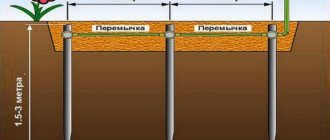
Schematically, this system looks like this:
The most commonly used grounding scheme for a private house
The location of the buried electrodes is chosen so that it is as convenient as possible to bring the grounding bus to the distribution panel. The optimal distance from the house is 3-6 meters. Acceptable limits are no closer than one meter and no further than ten.
The dimensions indicated in the diagram are by no means some kind of dogma. So, the side of the triangle can be up to three meters in length, and the depth of driving the pin can be slightly smaller - 2.0 ÷ 2.5 m. The number of electrodes can also change - if the soil is dense and it is not possible to drive the pins to a greater depth, you can increase their number.
A good idea is to contact your local utility company in advance for recommendations on how to install a ground loop. These specialists probably have well-thought-out schemes that have been tested in this region. In addition, they will be able to help calculate the dimensions based on the planned load of the home electrical network - this also matters.
Rolled metal that can be used for buried electrodes
What can serve as electrodes? For these purposes, a steel corner with a shelf of 50 × 50 mm and a thickness of at least 4 ÷ 5 mm is most often used. Pipes can be used, preferably galvanized ones with a wall thickness of at least 3.5 mm. You can take a steel strip with a cross-sectional area of about 48 mm² (12 × 4), but it is more difficult to drive it vertically into the ground. If you decide to use a steel rod, then it is also better to take a galvanized one with a diameter of at least 10 mm.
To tie the pins into one circuit, use a 40 × 4 mm strip or 12 - 14 mm wire rod. The same material is suitable for laying a grounding bus to the point of its entry into the house.
- So, initially markings are made at the selected location.
Pit and trench for ground loop
- Then it is advisable to dig a small pit of the intended shape to a depth of 1 meter. The minimum depth is 0.5 m. At the same time, a trench is dug to the same depth - a grounding bus will go along it from the contour to the base of the house.
You don’t have to dig a pit, but limit yourself to digging trenches
- The task can be somewhat simplified by digging not a solid pit, but only trenches along the perimeter of the contour being created. The main thing is that their width allows free driving of electrodes and welding work.
The edges of the corners need to be cut and sharpened so that they fit into the ground more easily.
- Electrodes of the required length are prepared. The edge with which they will be driven into the ground must be sharpened with a grinder, cutting it at an angle. The metal must be clean and unpainted.
The electrodes are sequentially driven into the ground to the required depth.
- At the designated locations, the electrodes are driven into the ground using a sledgehammer or electric hammer. They are buried so that in the pit (trench) they protrude above the surface level by about 200 mm.
Electrodes are connected by welding with a steel strip
- After all the electrodes are clogged, they are connected with a common busbar (horizontal grounding conductor) made of a 40 × 4 mm metal strip. Only welding is applicable here, although you can find recommendations to use a bolted connection. No, to ensure reliable and durable grounding, this harness must be welded - a threaded contact placed underground will quickly oxidize, and the circuit resistance will increase sharply.
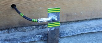
The busbar is welded to the circuit and routed to the base of the building
- Now you can lay a bus from the same strip to the foundation of the house. The tire is welded into one of the clogged electrodes and placed in a trench, then it goes onto the base of the building.
- The busbar is attached to the base. Not shown in the figure, but it is advisable to provide a small bend in front of the attachment point, the so-called “compensation hump,” to compensate for the linear expansion of the metal during temperature changes. A bolt with M10 thread is welded at the end of the strip. A copper terminal with a grounding wire will be attached to it, which will go to the distribution panel.
Terminal transition to ground wire
- To pass the wire through the wall or through the base, a hole is drilled and a plastic sleeve is inserted into it. The wire used is copper, with a cross-section of 16 or 25 mm² (it is better to check this parameter with specialists in advance). It is also better to use copper nuts and washers for connections.
In this case, the grounding bus from the fittings is brought inside the room
- Sometimes they do it differently - a long steel pin is welded to the tire, so that it passes right through the wall of the house, also through the sleeve. In this case, the terminal part will be indoors and will be less susceptible to oxidation under the influence of high air humidity.
Bronze distribution plate for connecting ground wires
- The grounding wire is connected to the electrical distribution panel. For further “distribution”, it is best to use a special plate made of electrical bronze - all the grounding wires going to the points of consumption will be attached to it.
Upon completion of installation, it is necessary to check the functionality of the system.
Do not rush to immediately fill the installed circuit with soil.
— It is recommended, firstly, to capture it in a photograph with reference to surrounding stationary ground objects - this may be required to make changes to the design documentation, as well as to carry out control and verification activities in the future.
— Secondly, it is necessary to check the resistance of the resulting circuit. For these purposes, it is better to invite specialists from the energy supply organization, especially since their call, one way or another, will be necessary to obtain permits.
If the test results show that the resistance is high, it will be necessary to add one more or even more vertical electrodes. Sometimes, before checking, they resort to tricks by generously watering the areas around the corners hammered into the ground with a saturated solution of ordinary table salt. This will certainly improve the performance, however, do not forget that salt activates metal corrosion.
Ordinary table salt significantly reduces the circuit resistance, but, alas, activates metal corrosion
By the way, if it is not possible to hammer in the corners, then they resort to drilling wells to the required depth. After installing the electrodes, they are filled with clay soil as densely as possible, which is also mixed with salt.
After the functionality of the grounding loop has been checked, it is necessary to treat the welds with an anti-corrosion compound. The same can be done with the bus going to the building. Then, after the mastic has dried, the pit and trenches are filled with soil. It must be homogeneous, not littered and free of crushed stone inclusions. Then the backfill area is carefully compacted.
Video: installation of a grounding loop using a metal corner
Using ready-made factory kits
Ready-made factory-made kits are very convenient for organizing grounding at the dacha. They are a set of pins with couplings that allow you to increase the depth of immersion into the ground as you drive.
Single pin grounding system
This grounding system provides for the installation of one pin electrode, but to a greater depth, from 6 and even up to 15 meters.
The kit usually includes:
- Steel pins 1500 mm long with a galvanized or copper-plated surface, or made of stainless steel. The diameter of the pins may differ in different sets - from 14 to 18 mm.
Set of rods for assembling the grounding electrode
- To connect them, they are equipped with threaded couplings, and for ease of penetration through the ground, a steel tip is included in the kit.
Threaded coupling and ferrule for easy driving
In some kits, the couplings are press-fit rather than threaded. In this case, one end of the ground rod is tapered by forging and has a ribbed surface. When impacted, a strong connection occurs and reliable electrical contact is achieved between the rods.
The pins can also have a press-fit coupling
- To transmit the impact, a special attachment (dowel) made of high-strength steel is provided, which will not be deformed by the impact of the hammer.
Dowel - a nozzle that will transmit the impact force from the hammer
- Some kits include a special adapter that allows you to use a powerful hammer drill as a driving tool.
Hammering the electrode using a hammer drill
To install such a grounding system, it is also advisable to dig a small pit up to a meter deep and the same in diameter, although some even prefer external placement.
Growing the electrode as it is driven into the ground
The pins are driven in sequentially and incrementally to the required depth.
Then a brass contact clip is put on the area left on the surface (about 200 mm).
Either a metal bus or a ground wire can be inserted into such a contact clamp
Either a conductive busbar made of a metal strip is inserted into it, or a grounding cable with a cross-section of 25 square meters is inserted. mm. For connection to the steel strip, a special gasket is provided, which does not allow for electrochemical contact between the ground of the rod and the steel (zinc). Subsequently, the bus or cable is brought into the house and connected to the distribution panel in exactly the same way as described above.
Video: manually driving pin electrodes
Prices for components for lightning protection and grounding
Components for lightning protection and grounding
What type of rod coating should I choose – galvanized or copper-plated?
- From an economical point of view, galvanizing with a thin layer (from 5 to 30 microns) is more profitable. These pins are not afraid of mechanical damage during installation; even deep scratches left do not affect the degree of protection of the iron. However, zinc is a fairly reactive metal, and while protecting the iron, it oxidizes itself. Over time, when the entire zinc layer has reacted, the iron remains unprotected and is quickly “eaten up” by corrosion. The service life of such elements usually does not exceed 15 years. And making the zinc coating thicker costs a lot of money.
Comparative test: galvanized (left) and copper-plated (right) electrode after 10 years of operation in an aggressive acidic soil environment
- Copper, on the contrary, without reacting, protects the iron it covers, which is more active from a chemical point of view. Such electrodes can serve for a very long time without compromising efficiency; for example, the manufacturer guarantees their safety in loamy soil for up to 100 years. But during installation, care should be taken - in places where the copper plating layer is damaged, a corrosion area will likely appear. To reduce the likelihood of this, the copper plating layer is made quite thick, up to 200 microns, so such pins are much more expensive than conventional galvanized ones.
What are the general advantages of such a set of grounding systems with one deeply placed electrode:
- Installation is not particularly difficult. No extensive excavation work is required, no welding machine is needed - everything is done with ordinary tools that are found in every home.
- The system is very compact; it can be placed on a tiny “patch” or even in the basement of the house.
- If copper-plated electrodes are used, then the service life of such grounding will be several tens of years.
- Thanks to good contact with the ground, minimal electrical resistance is achieved. In addition, the efficiency of the system is practically not affected by seasonal conditions. The level of soil freezing accounts for no more than 10% of the length of the electrode, and winter temperatures cannot in any way negatively affect the conductivity.
There are, of course, some disadvantages:
- This type of grounding cannot be implemented on rocky soils - most likely, it will not be possible to drive the electrodes to the required depth.
- Perhaps some will be put off by the price of the kit. However, this is a controversial issue, since high-quality rolled metal for a conventional grounding scheme is also not cheap. If we also add the duration of operation, simplicity and speed of installation, and the absence of the need for specialized tools, then it is quite possible that this approach to solving the grounding problem may seem even more promising from an economical point of view.
Video: how to ground your home using a modular pin system
Rules, regulations and basic requirements of the PUE
It's time to get acquainted with the basic requirements for grounding systems in private homes. The main parameter is the loop resistance, which determines the reliability and efficiency of the system.
The lower the resistance of grounding devices, the higher their reliability.
Ohm's law states that the current in a section of a circuit is directly proportional to the voltage and inversely proportional to the electrical resistance of a given section of the circuit.
Thus, the lower the resistance, the greater the likelihood of the ground loop tripping.
For most residential buildings with 380V and 220V electrical networks, the resistance should not exceed 30 ohms. Moreover, if the house is equipped with a gas boiler, then the resistance should not exceed 10 ohms.
The Electrical Installation Rules (PUE) determine that every residential property within the city must be equipped with special measures to protect against dangerous voltages. We are talking specifically about metal grounding loops, which guarantee protection of residents from electric shock.
Chapter 1.7, part 1, paragraph 1.7.72 of the PES states that the dimensions of metal elements are selected taking into account the final resistance indicator (mentioned above), and the parameters of each structural element may differ in their characteristics.
The minimum size requirements are still strictly defined:
- Connecting strip - no less than 12x4 mm (section no less than 48 sq. mm).
- Pins (metal corner) - metal thickness is at least 4 mm.
- Round reinforcing pins - cross-sectional area of at least 10 sq. mm.
- Metal pipes - wall thickness of at least 3.5 mm.
At first glance, all this information may seem too complicated and even unnecessary. Nevertheless, information about the characteristics of the grounding loop and the equipment used on the site will protect residents and animals by preventing network overload.
Purpose of calculating protective grounding
The grounding device installed on the consumer side is designed to protect not only personnel servicing electrical installations, but also ordinary users.
Important! Dangerous potential can reach metal parts of equipment while working with it completely accidentally (due to damage to wire insulation, for example).
A complete grounding calculation guarantees the formation of reliable contact of the protective device with the ground, leading to the spreading of current and a reduction in the level of dangerous voltage.
Thus, the purpose of calculating grounding devices is to create conditions that eliminate the risk of damage to living organisms by high potential by reducing it at the point of closure. In the absence of a well-designed and functional grounding conductor, any touch to the frame of damaged equipment is tantamount to direct contact with the phase conductor.
Technical requirements for ground loop resistance
Now that we’ve sorted out the theory, we can move on to analyzing the technical component of this issue. For private houses, it is first worth studying Chapter 1.7 of the PEU, which regulates the installation of grounding loops in networks up to 1000V. This category includes all residential private houses, so when selecting components you need to be guided by this standard.
According to this document, resistance can reach several indicators:
- Up to 0.5 Ohm for electrical installations with voltages over 1000 Volts with high ground fault currents (more than 500 A).
- Up to 4 Ohms for installations up to 1000 Volts (the category of private houses, dachas, cottages we need).
- No more than 10 Ohms for electrical installations with voltages over 1000 V and small ground fault currents.
- No more than 10 Ohms, if the total total power of electrical installations does not exceed 100 kVA.
This is what the regulatory documentation looks like, allowing you to select the correct parameters of grounding loops when selecting materials and components for their installation. Now let's move on to studying the structures themselves, which make it possible to effectively drain large fault currents into the ground.
Why is grounding needed?
When a short circuit occurs, the temperature of the conductor will rise sharply, causing melting of both the insulation and the conductive strands themselves. If you touch the wires at the moment of a short circuit, current will flow through the body, which can be fatal. This happens because the current always tends to follow the path of least resistance - that is, into the ground.
Grounding is a path that directs electricity directly to the ground, where it cannot harm anyone. The current always chooses the path with minimal resistance, and the ground loop has exactly this property. When a power leak occurs, the excess is immediately sent to the ground loop. Thus, even if a person receives an electric shock, it will not be severe, since most of the electrical energy will go through the grounding system.
It turns out that grounding is an important component of the electrical safety system. It must be said that grounding is a necessary part of any objects that use electricity. According to the requirements of regulatory documents, any building containing alternating current networks with voltages over 100 W must be equipped with a grounding system.
Grounding not only ensures safety, but also protects household appliances. The grounding loop takes on excess load during network fluctuations, reduces the impact of interference and neutralizes the negative effects of electromagnetic radiation.
Types of circuits and grounding schemes
The rate at which current is drained into the ground directly depends on the efficiency of the system itself. Grounding connections are structurally very similar to lightning rods, since they perform the same task, but this also applies to the technical component.
The more electrodes that simultaneously remove the electrical charge, the less time it will take.
There are three types of grounding:
- Modular-pin is the simplest type of circuit, which is an analogue of a lightning rod in the form of a single electrode going deep into the earth. Due to low efficiency and narrow application due to differences in soil hardness, it is practically not used. Despite this, this option is much more effective than the complete absence of grounding in the house or country house.
- Linear is a compromise solution, since the efficiency of an open loop is much lower than that of a closed loop. However, if you do not have the required amount of space, a linear outline can greatly save the situation. Technically, it represents a chain of electrodes located on the same line or in a circle at a distance of 1-1.5 units relative to the length of the electrode. For greater efficiency, you will have to increase the tapping points.
- A closed circuit (triangle) is the most effective method of protection against short circuits and voltage surges in the network. The closed triangle allows large leakage current to be quickly and efficiently removed without the need to deepen the electrodes to great depths. The rigid connection of the pins can significantly improve the quality and efficiency of the circuit, while the circuit can significantly reduce installation costs.
Let's look at the last option, since it is recommended to use this option in private residential buildings, dachas or cottages.
The design is quite simple, you will need:
- Three pointed rods of equal length - 2-3 meters.
- Three connecting strips of equal length - 1.2-1.5 meters.
These components are connected to form an equiangular triangle, with one pin extending from each vertex. For connection, it is best to use electric welding, which will turn all components into a reliable monolithic ground loop.
We considered the necessary parameters of each element at the beginning of this article, so now it is worth mentioning the depth and dimensions of the triangle.
The minimum depth is 0.5 meters, but if possible it is worth increasing this parameter. The length of the pins is within 2-3 meters, while the distance between them in the finished structure varies from 1.2 m to 1.5 meters, at your discretion.
It is worth digging such a circuit in any convenient place near a residential building to the depth indicated above. If you are strictly limited in area, you should pay attention to other grounding schemes. Remember - ineffective grounding is better than no grounding at all.
Visually about grounding theory
Let's start with a clear example - where there is a grounding circuit with a single vertical ground electrode buried in the ground. It is connected to a metal cabinet, or to the body of any electrical appliance in which a short circuit has occurred. Namely, the phase is closed to the body - the wall of the cabinet. For simplicity, we define the initial conditions:
- A short circuit “in its pure form” is a metal conductor to the metal body of an electrical appliance. Therefore, side values such as contact resistance can be ignored.
- We also do not take into account the resistance of the horizontal ground electrode or the conductor to the electrical appliance, since for large cross-sections it is negligible.
We further assume that the soil in the area of the ground electrode has the same composition and equal properties in all directions. In this case, the current will flow into the ground equally in all directions:
- Near the ground electrode there is the highest current density.
- Moving away from the ground electrode, the current density gradually decreases.
As a result, with distance from the ground electrode, the resistance to current propagation also decreases, since it flows through the ground - a conductor that is constantly growing in its “cross-section”. And the voltage is highest on the ground electrode, and as it moves away, according to Ohm’s law, it also gradually decreases. Obviously, at a certain distance from the ground electrode, the voltage will be insignificant - it will be so close to zero that it can be neglected. Such a point - with negligible voltage - is the so-called point of zero potential. In principle, it is the very ground to which the electrical appliance cabinet is connected for safe operation.
1.7.20 Zero potential zone (relative earth) is a part of the earth located outside the ground electrode zone, the electric potential of which is assumed to be zero.
At the same time, it is important to understand
:
- That the resistance of the grounding device has nothing to do with the resistance of its material (metal) - it is insignificant.
- And this is not resistance when the metal of the ground electrode comes into contact with the ground - to reduce it, certain requirements are deliberately met.
This is the resistance from the ground electrode itself to the zero potential zone
.
And the resistance of the grounding device is the quotient of the phase voltage supplied to the cabinet as a result of a short circuit and the strength of its current. This is the basis for further calculations.
Rз: Uф / Iкз.
However, to comply with the requirements of the grounding device PUE - rules for electrical installations, with a high probability, the resistance parameters of a single ground electrode are simply not enough. How to obtain values sufficient for safe operation?
One of the main factors is the surface area of the ground electrode. But its increase will inevitably require an increase in its cross-section, which means an increase in the cost of both the ground electrode itself and the work to bury it. It turns out that the simplest solution is to add another electrode. It is important that it makes no sense to bury them side by side - in this case, the current spreads as if from one electrode, which does not provide dramatic improvements.
The current flow configuration can be changed by removing the grounding electrodes to a significant distance from each other. Then they will divide the current - it will flow from each individual grounding electrode. However, this will reveal a new problem - in order to achieve a simple “parallel connection” of their resistances, the electrodes must be spaced very far apart. What is difficult to implement in reality is that the grounding device will take up a huge area.
Therefore, grounding electrodes are placed more compactly, which inevitably results in the formation of an intersection zone of currents emanating from different electrodes. To take into account their mutual influence and compensate for the error in calculating the distance from each other, a so-called correction coefficient is used.
Moreover, the resistance of the grounding loop can be effectively reduced by simply increasing the length of the grounding electrodes with greater depth. This increases the surface area in contact with the ground, which stimulates the spread of current.
The effect is perfectly realized in practice - in grounding kits made of copper-plated steel electrodes. The depth required for grounding parameters is achieved by splicing the pins. As it goes deeper into the ground, the next electrode is screwed onto the threaded coupling of the previous one, forming a single vertical ground electrode.
At the same time, the influence of the horizontal grounding device is taken into account - a connection that unites all vertical electrodes into one grounding device, and also reduces its total resistance. The horizontal connection is shielded by vertical grounding conductors.
Table
: shielding coefficients of vertical electrodes made of pipes, angles or rods placed along the contour.
| The ratio of the distances between vertical electrodes to their length | Number of vertical electrodes in the circuit | ||||||||
| 4 | 6 | 8 | 10 | 20 | 30 | 50 | 70 | 100 | |
| 1 | 0,45 | 0,40 | 0,36 | 0,34 | 0,27 | 0,24 | 0,21 | 0,20 | 0,19 |
| 2 | 0,55 | 0,48 | 0,43 | 0,40 | 0,32 | 0,30 | 0,28 | 0,26 | 0,24 |
| 3 | 0,70 | 0,64 | 0,60 | 0,56 | 0,45 | 0,41 | 0,37 | 0,35 | 0,33 |
A system is formed from individual components and factors influencing each other:
- Number of grounding electrodes.
- Removal between them, at what depth they are laid.
- The surface area formed by the profile shape - rod, pipe, angle.
- Horizontal connection parameters – shape and length.
As you can see, there are quite a lot of conditions. Therefore, it will not be possible to calculate the grounding device using only one formula - the result will be incorrect. What other definitions and quantities affect the calculation of grounding?
Touch voltage and step voltage
Let's return to the electrical appliance presented in the example with a short circuit of a phase to its body.
Even touching it, a person still has significantly greater electrical resistance than the piece of land where he is located, so a relatively small current flows through it.
The danger is that in this case the person stands precisely in the zone of spreading of the short circuit current. This is the reason for the occurrence of electrical voltage between parts of the human body in contact with the surfaces. Moreover, these may not necessarily be limbs (although most often they are arms and legs), but you can simply lean against the cabinet of an electrical appliance. As a result, the tension received by a person through the points of contact is the tension of touch.
1.7.24 Touch voltage is the voltage between two conductive parts or between a conductive part and the ground when simultaneously touched by a person or animal.
They try to reduce it as much as possible - to adjust it to the established standards. The permissible parameters of the grounding device are calculated based on them.
For clarity, we will consider only one ground electrode. Let's understand the processes on the very surface of the earth:
- Near the electrode – maximum voltage.
- As you move away, it gradually decreases.
- And reaches a certain distance, where potential = 0.
If points of equal potential are abstractly combined around the grounding electrode, then similarities of circles will appear. Another name for them is equipotential lines.
If the ground electrode conducts a short circuit current, then the person walking towards this electrode also receives some part of the electrical voltage through his feet - a potential difference depending on the position of his legs (the distance from the electrode of each foot). This is a manifestation of the tension in the step.
1.7.25 Step voltage is the voltage between two points on the earth's surface, at a distance of 1 m from each other, which is taken to be equal to the length of a person's step.
In electrical installations where instantaneous interruption of ground fault current is provided, it is not particularly dangerous. In a short period of time (within a few seconds), a person can feel unpleasant effects, and that’s all.
In electrical installations where the earth fault current can be present for a long period of time, restrictions apply. Therefore, step voltage is a relevant concept for electrical safety, especially when it comes to approaching live parts connected to the ground in open and closed switchgears. The minimum permissible approach distance to them is 8 and 4 meters, respectively.
It is clear that so that people do not get hurt - they try to minimize the stress of touch and step.
In principle, all PUE standards were developed and published for the same purpose - for the safety of practical use.
Natural grounding
Of course, first of all, natural grounding should be used for protection. These are underground communications made of metal (excluding pipelines of flammable substances), metal structures of buildings connected to the ground, cable sheaths, casing pipes of wells, wells, pits.
1.7.17 Natural grounding - a third-party conductive part that is in electrical contact with the ground directly or through an intermediate conducting medium, used for grounding purposes.
And provided that the spreading resistance of natural grounding conductors meets the standards, the manufacture of artificial grounding conductors is not required. But it should be taken into account that it can only be measured; it is impossible to calculate the resistance of natural grounding conductors in advance. And in the absence of natural grounding conductors, or their parameters are unsatisfactory, man-made – artificial grounding conductors are used.
DIY grounding installation in a private house
We proceed directly to the process of installing the grounding loop on the site.
To make a ground loop with your own hands you will need:
- Angle grinder for cutting and cleaning seams.
- Wrenches M12 and M14.
- Bayonet shovel for digging a trench to the installation site of the circuit.
- A sledgehammer for deepening current-carrying pins.
- Welding machine for assembling the structure.
In addition, depending on the soil, you may need a crowbar or a hammer drill. They can come in handy when you come across a rock while digging trenches.
Now let's devote a few more words to a set of materials for making a ground loop.
List of required materials:
- Metal corner 50x50 mm with a metal thickness of 5 mm - 3 pieces of 3 meters each.
- Steel strip 40 mm thick 4 mm - 12 meters (for one grounding point).
- Bolts M12 or M14 with washers and nuts - 2 pcs.
- The copper conductor for diverting the circuit from the building is a copper cable with a cross-section of 6-10 sq. mm.
Do not use corrugated reinforcement or round steel with a diameter of less than 10 mm as grounding conductors. The minimum requirements for a grounding conductor is a corner 40x40x5 mm or a steel circle with a diameter of 14 mm.
All of the above will allow you to assemble a high-quality and reliable grounding circuit that will protect your loved ones and the entire house from electrical troubles.
Before deepening the pins, it is worth sharpening one of their edges; the best option would be an angle of at least 30 degrees. This will make it much easier to bury the corner into the ground.
We proceed directly to the excavation work.
To simplify driving in the pins, you can create three vertical holes using a drill, and only then drive the ground electrodes into the ground. Do not forget that the entire structure must be buried 0.5 meters into the ground, accordingly, all parameters must be calculated starting from this depth, and not the surface of the earth.
After driving the pins, you can start welding all the components into a monolithic structure. Due to the equal length of the steel strip segments, you will end up with an isosceles triangle in any case. Don’t forget to position it so that one of the vertices “points” to the house itself; it is from this that you need to take the remaining strip for connecting with the house wiring.
We will also give you some tips - it is best to buy materials with a reserve, based on the maximum length indicated above. This will allow you to reinsure yourself, while the pins may become deformed during the driving process, and accordingly reduce their length. It is also worth doing with the metal strip, since the dimensions may change when welding or cutting.
Common installation errors
Owners of country houses, when independently installing grounding structures, often make the following mistakes:
- The electrodes are covered with a layer of paint and varnish material to protect the product from corrosion. As a result, such a coating prevents the flow of current into the ground.
- Bolt the grounding pins to the metal connections. As a result of corrosion, structural elements lose contact with each other.
- The triangular outline is placed far from the foundation of the building. This leads to a significant increase in the resistance of the grounding system.
- Aluminum and copper conductors are used simultaneously. In this case, due to contact corrosion, the connection of the elements deteriorates.
- A very thin profile is used for electrodes. As a result of the formation of corrosion, the resistance of the metal product increases significantly.
If any deficiencies are found in the system, it is recommended to eliminate them immediately. A malfunctioning grounding device is unable to provide reliable safety to owners of private houses that use household electrical equipment.
Ready-made kits or manual assembly?
Many owners who decide to make a grounding loop with their own hands may have a reasonable question: isn’t it easier to use ready-made grounding kits?
No, it’s not simpler; more precisely, it’s not always simpler, and sometimes even more expensive. Ready-made kits are a compromise solution, since with time savings you get a higher cost, but the quality of the materials is not always the same.
Most stores sell modular or linear circuits, which are relatively cheaper, but do not always provide the proper quality of electrical conductivity.
By independently selecting and connecting all the components, you will be 100% confident in the quality of the grounding circuit, and therefore in the safety of the entire house. But you shouldn’t give up ready-made kits - they are perfect for arranging a small dacha or cottage, garages and utility rooms equipped with an electrical network.
Before you bury the entire structure, it is necessary to paint the visible part of the contour for reliable protection against corrosion. It is best to clean the entire plane of the elements, since poor preparation before painting will lead to accelerated corrosion of the metal.
After completing all installation work, you need to bury the trenches. Another tip is that before digging, you can fill the fresh soil with a saline solution, which increases the conductivity of the circuit. To prepare it, follow the proportion of 2-3 kg of salt per 10 liters of water. Afterwards, you need to carefully compact the soil for better contact with the contour; low density has a negative effect on soil resistance indicators.
Nuances and pitfalls in using a ground loop
No matter how well you calculate the quantity and quality of materials, there are nuances that do not depend on them, but every homeowner should know about this.
First of all, we are talking about the resistance of the soil itself, because it varies depending on its characteristics. For example, the resistance of peat is only 20 Ohms per 1 cubic meter, but the values of sand can reach 1000 Ohms per 1 cubic meter. Chernozem and clay practically do not differ in their characteristics; their resistance per 1 cubic meter is 50 Ohms and 60 Ohms, respectively.
Also, the level of resistance is influenced by the depth of the water horizon; the closer it is to the surface, the lower the soil resistance. Be sure to take into account the exact type of soil in your region and determine at least approximate resistance values, so you will be confident in the quality of the grounding.
So, we have examined all the important features and requirements for grounding loops for private houses. If you did not know how to properly make a grounding loop, all the diagrams, features and specifics of the installation process of such systems are discussed here.
How to check the ground loop after installation?
All the actions described below must be carried out before backfilling the trenches, so do not rush; a repeated check will allow you to be even more confident in the reliability of the structure.
First of all, carry out a visual inspection:
- Check the joints of the elements for the quality of welding, as well as the presence of cracks.
- Examine for any signs of damage to the connecting wire and metal strip.
- Inspect the quality of painting of the elements and, if necessary, correct damaged areas.
Using the same principle, it is necessary to carry out annual monitoring of the condition of the grounding loop of a private house. Thanks to this, it will work for many years, without the need to replace elements.
In addition, it is worth paying attention to periodic checks of the physical parameters of the circuit, such as resistance. The PEU states that the total resistance of all repeated groundings at any time of the year should not exceed 10 and 20 Ohms for networks with voltages of 380 V and 220 V, respectively. At the same voltages, the resistance of each individual grounding element should not exceed 30 Ohms and 60 Ohms for networks of 380 V and 220 V, respectively.
Be sure to remember - in addition to compliance with technical parameters, the grounding circuit must meet all the requirements of GOST and PEU standards regulating this issue. Only complete compliance with them will allow you to be 100% confident in the operation of grounding for a private home.
The final stage is introducing grounding into the house
Although we have already sorted out all the street work on organizing the grounding loop, we still need to think about connecting the electrical wiring and the grounding loop.
For connection you need to use the same bus as for connecting conductors. It is best to try to “reach” the metal bus directly to the electrical panel, but if this fails, you should do it at least from the outside of the house, and then connect it using a copper wire with a cross-section of 6-10 mm2.
If it seems to you that everything is so simple, do not forget that there are several connection schemes - TN-CS and TN-S.
The TN-S circuit is the most modern and reliable type of electrical wiring. This scheme is compatible with transformers with a solidly grounded neutral, while the N and PE conductors are separated along the entire line from the substation to the consumer. This option involves the use of a five-core cable, which ensures maximum efficiency and safety.
The TN-CS circuit is an excellent option for organizing grounding on a temporary basis. Based on this diagram, the neutral conductor N intersects the conductor PE, and in this case several grounding points are necessary. A common wire PEN is drawn from the substation, which is divided into PE and N at the supply to the residential building. Most often, such schemes are used in areas of new buildings, or in the absence of a modern electrical network in the region. In the latter case, it is necessary to wait for the installation of a full five-wire system by electrical services.
The main disadvantage of the second option is the need to lay the wiring with a three-core cable, which will still have to be replaced with a more reliable five-core cable. Also, if it is necessary to connect a three-phase 380V network, you must use the same five-core cable. Based on all this, it turns out that the cost of installing wiring according to this scheme is economically unprofitable.
If you initially take care of installing the correct type of wiring, implementing grounding will not be a problem for you. In addition, the use of a five-wire line will allow you to save significantly, since you will not have to re-install electrical networks in your own home.
Tags:
- electrical installation
Rate the material: