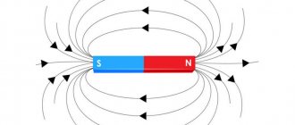
Definition.
A TN-C system is a power distribution system in which one of the live parts of the power supply is grounded. The exposed conductive parts of the electrical installation of the building are connected to the grounded part of the power source, which is energized, by means of PEN conductors, PEM conductors or PEL conductors (definition based on SP 437.1325800.2018).
All the information you read below is almost entirely based on articles by Yu.V. Kharechko from his book [1], as well as regulatory documentation [2] and [3].
The essence of grounding
Why do you need grounding if everything works fine without it? Moreover, in normal operation no current flows through the protective ground wire at all.
The key word here is “protective”. Who does grounding protect and from what? It protects human bodies from the effects of electric current. And what it protects against is to ensure that dangerous voltage does not appear on the human body under any circumstances, and that current does not flow through the person.
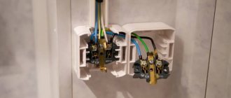
Let's imagine the situation. There is some electrical appliance, for example an iron. The iron is connected through this plug.
Old plug without grounding pin
Older readers remember these very well; they were constantly unwinding, and attaching a flexible wire to them was a pain.
The body of the iron is partially metal. What happens if a phase suddenly gets on the body? In principle, nothing, the iron can even continue to work. But its body will be at a potential of 220V relative to ground. And since we all walk on the earth, if we touch the metal body of such an iron, current will flow through us.
And then - depending on your luck. If the skin and floor are dry, it will just tug a little...
But if the body of the iron is grounded, then when the phase wire hits the body, it will connect to the ground and go into the ground. In this case, an actual short circuit will occur and the circuit breaker of this line will be knocked out. And the body will remain as it was at zero potential.
In other words, if a phase suddenly gets onto the body of the device, this is no longer a human problem. This is a problem with the device itself and the circuit breaker, which must disconnect this device from the phase wire.
Why does the circuit breaker turn off? If the phase wire touches the protective (grounding) conductor, this is equivalent to a short circuit, that is, the maximum possible current in the circuit. And the machine will work due to electromagnetic protection.
Let me remind you that there is a time-current characteristic of the circuit breaker, and during a short circuit the circuit breaker will operate in the right zone of the characteristic, where the shutdown time tends to zero. Read more in my article about choosing a circuit breaker.
That is, the current in the protective grounding wire flows only at the moment of an accident, the rest of the time it is useless. Therefore, they used to save on it and use a two-wire power system, in which there is only zero and phase.
IT grounding circuit
The system is used exclusively in mining areas, such as mines or quarries. The peculiarities of using electrical equipment at such enterprises are such that it is simply impossible to provide a high-quality protective circuit there.
Only the neutral of the transformer is grounded with the help of control and measuring instruments that perform the functions of protection against electrical leakage. If the devices detect excess energy consumption, an emergency shutdown of the devices occurs.
The main purpose of grounding is to make the use of electrical appliances safe, as well as to extend their service life. Do not neglect the design and construction of grounding; this is an unjustified risk.
Designations and translation of names of grounding systems
There are TN, TT and IT grounding systems. The TN system, in turn, is used in three different versions: TN-C, TN-S, TN-CS. The first letter indicates the method of grounding the source of electrical energy (generator or transformer), the second letter indicates the method of grounding the consumer.
Types of grounding systems
These letters come from French and mean: “Terre” - earth, “Neuter” - neutral, “Isole” - isolate, and also from English: “Combined” and “Separated” - combined and separate.
- T - wire connected to ground.
- N - connection to neutral.
- I - isolation.
- C - combination of functions, connection of the working and protective neutral wires.
- S - separate use of working and protective neutral wires throughout the entire network.
The following designations are also used in grounding system diagrams:
- L – Line, The line on which the phase voltage operates in relation to the neutral wire.
- N – Neutral, working zero, through which an operating current flows equal to the current in wire L (for single-phase systems).
- PE – Protect Earth, protective earth, protective ground wire.
- PEN is a combined working and protective neutral conductor.
Isolated Neutral Systems
In all the systems described above, the neutral is connected to ground, which makes them quite reliable, but not without a number of significant drawbacks. Much more advanced and safer are systems that use an insulated neutral that is completely unconnected to ground, or grounded using special devices and devices with high resistance. For example, as in the IT system. Such connection methods are often used in medical institutions to power life-support equipment, at oil refining and energy plants, scientific laboratories with particularly sensitive instruments, and other critical facilities.
IT system
IT grounding system
The classic system, the main feature of which is the isolated neutral of the source - “I”, as well as the presence of a protective grounding circuit on the consumer side - “T”. Voltage from the source to the consumer is transmitted through the minimum possible number of wires, and all conductive parts of the consumer equipment housings must be reliably connected to the grounding electrode. There is no zero functional conductor N in the source-consumer section in the IT system architecture.
Brief description of the operation of grounding systems
Grounding systems are primarily characterized by safety. That is, how many chances to survive does such a system give a person after a phase appears on the body.
There is confusion in terminology - I call the same system both grounding and grounding. Wikipedia suggests calling TN systems grounding on the grounds that in them the grounding conductor PEN is connected to the zero (neutral) wire of the power source. And this wire in the transformer is already grounded. Grounded to prevent phase imbalance.
Read more about phase imbalance, why it is dangerous, and how to deal with it in my other article.
PUE, the Electrician's Bible, talks about the same thing as grounding systems.
You can download my PUE here, in different versions.
The difference between these concepts, in my opinion, is very vague. In my opinion, grounding is necessary to maintain the voltage at ground potential on the PE wire and on all non-current-carrying parts of the electrical installation to which it is connected. And grounding is necessary to create a short circuit current when a phase is shorted on the same parts of the electrical installation. As a result, there can be only one effect - grounded or neutralized parts will never be under phase voltage, and the circuit breaker should operate. This is short and in your own words.
In general, grounding is a broader concept than grounding.
We can say that the protection system is as safe as this point is close to the voltage source. And again, what can be considered a consumer - an electric kettle, an apartment, a multi-story building, or a city district?
Well, if the phase “breaks through” onto the body, it should be destroyed by the protective circuit breaker with 100% probability.
I think two things are important here:
- All metal that is out of phase must be at the same potential. And it is desirable that this potential be equal to the potential of the earth. This is the “zero” potential.
- Dangerous - inaccessible. Accessible - safe. It happens that you look at the Soviet apartment shields or RP and your hair moves.
And again, I will repeat again. The probability of a break in the neutral working conductor is always considered. The fact is that with such a break, phase voltage is present throughout the entire circuit of the device, up to the zero break point.
I write about this in detail in an article about zero break in single-phase and three-phase circuits.
In the event of a touch, the current passes through the load and through the human body. Despite the load resistance, this current remains as dangerous as when touching a phase wire. After all, the load resistance (for example, an electrical household appliance) is always much less than the resistance of the human body.
Installation of a ground loop in a private house
Calculations can be viewed at the link.
or (of course, depends on the soil, but also an option)
How to hammer into reinforcement or a grounding rod with a hammer drill? or
According to clause 1.7.54 of the PUE, artificial and natural grounding conductors can be used for grounding electrical installations. If, when using natural grounding conductors, the resistance of the grounding devices or the touch voltage has an acceptable value, and the normalized voltage values on the grounding device and the permissible current densities in natural grounding conductors are ensured, the implementation of artificial grounding conductors in electrical installations up to 1 kV is not necessary.
The use of natural grounding conductors as elements of grounding devices should not lead to their damage when short-circuit currents flow through them or to disruption of the operation of the devices with which they are connected.
The following can be used as natural grounding conductors (clause 1.7.109 of the PUE):
- metal and reinforced concrete structures of buildings and structures in contact with the ground, including reinforced concrete foundations of buildings and structures with protective waterproofing coatings in non-aggressive, slightly aggressive and moderately aggressive environments;
- metal water pipes laid in the ground;
- casing pipes for drilling wells;
- metal sheet piles of hydraulic structures, water conduits, embedded parts of gates, etc.;
- rail tracks of main non-electrified railways and access roads in the presence of a deliberate arrangement of jumpers between the rails;
- other metal structures and structures located in the ground;
- metal shells of armored cables laid in the ground. Cable sheaths can serve as the only grounding conductors when there are at least two cables. Aluminum cable sheaths are not allowed to be used as grounding conductors.
The following are not allowed to be used as grounding conductors:
- pipelines of flammable liquids, flammable or explosive gases and mixtures;
- sewerage and central heating pipelines.
The specified restrictions do not exclude the need to connect such pipelines to a grounding device for the purpose of equalizing potentials in accordance with 1.7.82.
Artificial grounding conductors can be made of black or galvanized steel or copper, and should not be painted.
The method of installation of vertical grounding conductors depends on the following factors:
- dimensions of grounding electrodes;
- the nature of the soil, its moisture and condition during installation;
- time of year and climatic conditions (thawed, frozen);
- number of immersed electrodes;
- the distance of objects from each other, as well as the availability and possibility of using mechanisms and devices necessary for installation.
The smallest dimensions of grounding conductors and grounding conductors laid in the ground
| Material | Section profile | Diameter, mm | Cross-sectional area, mm | Wall thickness, mm |
| Black steel | Round: | |||
| for vertical grounding conductors | 16 | — | — | |
| for horizontal grounding conductors | 10 | — | — | |
| Rectangular | — | 100 | 4 | |
| Angular | — | 100 | 4 | |
| Pipe | 32 | — | 3,5 | |
| Galvanized steel | Round: | |||
| for vertical grounding conductors | 12 | — | — | |
| for horizontal grounding conductors | 10 | — | — | |
| Rectangular | — | 75 | 3 | |
| Pipe | 25 | — | 2 | |
| Copper | Round | 12 | — | — |
| Rectangular | — | 50 | 2 | |
| Pipe | 20 | — | 2 | |
| Multi-wire rope | 1,8* | 35 | — | |
* Diameter of each wire.
Laying bare aluminum conductors in the ground is not permitted.
Rational methods for installing grounding electrodes in a private house:
- for thawed, soft soils - pressing and screwing in rod electrodes, driving and pressing in profile electrodes;
- for dense soils – driving in electrodes of any cross-section;
- for frozen soils – vibration immersion;
- for rocky and frozen soils, if deep immersion is necessary - backfilling into a drilled well.
The denser the soil is adjacent to the conductor, the lower the resistance (i.e., the minimum resistance to spreading is for a clogged electrode, and the maximum is for an electrode placed in a finished well and covered with loose soil).
More details
The resistance of the electrodes increases slightly when pressed into the ground and when immersed with vibrators and exceeds the resistance of clogged electrodes by only 5-10%.
After 10-20 days, the resistance of the electrodes, immersed in vibrators, pressed in and clogged, begins to level out. Much more time is required to restore the soil structure and reduce the resistance of electrodes screwed into the soil, especially when using an expanded tip on the electrode, which makes immersion easier, but loosens the soil.
It is advisable to locate the place for electrical installation of the grounding loop near the grounded electrical installation (power panel). You will need a corrosion-resistant steel angle (50 x 50 x 5 mm) or a rod and a corrosion-resistant steel strip (4 x 40 mm) to connect the grounding electrodes themselves and the grounding loop and power panel. Most often, an equilateral triangle (3 x 3 x 3 meters) is dug, along the tops of which 3 grounding electrodes are driven (in order for the corner to be driven freely into the ground, its ends must be sharpened using a grinder). A corrosion-resistant steel strip is welded around the perimeter to three ground electrodes (corners) installed in the ground. Next, a trench is dug (0.5 meters wide and 0.8 meters deep) to the house. We lay a steel strip in the trench. We weld one end of the strip to the ground loop, and connect the other to the PE bus in the ASU. We dig trenches with homogeneous soil that does not contain crushed stone and construction waste. All ground loop connections are made by welding.
The length of vertical electrodes is determined by the design, but should not be less than 1 m; the upper end of vertical grounding conductors should be buried, as a rule, by 0.5-0.7 m.
Horizontal grounding conductors are used to connect vertical grounding conductors or as independent grounding conductors. The laying depth of horizontal grounding conductors is at least 0.5-0.7 m. A smaller laying depth is allowed in places where they are connected to equipment, when entering buildings, when crossing underground structures and in areas of permafrost and rocky soils.
Horizontal grounding conductors made of strip steel should be laid on the edge of the trench at the bottom.
Trenches for horizontal grounding conductors must be filled first with homogeneous soil, not containing crushed stone and construction waste, compacted to a depth of 200 mm, and then with local soil.
When driving vertical ground electrodes, you can use steel electrodes of any profile - angle, square, round, however, the lowest metal consumption (with the same conductivity) and the greatest resistance to soil corrosion (in the case of equal metal consumption) are achieved when using rod electrodes made of round steel.
When driving into ordinary soils to a depth of up to 6 m, it is economical to use rod electrodes with a diameter of 12-14 mm. At depths of up to 10 m, as well as when driving short electrodes into particularly dense soils, more durable electrodes with a diameter of 16 to 20 mm are required.
Horizontal grounding conductors can be made of round, strip or any other steel. Preference should be given to round steel, which, with the same mass and conductivity, has a smaller surface and greater thickness, as a result of which it has less corrosion vulnerability (it is recommended to use low-carbon round steel).
If there are reservoirs near objects, extended grounding conductors are laid at the bottom of the reservoirs, and connecting cable or overhead lines are laid from them to the objects.
Sections of grounding conductors in electrical installations with voltage up to 1 kV:
| Section of phase conductors, mm2 | Minimum cross-section of protective conductors, mm |
| S < 16 | S |
| 16 <� S <� 35 | 16 |
| S > 35 | S /2 |
The grounding conductor connecting the working (functional) grounding conductor to the main grounding bus in electrical installations with voltage up to 1 kV must have a cross-section of at least:
- copper - 10 mm2,
- aluminum - 16 mm2,
- steel - 75 mm2.
Grounding system diagrams
TN-C system
TN-C is an old, Soviet system, when the earth was simply taken from scratch directly in the electrical installation itself.
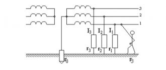
TN-C grounding system diagram. For a single-phase system, discard L1, L2.
What do we see in this diagram? First and most important. The neutral point of the generator or transformer is connected to ground (solidly grounded). Therefore, the neutral point of the transformer is at ground potential. And since a person also has earth potential, there is a zero potential difference between the body and the neutral conductor, and touching it is safe.
However, not all so simple. I repeat that due to phase imbalance, as well as a voltage drop on the PEN wire, a voltage other than zero may be present on it. Therefore, the PEN wire is forcibly “pulled” to ground potential at certain intervals along the line.
The Earth (what our planet is made of) is a universal and absolute zero in potential. But if a person is given the potential of a phase wire, then touching the ground will be fatal. At the same time, touching a wire with the same potential will be safe.
I saw a documentary about a man calmly descending from a helicopter onto a high-voltage line and working there.
In general, everything is relative. You can fall from a 5-story building to your death. Or you might not get hurt at all if you fall from the same building. From the first step of the first floor)
The TN-C system is currently officially prohibited and can only be used in three-phase systems where there is no phase imbalance and current does not flow through the PEN (zero, also protective) conductor in normal mode. As a result, there will be a zero potential on this wire (and therefore on the body of the device).
However, in old housing stock it is used everywhere because of its low cost. The low cost of the TN-C system is its only advantage. After all, the cross-section of the protective conductor PE in a single-phase network must be equal to the cross-section of the phase conductor. And this means an increase in the cost of all electrical wiring by at least a third.
Generally speaking, there is no grounding at all in this system, and I don’t quite understand why “this” is called a grounding system. Perhaps you can throw a zero on the body, and the device will be “sort of” grounded.
Even before, when all the wiring was done using this system, there were practically no household appliances that required grounding.
The first “swallows” were washing machines that beat with electric current. In the best case, they pulled a wire from the body of the access panel to them, in the worst case, they hooked the body of the car to a water pipe or to the neutral wire.
The desired effect, of course, is achieved, but the chances of falling under phase voltage increase significantly. The main danger comes from the fact that the neutral wire may break, and then all “zeroed” devices, and also devices with switching power supplies, will receive phase potential on their cases.
How to protect yourself from electric shock in the TN-C system? Here I remember the RCD (Residual Current Device). Let's imagine - a person touched a phase wire. The current bifurcates - part (hopefully, a larger part) goes into the neutral conductor, and part - through the human body to the body. There is a differential difference (sorry, tautology) in the currents in phase and zero, which should trigger the RCD.
However, the PUE directly states that in the TN-C system the use of RCDs is prohibited . Why?
The reason is that in this case, what I wrote about above can happen. An RCD is a switching device in which, for some reason, the PEN-conductor contact may be broken, and the entire consumer will come under phase voltage. Including the housings, if they are grounded, and this is how “grounding” is done in the TN-C system.
The PUE also says that the protective conductor (in this case, PEN) must not be broken under any circumstances , and must always be connected to the grounded device.
Therefore, RCDs can (and should!) be used in all systems except TN-C .
Here's a good picture to illustrate the situation:
RCD – application in various grounding systems
I scared you so much that the question will arise anyway: how to live with this now?
I answer. To avoid this “bad” system, the PEN conductor is divided into N and PE. Moreover, this must be done as far as possible from the consumer, and as close as possible to the voltage source.
Thus, we will switch to a much safer system - TN-CS , which I will talk about below.
In practice, the combined PEN conductor is grounded (re-grounded) at the entrance to the building, and there it is divided into neutral N and protective PE, which should not be connected ANYWHERE further.
Another option is the transition to a TT system , in which the protective conductor PE is made on the basis of the ground loop, and is not connected anywhere to the incoming PEN. In this case, PEN turns into N, since the protective current will never flow through it.
Grounding in an apartment with TN-C wiring
In apartments it is more difficult to separate zero and land. There are always heated debates among electricians about this.
I think there are two viable options here.
1. Leave the zero as is, and take the PE wire from the main PEN conductor. Let it not be from the conductor itself, but from the place where it is connected to the body of the floor panel. The main thing is that our N and PE are connected at different points. PE - on the body, N - on a bus isolated from the body, to which zero comes after the input switch or machine (if any) and the meter. By the way, this is what they did in Soviet times when connecting electric furnaces in apartments.
2. Conduct a three-wire system (L, N, PE), but do not connect PE anywhere. As a result, we do not make changes to the floor panel (by the way, this is prohibited!), but to all non-current-carrying parts of electrical appliances, metal structures, pipes, etc. we connect to this conductor. And within the apartment we have grace! Just an important note - groups of sockets must have RCDs in place in case of phase contact with the housing within the apartment.
That's it, now let's quickly go through other systems, everything is simpler there.
TN-S system
The third letter in the name is S. This means that the conductors N and PE are separated (Separated) along the entire length from the substation to the consumer.
Diagram and description of the TN-S grounding system
This grounding system is the safest and most preferred, but is used only in the newest electrical installations. Well, mostly in reality they now use the TN-CS system. That is, they are trying to bring the old system closer to the new one, moving the connection point N and PE away from the consumer and closer to the power source.
System TN-C-S
The last letters in the name mean that the N and PE conductors after the substation are connected (Connected) into one PEN wire, and then, at the entrance to the building, they are separated.
Scheme and description of the TN-CS grounding system
When a phase hits the housing, the short-circuit circuit breaker should trip. When touching live parts, the RCD should trip.
TT system
Terra – Terra. I already wrote in an article about this system, in which the PE grounding wire is connected to the grounding loop, and nowhere else. It is mainly used in private homes and temporary buildings and electrical installations.
Diagram and description of the TT grounding system
Everything is great if RCDs against touching live parts and circuit breakers against short circuits are also used.
But there is one minus. If in other systems it is not necessary to do your own grounding, relying on grounding at the substation or on poles, then in this case it will have to be done. And do it very well, so that in the event of a short circuit to ground, the short circuit current is sufficient to trigger the circuit breaker.
That is, it is possible that during a short circuit to the case the potential of the case will remain close to zero, everything is fine. But at the same time, the circuit breaker will not knock out, although a current close to the maximum will flow through it (and through the wiring of the house)! And the problem can creep up from the other side...
IT system
Finally, I’ll tell you about the specific IT grounding system. All other systems use power supplies (transformers) with a solidly grounded neutral. In other words, the neutral conductor on the source side is grounded.
However, in an IT system, the power source is completely isolated from the ground - both zero and (naturally)) phase.
As a result, there is no potential in relation to the ground. And if there is a short circuit to ground, nothing will happen, because the current will not flow, or will be negligible.
I have seen such systems for powering control circuits in serious industrial equipment. This system is also used in portable generators and other power sources, as well as in medical institutions. If one of the terminals of such a source is not grounded and connected to the load, it will operate according to the IT system.
I wrote more about this in an article about connecting a Hooter generator.
The downside of such a system is that if there is a ground fault, it will turn into a TN-CS with poor installation, and you may not even know about it if you don’t check it. And it will become dangerous.
Video on TN-C topic
Summarize. Grounding in the TN-C grounding system in everyday life is dangerous, and such modernization is unacceptable. If in an old apartment building you plan to switch from TN-C to TN-CS (which is unlikely), then privately, when replacing the electrical wiring, you can lay a three-wire cable with a phase, working N and protective PE conductor. But until the reconstruction is carried out, the PE protective conductor is not connected on both sides. That is, you lay it in the apartment. You insert one of its outputs into the socket boxes for installing sockets and switches, the second end is inserted into the shield. It is not connected on both sides, is isolated and left until the electrical supply system of the entire building is reconstructed.