In the process of moving charges inside a closed circuit, a certain amount of work is performed by the current source. It can be useful and complete. In the first case, the current source moves charges in the external circuit, while doing work, and in the second case, the charges move throughout the entire circuit. In this process, the efficiency of the current source, defined as the ratio of the external and total resistance of the circuit, is of great importance. If the internal resistance of the source and the external resistance of the load are equal, half of the total power will be lost in the source itself, and the other half will be released at the load. In this case, the efficiency will be 0.5 or 50%.
Electrical circuit efficiency
The efficiency factor under consideration is primarily associated with physical quantities characterizing the speed of conversion or transmission of electricity. Among them, power, measured in watts, comes first. There are several formulas to determine it: P = U x I = U2/R = I2 x R.
Electrical circuits may have different voltages and charge amounts, and accordingly, the work performed is also different in each case. Very often there is a need to estimate the speed at which electricity is transmitted or converted. This speed represents the electrical power corresponding to the work done in a certain unit of time. In the form of a formula, this parameter will look like this: P=A/∆t. Therefore, work is displayed as the product of power and time: A=P∙∆t. The unit of work used is the joule (J).
In order to determine how efficient a device, machine, electrical circuit or other similar system is in relation to power and operation, efficiency is used. This value is defined as the ratio of usefully expended energy to the total amount of energy entering the system. Efficiency is denoted by the symbol η, and is defined mathematically as the formula: η = A/Q x 100% = [J]/[J] x 100% = [%], in which A is the work performed by the consumer, Q is the energy given by the source . In accordance with the law of conservation of energy, the efficiency value is always equal to or below unity. This means that useful work cannot exceed the amount of energy expended in doing it.
In this way, the power losses in any system or device are determined, as well as the degree of their usefulness. For example, in conductors, power losses occur when electrical current is partially converted into thermal energy. The amount of these losses depends on the resistance of the conductor; they are not part of the useful work.
There is a difference expressed by the formula ∆Q=AQ, which clearly shows the power loss. Here the relationship between the increase in power losses and the resistance of the conductor is very clearly visible. The most striking example is an incandescent lamp, the efficiency of which does not exceed 15%. The remaining 85% of the power is converted into thermal, that is, infrared radiation.
Inhomogeneous section of the chain
Rice. 2.4. Inhomogeneous section of the chain
A non-uniform section of a circuit is a section where external and electrostatic forces act
. (2.7)
Voltage on a non-uniform section of circuit 1–2 is a physical quantity determined by the work of electrostatic and third-party forces to move a positive unit charge (Fig. 2.4)
. (2.8)
Homogeneous chain section
A homogeneous section of a circuit is a section on which no external forces act, therefore the voltage on it is equal to the potential difference in Fig. 2.5.
Rice. 2.5. Homogeneous chain section
We obtain Ohm's law for a homogeneous section of the chain:
. (2.9)
Thus, the voltage on a homogeneous section of conductor 1–2 is a physical quantity determined by the work of electrostatic forces to move a positive unit charge.
2.2. Current power
Let us consider a non-uniform section of a direct current circuit, to the ends of which a voltage U
(Fig. 2.4).
During time t,
a charge passes through each section of the conductor:
. (2.10)
This is equivalent to the fact that charge q
is transferred in time
t
from one end of the conductor to the other. In this case, the electrostatic field and the external force acting in this area perform work:
What is the efficiency of a current source
The considered efficiency of the entire electrical circuit allows us to better understand the physical essence of the efficiency of the current source, the formula of which also consists of various quantities.
In the process of moving electric charges along a closed electrical circuit, a certain amount of work is performed by the current source, which is distinguished as useful and complete. While performing useful work, the current source moves charges in the external circuit. When fully operational, charges, under the influence of a current source, move throughout the entire circuit.
They are displayed as formulas as follows:
- Useful work - Apolez = qU = IUt = I2Rt.
- Total work – Total = qε = Iεt = I2(R +r)t.
Based on this, we can derive formulas for the useful and total power of the current source:
- Net power – Puse = Apoles /t = IU = I2R.
- Total power – Pfull = Afull/t = Iε = I2(R + r).
As a result, the formula for the efficiency of the current source takes the following form:
- η = Apoles/Atoll = Puse/Ptot = U/ε = R/(R + r).
Maximum useful power is achieved at a certain value of external circuit resistance, depending on the characteristics of the current source and load. However, attention should be paid to the incompatibility of maximum net power and maximum efficiency.
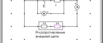
METHOD AND PROCEDURE OF MEASUREMENTS
Rice. 2.
Assemble the circuit shown in Fig. on the screen. 2. To do this, first click the left mouse button above the emf button. at the bottom of the screen. Move the mouse marker to the working part of the screen where the dots are located. Click the left mouse button in the working part of the screen where the emf source will be located.
Next, place a resistor in series with the source, representing its internal resistance (by first pressing the button at the bottom of the screen) and an ammeter (the button is in the same place). Then arrange the load resistors and voltmeter in the same way, measuring the voltage across the load.
Connect the connecting wires. To do this, click the wire button at the bottom of the screen, and then move the mouse marker to the working area of the circuit. Click with the left mouse button in the areas of the working area of the screen where the connecting wires should be located.
4. Set parameter values for each element. To do this, left-click on the arrow button. Then click on this element. Move the mouse marker to the slider of the regulator that appears, click on the left mouse button and, holding it down, change the parameter value and set the numerical value indicated in Table 1 for your option.
Table 1. Initial parameters of the electrical circuit
| Number option | 1 | 2 | 3 | 4 | 5 | 6 | 7 | 8 |
| E, B | 10,0 | 9,5 | 9,0 | 8,5 | 8,0 | 8,5 | 9,0 | 9,5 |
| r, Ohm | 4,8 | 5,7 | 6,6 | 7,5 | 6,4 | 7,3 | 8,2 | 9,1 |
5. Set the external circuit resistance to 2 Ohms, press the “Count” button and write down the readings of electrical measuring instruments in the corresponding lines of Table 2.
6. Use the regulator slider to consistently increase the resistance of the external circuit by 0.5 Ohms from 2 Ohms to 20 Ohms and, pressing the “Count” button, record the readings of electrical measuring instruments in Table 2.
7. Calculate using formulas (2), (7), (8), (9) P1, P2, Ptot and h for each pair of voltmeter and ammeter readings and write the calculated values in Table 2.
8. Construct on one sheet of graph paper the dependence graphs P1 = f(R), P2 = f(R), Ptot=f(R), h = f (R) and U = f(R).
9. Calculate the measurement errors and draw conclusions based on the results of the experiments.
Table 2. Results of measurements and calculations
| R, Ohm | 2,0 | 2,5 | 3,0 | 20 | |
| U, V | |||||
| I, A | |||||
| P1, W | |||||
| P2, VT | |||||
| Pfull, VT | |||||
| h |
What is a current source
This is a device or element, in the general sense, a two-terminal network in which the current passing through it does not depend on the voltage at the poles. Main characteristics of the current source (IT):
- size;
- internal conductivity (impedance).
The internal resistance of such a two-terminal network is very small. At an ideal source (IIT) it approaches zero.
Electron motion generators can be either independent or dependent.
The first are an ideal two-terminal network, with two terminals. In them, the current moving from one terminal to another does not depend on the shape and magnitude of the potential difference across the terminals. Its changes occur according to their own laws.
The second type of IT is an ideal two-terminal network, with two terminals, in which the movement of charges from one terminal to another depends on the shape and magnitude of the voltage at these terminals.
There is managed dependent IT. It is an ideal two-terminal network, having 2 input terminals and 2 output terminals. Its peculiarity is that the output current value at the output depends on its value at the input. In such IT there is an increase in power. By changing the zero power value at its input, the amount of power at the output terminals is controlled.
Information. The energy producer can be controlled by voltage (ITUN) or current (ITUT). Some are used for field-effect triodes and vacuum tubes, while others are used for bipolar transistors.
In reality, current generators have certain voltage limitations. They are far from ideal IT and create the movement of electricity in a voltage range where their upper limit depends on Upit IT. Therefore, a real current source has significant load limits.
Questions and tasks for self-control
- Write the Joule-Lenz law in integral and differential forms.
- What is short circuit current?
- What is gross power?
- How is efficiency calculated? current source?
- Prove that the greatest useful power is released when the external and internal resistances of the circuit are equal.
- Is it true that the power released in the internal part of the circuit is constant for a given source?
- A voltmeter was connected to the flashlight battery terminals, which showed 3.5 V.
- Then the voltmeter was disconnected and a lamp was connected in its place, on the base of which it was written: P = 30 W, U = 3.5 V. The lamp did not burn.
- Explain the phenomenon.
- When the battery is alternately shorted to resistances R1 and R2, an equal amount of heat is released in them at the same time. Determine the internal resistance of the battery.
Electrical circuit efficiency
By moving charges through a closed circuit, the two-terminal network does some work. When a generator moves charges along the outer circuit of a circuit, this is useful work. When IT moves electrical media throughout the chain, it is said to be fully operational.
Attention! In this chain of charge movement, the efficiency (efficiency factor) of the source is of particular importance. It is equal to the ratio of the external circuit resistance and the total resistance of the circuit.
Paying attention to the efficiency of an electrical circuit, it should be noted that it directly depends on the physical quantities that determine the speed of transmission or transformation of electrical energy. One of these quantities is power P (W).
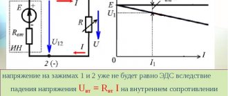
Ohm's law for a complete circuit
In a previous article, I talked about Ohm's law, which establishes the relationship between voltage and current flowing through a section of a circuit. However, when trying to apply it to the entire circuit, which contains, in addition to resistance, a voltage source, it leads to incorrect results, since a real voltage source, as we know, has some internal resistance.
Ohm's law for a complete circuit.
Therefore, the total resistance of the circuit is the sum of the internal resistance of the energy source RВН (usually small) and the external resistance of the load RН (almost always much larger than RВН), therefore for a complete circuit Ohm's law will have the following form
After analyzing this expression, we can come to the following practical conclusions:
- When connected to a load power source, the voltage of the power source is less than its EMF, since a certain voltage UВН drops across the internal resistance RВН of the power source
Therefore, when the load is disconnected, the voltage of the power source will be equal to the EMF. This application is used to measure the EMF of power supplies.
- The voltage of the power source changes when different loads are connected, and the lower the value of the load resistance, the lower the voltage of the power source, since different values of load resistance cause different current in the circuit, and therefore the voltage drop across the internal resistance of the source changes
- In some cases, it becomes necessary to measure the internal resistance of the energy source. This can be done using the following diagram
Circuit for measuring energy source.
First, the EMF of the power source E is measured by opening the switch S1, then closing the switch S1 and measuring the current I flowing through the circuit and the voltage of the power source under load UH. Thus, the voltage drop across the internal resistance of the power supply UВН is calculated. Then, the value of the internal resistance RВН will be calculated as the ratio of the internal voltage drop to the current flowing in the circuit
For example, with switch S1 open, the voltage at the output of the power source was U = E = 1.5 V. When switch S1 was closed, the current was I = 0.18 A, and the voltage was UH = 1.42 V. Then the internal resistance RВН of the power source will be
What is IT efficiency
When we talk about the efficiency of a current source, we also consider the useful and total work done by the two-terminal network. By moving electrons in the external circuit, it performs useful work; by moving them throughout the entire circuit, including its internal circuit, it produces complete work.
In formula form it looks like this:
- And useful. = q*U = I*U*t = I2*R*t;
- A full = q*ε = I* ε*t = I2*(R+r)*t.
Where:
- q – amount of energy, J;
- U – voltage, V;
- ε – emf, V;
- I – current, A;
- R – load resistance, Ohm;
- r – source impedance, Ohm;
- t is the time during which the work is done, s.
Taking this into account, we can express the power of a two-terminal network:
- R useful. = A useful/t = I*U = I2*R;
- P full = A total/t = I*ε = I2*(R+r).
The formula for the efficiency of current sources is:
η = P useful/P total= U/ε = R/ R+r.
Study of power and efficiency of current generator
Maximum useful Pmax and maximum efficiencymax are incompatible concepts. Maximum source efficiency cannot be achieved at maximum power. This is due to the fact that P, given by a two-terminal network, will reach its maximum value only if the load resistance and the internal impedance of the IT are matched:
In this case, the source efficiency will be:
η = R/ R+r = r/ r+r = 1/2, which is only 50%.
To match the two-terminal network and the load, electronic circuits or matching blocks are used in order to achieve maximum power take-off from the source.