When installing a new or upgrading an old panel with a new circuit breaker, it is necessary to install a residual current device. The device protects the line from overloads, short circuits and prevents household appliances from breaking down. Some craftsmen cannot decide whether to install an RCD before or after the machine. Popular diagrams will help you choose the connection method.
Operating principle of RCD, differences from difavtomat
The requirements of the PUE indicate the need to install protective equipment. It provides protection against electric shock and breakdowns of the cable insulation coating. The RCD can be connected to 2 wires in a network with a voltage of 220 V and to 4 wires in a network of 380 V.
The disadvantage of the device is the inability to detect overload or short circuit. An automatic switch will further protect it. The difference between the devices is the response of the RCD to the current imbalance of phase and zero with a nominal value of 10-30 mA. The device does not recognize overcurrents and may even catch fire under their influence.
The difavtomat operates normally at a current of up to 16 A, and turns off the line in case of leaks. Unlike an RCD, it has a time-current characteristic, which determines the speed of shutdown.
A switch with an electromagnetic release trips when the current value exceeds 5-10 times.
Features of integrated operation of protective devices
To understand how to install an RCD - after or before the machine, you need to understand the functionality of the installation. A good example would be a system consisting of a metering device, a residual current device, or a circuit breaker connected to one line.
The voltage from the transformer will pass through the RCD and the meter, supplied to the sockets. If there is no protection, the shutdown device burns out. The absence of a release in front of the meter will also lead to a line fire. The best option is a protective device on both sides.
According to the requirements of the PUE, two-pole modifications of machines are placed before the metering device. There is no need to place it in front of it - it is better to protect the line from the RCD to the consumers.
Installing an RCD before or after the machine
The device responsible for disconnecting the line does not respond to overcurrents, therefore it does not operate in the event of short circuits and overloads. A joint connection with a difavtomat will prevent these situations.
Since the circuit current exceeds the rated current, the internal components of the device are damaged and the contacts burn out. Models without built-in protective elements must be installed together with circuit breakers that will eliminate the effects of overloads and short circuits. In this case, the current of the circuit breaker should not exceed the current rating of the RCD. For example, the latter reacts to 40 A. The optimal switch for it is 36 A.
Connection diagrams for RCD with switch
Protective equipment must be connected using two cables. The first will carry the load current, the second will be directed to the external circuit from the consumers. In order not to think about installing an RCD before or after the machine, you should use popular schemes.
For several groups of difavtomats - one RCD
Clause 7.1.79 of the PUE allows for the protection of several lines using an RCD. The device needs to be placed on top, then the switches on the consumer groups. In case of short circuits, the current passes through the RCD to the group circuit breaker, then to the power cable and to the consumer. If the rating of the devices is selected correctly, none of them will be damaged.
The advantages of implementing the scheme include saving money and space in the distribution panel. The downside of the connection is that all groups are disconnected after the RCD is triggered.
Installation of RCD to the machine
The diagram provides for installation in the following sequence:
- Safety shutdown device.
- Difavtomat.
- Power cord.
- Consumer.
If there is damage, the short circuit current passes through the RCD until the circuit breaker stops.
RCD after the machine
The system is assembled according to the principle;
- switch - two-pole or feeder;
- counter;
- RCD;
- machines depending on the number of lines.
This option is correct, since it is easy to understand how to turn off the machine and apply input to its terminals. Despite the fact that RCDs break more often, they are easier to replace.
At the moment of a short circuit, the current will pass from the switch to the RCD, then to the power wire, then to the consumer. The switch stops and the protective device remains intact.
To prevent overload, a second automatic circuit breaker can be installed between the meter and the RCD.
Connecting an RCD to a group of machines
A similar circuit is assembled in a three-phase switchboard, where there are:
- 3 three-phase difavtomat;
- three-phase RCD;
- 2 single-phase RCDs;
- 4 single-phase single-pole circuit breakers.
From the first input circuit breaker, the voltage will go to the second three-phase circuit through the upper terminals. From the same device, one phase will go to a single-phase RCD, the second to the next one.
Single-phase protection devices have two poles, difautomatic devices have one. In order for the system to work without failures, it is necessary not to connect the working zero after it. For this reason, a zero bus must be installed after each protective device.
If there are two-pole circuit breakers, a separate zero bus is not installed. When two zeros are combined, a false positive may occur.
The first single-pole RCD is connected to differential circuit breakers No. 1 and No. 3, the second - to No. 2 and No. 4. The load is applied to the lower terminals.
The grounding bus is common, but it must be installed separately. Three phases with a working zero are connected to the input device. It is connected to the common zero, and then diverted to all RCDs. After device No. 1 it goes to a three-phase load, after the remaining single-phase loads - to each bus.
The wire into PEN and PE is not separated - ground, zero and 3 phases go to the shield.
Where should the RCD be installed?
To determine where to install the residual current device, you need to remember the speed of current flow through the wires. It is equal to the speed of light - 300 thousand km/sec. In a standard C 16 machine, the turn-on time when passing currents of 5×In (80 A) will be 0.02 seconds. The distance it will cover is 6000 km.
In the event of a short circuit, the current will completely pass through the coupling device - RCD - cable - socket. In this case, the switch does not operate instantly, as a result of which the insulation melts and the socket contacts burn out.
The RCD does not fail, since a short circuit is an inertial reaction. A time of 0.02 seconds is simply not enough to melt the insulating coating and damage the parts. Even taking into account the breaking capacity, the protective devices will work properly regardless of the installation location:
- Automatic - RCD. The phase is supplied using a jumper, and the zero is supplied directly to the protective device. The wire for the sockets is connected to the device and the PE bus.
- RCD - automatic. The wire is connected to the sockets through different paths. The phase one goes to the machine, the zero goes to the protection device or the zero bus.
Thus, there is no difference where the RCD was installed - before or after the automatic device.
Machine denomination
On the body of any device the nominal value is indicated - the value of the maximum continuous current that passes through the device without harm. This parameter is safe for current switching.
To ensure protection of the RCD itself, it is necessary to install a circuit breaker with a rating similar to or 1 more than the rating of the device. If you have a machine with a rating of 16 A, the RCD should be about 25 A. This current reserve will be enough to prevent the flow of energy when the load increases.
The machine is triggered when a current appears 13% higher than the nominal value: a 16 A modification will operate at a current of 18 A. If the RCD rating is equal, the contacts may heat up. To select the rating of a system with several circuit breakers, you need to sum them up and select an RCD with a larger rating.
The nuances of installing a protective device
Connecting an RCD in an apartment or house requires compliance with several rules:
- For several groups of consumers it is necessary to install one RCD and individual circuit breakers.
- If there are several RCDs, each of them will need a zero output bus.
- The TN-C system does not need to be zeroed.
- For “wet groups” it is mandatory to install a protective device with a shutdown rating of 10 mA.
- 30 mA devices are suitable for household appliance outlets that operate with water.
- The zero terminal is located on the right side of the device and is marked with the letter N. It should not be confused with the phase (index L).
- Input can be made to the lower or upper terminals.
- The classic circuit is implemented using a top input and a bottom output.
- Each RCD requires a personal zero block to which all working neutrals are connected.
- For lines with ripple currents, type A devices are required.
You can check the health of the system by pressing the “Test” button.
A protective shutdown device is needed to protect against overloads and short circuits. Due to the lack of response to overcurrents, it is installed in combination with a difavtomat. Connection diagrams allow installation of devices in any order. The only condition is the choice of the appropriate denomination.
How to properly connect machines and RCDs
Before starting work on connecting the machines, it is necessary to prepare all the devices:
- Mounting rail (sometimes it is already included with the finished shield). In other cases, you will need to measure the required length yourself and cut it with metal scissors.
- Screwdriver.
- Wire cutters.
- Wire stripper.
Connecting machines and RCDs - step-by-step instructions
Step 1. To begin, you should attach two buses to a metal DIN rail: neutral and ground. This is easy to do; you just need to insert them at one end and then snap them into place.
This is what the tires should look like after installation.
Step 2. Now you need to secure the machines in series. At the bottom they have a special latch, which you just need to pull down and then secure the machine to the rail.
Each machine must be secured to the rail one by one.
Step 3. Next you need to take a three-core cable. As a rule, the ground wire is yellow, the neutral is blue, and the phase is white or pink (as in our case).
It is important not to mix up the power cable wires
Step 4. First we need to connect the neutral wire to the neutral bus. This is easy to do - you just need to unscrew the bolt with a screwdriver.
There is a hole for cables of different sections
Step 5. Now you need to connect the yellow ground wire to the ground bus.
This is done in the same way as in the previous version.
Step 6. The next step is to secure the power wire (pink). Contrary to many opinions, it should always come from the top. You should connect the wire, but you shouldn’t tighten it right away - the reason is that you will then have to supply the power wire to all other machines.
In this step, the wiring is connected “live”
Step 7. Seventh: you need to insert the power wire into the upper machine, and then insert one end of the additional jumper into the same hole.
Now you need to insert the jumper into the adjacent machine, and then into the other, alternately tightening the screws
Step 8
Now you need to pay attention to the last differential machine. On its body, as a rule, there is a connection diagram. The first input here will be designated by the letter N - this will be zero, the second input will be designated as I (L) - this will be the phase
The first input here will be designated by the letter N - this will be zero, the second input will be designated as I (L) - this will be the phase.
Step 9. Now it has become clear that the phase is at the second input, which means that the other end of the yellow jumper wire should be secured there. We tighten the screw by analogy with the previous options.
Thus, we have completed connecting the power cable that comes from the shield
Step 10. Now you need to connect the wires that come from the room. First, you will need to remove the insulation layer from their ends. A special tool is used to strip the ends of the wires.
Here you can turn the screw and set the wire thickness
Step 11. Here you should also connect the neutral wire to the corresponding bus.
You can unscrew any loose bolt
Step 12: Now you need to secure the ground wire again.
The wire must be tightened carefully, without catching the insulation layer.
Step 13. Now from below we fix the power wire that comes from the electrical device.
The following wiring, by the same analogy, will be connected only from below
Step 14. Now you need to take an additional wire, connect it to the zero bus, and then to the first input on the differential machine.
We fix the wire in the first hole of the difavtomat
Connection errors: how to avoid them
The question is often asked: how to connect an RCD correctly so that the circuit works without failures? As an answer, the following are the most typical miscalculations when connecting protective equipment without grounding.
- Interweaving of neutral conductors coming out of the device into a single unit. This provokes unreasonable alarms and makes it difficult to check the correct installation. To make sure that the assembly procedure without grounding is followed, plug the electrical appliance into the socket connected to the RCD. If it works, the circuit is assembled correctly.
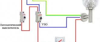
- Connecting the grounding wires of sockets to the neutral wire of the RCD or to a homemade grounding circuit. This violates electrical safety standards: an amateur circuit often causes a short circuit. When connecting the grounding switches of the sockets to water supply or heating pipes, an electric shock can strike not only the people living in the apartment, but also their neighbors.
- Neutral and ground connection. In this case, the RCD simply will not operate, since it works due to the difference in current strength in the phase and neutral wires. The connection between zero and ground provokes stable power outages in the apartment. If the grounding circuit does not work, then the grounding wires from the devices coming to the electrical panel should be wrapped with insulating tape: otherwise, the conductive parts of the household appliances may be exposed to dangerous voltage.
How to properly connect an RCD. demonstrates a video clip that details the sequence of all operations - thanks to the visual lesson, even a non-professional can easily cope with installing single-level protection. If the circuit is more complex, requires the coordinated operation of several protective devices, and is associated with a grounding connection, it is better to order installation by a professional electrician - so as not to be constantly without power and to operate electrical appliances safely.
Purpose and operating principle of RCD
First of all, let's consider why this device is needed and for what purpose it is placed in the mains supply line. An unprofessional approach to these issues gives the impression that one circuit breaker is sufficient to reliably protect power lines. But ouzo is required in order to protect humans and animals from electric shock in the presence of its leaks.
A feature of devices of this class is their high sensitivity to very small currents, amounting to fractions of an ampere and always present in places of high humidity or damaged insulation. That is why installing an ouzo is the most reliable way to protect living organisms (including pets) from possible electric shock in a number of hazardous areas, found not only in city apartments, but also in private residential buildings.
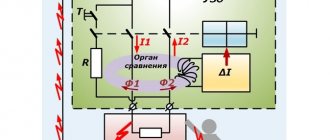
The operation of an RCD is based on the principle of comparing currents in a special differential unit with a direct and reverse tap from a single-phase line inserted into it (its inclusion in the supply circuit is shown in the figure below).
Let us consider the essence of the functioning of this device in more detail in the form of the following sequence of its states:
- In normal (standard) operating mode, forward and reverse currents flowing through the differential unit have the same amplitude values. In this case, the protective devices do not react in any way to changes in currents in the line, since the magnetic fields created by the inductive coils are mutually compensated (the currents through them are equal in magnitude);
- If there is a leak through a living organism (its value is measured in microamperes), a current difference appears in the differential or comparing unit, disturbing the balance of magnetic fluxes F1 and F2;
- The consequence of this is the formation of a control pulse supplied to the executive relay, which disconnects the line from the consumer (load).
Note! The speed of such shutdowns or actuation of the executive relay is usually calculated in fractions of seconds (more precisely, microseconds). In such a short time, current processes do not have time to spread throughout the body of a living organism, which means one hundred percent protection from electric shock
In such a short time, current processes do not have time to spread throughout the body of a living organism, which means one hundred percent protection from electric shock.
Connection in an apartment and in a private house
For a washing machine,
the connection diagram in the apartment is carried out only via a single-phase network. For this reason, the connection is made in the following order:
Connection in the apartment
If you have power consumers of electricity in your apartment, for example, a washing machine or an electric oven, then it is recommended to additionally connect an RCD protective device.
As for connecting the machine in a private house, the connection sequence is as follows:
- Introductory machine.
- Electricity meter.
- Automatic from 100 to 300 mA, the choice is made depending on the amount of current consumed by all household appliances.
- Automatic machine for individual current consumption. Typically, 10 to 30 mA is used.
So, we have examined with you some of the features and differences of connecting an RCD in certain circumstances. Most importantly, remember that if you have no idea at all about this system, then it is better not to experiment.
A few words about typical errors when connecting an RCD:
To correctly install the RCD, we suggest that you familiarize yourself with some of its connection diagrams:
Residual current device
Connecting an RCD with automation
Connection to 380V network
Four-pole RCD without zero
Apartment group panel
1. Connecting a four-pole RCD to a three-phase network using a neutral. Your diagram shows a single-phase network. Above the green wire the inscription is blue. This wire should be yellow-green. 2. Connecting a four-pole RCD in a single-phase network. The figure shows a two-pole (single-phase) RCD.
Alexander! Thank you very much for your relevant comments. These shortcomings will be eliminated in the near future. We apologize for any inaccuracies in the illustrations posted.
- How to connect a washing machine with your own hands
- Instructions for replacing heating elements in a washing machine
- How to make an electric heated floor
- Operating principle of the air conditioner
Video about installing electrical wiring yourself
Explanation of the designations of the F200 series ABB
In the designation of the RCD series 200 manufactured by ABB, each number and letter corresponds to a specific parameter:
- F2 - series;
- F - standard, FH - economical, without connecting additional devices, FAP-R - with the prevention of false alarms, S - selective, AE - with the possibility of emergency shutdown;
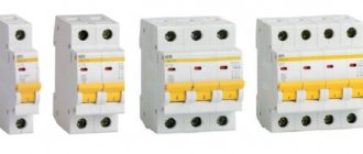
- 202 - two-pole (single-phase), 204 - four-pole (three phases and zero);
- A - alternating and pulsating current, AC - only alternating current;
- rated current - 16,25,4,,63,80,100;
- operation current (leakage) - 1 - 0.01A, 2 - 0.03A, 3-0.1A, 4-0.3A.
For example, decoding the name of the differential relay (RCD) ABB FH202 AC-63/0.03:
- F200 series;
- bipolar (single-phase);
- economical design (without connecting additional devices);
- alternating current;
- rated current - 63A;
- operation current (leakage current) - 0.03A.
Two-phase electrical network: how to connect an RCD
First, it’s worth understanding why it is necessary to install protection in two-phase circuits. These are primarily observed in apartments located in old buildings, and in such conditions, additional safety is necessary, since more often in such housing there is no grounding, and current leakage in places where it should not exist often leads to a fire.
Let's talk about a single-level security system
The connection option is too simple at first glance, however, taking into account the nuances is important for complete safety
- The most powerful device is selected;
- The installation must provide for the transfer of current to the machine, and from it to all devices, including light bulbs and sockets;
- The design of this circuit is compact and elementary.
It is customary to install single-level protective devices on one device, too, for example, for a washing machine or water heater. To implement this method, a device with a power of 15 amperes is sufficient.
Scheme for connecting RCDs and automatic machines to the electricity meter
Let's turn to the question, like a machine gun, while implementing multi-level protection.
If a protected shutdown device is installed for individual areas, then we will talk about multi-level protection of a house or apartment. Typically, this diagram is for homes where grounding is present. In terms of price category, this option exceeds previous marks, and the devices are large in size. However, this system has such a significant advantage as the presence of autonomy for each individual household appliance. In the event of a short circuit in one of the devices, the entire living area will not be de-energized, but only the one in which there is a current leak from the network will cease to function. Here the connection to the electrical network changes; now there are as many cables coming out of the reading device as there are protection devices.
Today, RCDs and differential relays are often used, the connection diagram of which differs in that there is an absence of an automatic device. The general principle of connecting a system with a differential device is similar to the previous one, but the installation of additional current protection is provided.
How to choose: what the labeling tells you
Before learning how to calculate the performance of fire fighting equipment, it is important to choose the right device with ideal technical characteristics. They will be indicated by markings on the body
The device must contain the following information:
- manufacturer, brand;
- series or product number;
- voltage in nominal designation;
- operating frequency;
- operating current;
- indicator at which the device will operate;
- the highest values for turning on and off;
- protection;
- the position in which the device should be located;
- installation diagram;
- performance indicators for normal functioning.
These are the main indicators that any high-quality equipment must have, be it a fire protection RCD or for a water heater.
The device must have a passport indicating the license, certification, verification and its compliance with state quality standards. The use of units that do not have such documents is strictly not recommended for safety reasons.
The RCD passport must contain complete information about the unit
Connection diagrams for RCD with switch
Protective equipment must be connected using two cables. The first will carry the load current, the second will be directed to the external circuit from the consumers. In order not to think about installing an RCD before or after the machine, you should use popular schemes.
For several groups of difavtomats - one RCD
Clause 7.1.79 of the PUE allows for the protection of several lines using an RCD. The device needs to be placed on top, then the switches on the consumer groups. In case of short circuits, the current passes through the RCD to the group circuit breaker, then to the power cable and to the consumer. If the rating of the devices is selected correctly, none of them will be damaged.
The advantages of implementing the scheme include saving money and space in the distribution panel. The downside of the connection is that all groups are disconnected after the RCD is triggered.
Installation of RCD to the machine
RCD in front of the machine
The diagram provides for installation in the following sequence:
- Safety shutdown device.
- Difavtomat.
- Power cord.
- Consumer.
If there is damage, the short circuit current passes through the RCD until the circuit breaker stops.
RCD after the machine
RCD after the machine
The system is assembled according to the principle;
- switch - two-pole or feeder;
- counter;
- RCD;
- machines depending on the number of lines.
This option is correct, since it is easy to understand how to turn off the machine and apply input to its terminals. Despite the fact that RCDs break more often, they are easier to replace.
At the moment of a short circuit, the current will pass from the switch to the RCD, then to the power wire, then to the consumer. The switch stops and the protective device remains intact.
Connecting an RCD to a group of machines
Connecting an RCD to a group of machines
A similar circuit is assembled in a three-phase switchboard, where there are:
- 3 three-phase difavtomat;
- three-phase RCD;
- 2 single-phase RCDs;
- 4 single-phase single-pole circuit breakers.
From the first input circuit breaker, the voltage will go to the second three-phase circuit through the upper terminals. From the same device, one phase will go to a single-phase RCD, the second to the next one.
Single-phase protection devices have two poles, difautomatic devices have one. In order for the system to work without failures, it is necessary not to connect the working zero after it. For this reason, a zero bus must be installed after each protective device.
If there are two-pole circuit breakers, a separate zero bus is not installed. When two zeros are combined, a false positive may occur.
The first single-pole RCD is connected to differential circuit breakers No. 1 and No. 3, the second - to No. 2 and No. 4. The load is applied to the lower terminals.
The grounding bus is common, but it must be installed separately. Three phases with a working zero are connected to the input device. It is connected to the common zero, and then diverted to all RCDs. After device No. 1 it goes to a three-phase load, after the remaining single-phase loads - to each bus.
The nuances of installing a protective device
Connecting an RCD and a breaker in a single-phase TN-C system
Connecting an RCD in an apartment or house requires compliance with several rules:
- For several groups of consumers it is necessary to install one RCD and individual circuit breakers.
- If there are several RCDs, each of them will need a zero output bus.
- The TN-C system does not need to be zeroed.
- For “wet groups” it is mandatory to install a protective device with a shutdown rating of 10 mA.
- 30 mA devices are suitable for household appliance outlets that operate with water.
- The zero terminal is located on the right side of the device and is marked with the letter N. It should not be confused with the phase (index L).
- Input can be made to the lower or upper terminals.
- The classic circuit is implemented using a top input and a bottom output.
- Each RCD requires a personal zero block to which all working neutrals are connected.
- For lines with ripple currents, type A devices are required.
You can check the health of the system by pressing the “Test” button.
A protective shutdown device is needed to protect against overloads and short circuits. Due to the lack of response to overcurrents, it is installed in combination with a difavtomat. Connection diagrams allow installation of devices in any order. The only condition is the choice of the appropriate denomination.
In the apartment
Let's look at the case when the installation of protection equipment takes place in an apartment panel. Some builders, when delivering houses with an open plan, rent out housing without wiring the internal electrical network. This is understandable; it is not known where the partitions and, accordingly, sockets and lighting will be located. Therefore, they only introduce cable into the apartment.
On the floor electrical panel there is an introductory circuit breaker and an electric meter. The future owner enters into a contract with another contractor for internal electrical work. The wiring diagram will vary depending on customer requirements. It will depend on the circuit and the loads which RCD to install. If desired, any man can do this work on his own.
We will assume that the wiring in the apartment corresponds to the protection installation diagram presented in the previous figure. The input machine and counter are located in the floor panel, and all other elements will be located in the apartment box. To do this, you need to install an electrical panel in the corridor, next to the cable entry point. The sequence of work during installation is as follows:
- the input machine is turned off. A sign “Do not turn on, people are working” is posted;
- An outlet is connected to the cable that was brought into the apartment. It will be needed to connect working tools and lighting;
- the plate is removed, the machine is turned on;
- holes are drilled in the wall using a hammer drill for fastening the box. Dowels are inserted and the shield is attached to the wall with screws;
- after this, a metal strip is inserted and secured to the inner wall of the box with screws.
There shouldn’t be any difficulties if you perform all the steps consistently and carefully.
Connection recommendations
Before connecting the ouzo to the power supply line along with distribution (linear) machines, the user should be reminded of a number of requirements for devices of this class by current regulations.
In general, they come down to instructions according to which the sequence and order of actions when installing an RCD are established
When considering these requirements, it is recommended to pay special attention to the following important points:
- In private houses with power equipment connected to a 380 Volt network, the installation of a three-phase protection device is required;
- To connect a three-phase ouzo, wires of the appropriate cross-section in insulation of different colors must be used;
Note! The color of insulating coatings is selected according to generally accepted standards. A visual representation of the choice of wire colors can be obtained in the figure below;
A visual representation of the choice of wire colors can be obtained in the figure below;
Wire colors by phase
To design the common (ground) terminal of a three-phase circuit, as a rule, a wire in blue insulation is used.
Taking into account all the above conditions, the connection procedure in this case can be represented by a list of recommendations and advice coming from specialists. Below are just a few of them:
- Protective devices are placed in their designated places only after the power line of the apartment or house is completely de-energized;
- Before connecting ouzo and automatic machines into a single electrical circuit, try to decide on the place intended for their installation on the instrument panel;
- It is recommended to choose it as close as possible to the electric meter installed on the input panel;
- The so-called “individual” RCDs, designed to protect a single supply line (bathroom, for example), must be used strictly for their intended purpose. They are not allowed to be installed after the meter as a general protective device for the apartment.
In the final part of the review, which covers the questions: why is an RCD needed, and how should it be connected to already installed equipment, we note the following.
When answering the question whether ouzo should be placed immediately after the counter, there is always a consonant statement. In this article you can also find out which ouzo to choose if the apartment has a given number of machines. We hope that after reading all the material presented, users will be able to independently understand the issues of installing protective devices in power circuits.
Selection of RCD by parameters
After the RCD connection diagram is ready, it is necessary to determine the parameters of the RCD. As you know, it will not save the network from overloads. And from a short circuit too. These parameters are monitored by the circuit breaker. To ensure the safety of all wiring, an input machine is installed at the entrance. After it there is a meter, and then they usually install a fire protection RCD. It is chosen specifically. The leakage current is 100 mA or 300 mA, and the rating is the same as that of the input circuit breaker or one step higher. That is, if the input circuit breaker is set at 50 A, the RCD after the meter is installed at either 50 A or 63 A.
The fire protection RCD is selected according to the rating of the input circuit breaker
Why a step higher? Because automatic protective switches operate with a delay. They can carry a current that exceeds the rated current by no more than 25% for at least an hour. The RCD is not designed for prolonged exposure to high currents, and is likely to burn out. The house will be left without electricity. But this applies to determining the rating of a fire protection RCD. Others are chosen differently.
Rated current
How to choose the RCD rating? It is selected according to the method for determining the rating of the machine - depending on the cross-section of the wire on which the device is installed. The rated current of the protective device cannot be greater than the maximum permissible current for a given wire. To make selection easier, there are special tables, one of them is below.
Table for selecting the rating of the circuit breaker and RCD
In the leftmost column we find the wire cross-section; to the right there is the recommended rating of the circuit breaker. The RCD should have the same. So choosing the rating of the leakage current protective device is not difficult.
Trip current value
When determining this parameter, you will also need an RCD connection diagram. The rated breaking current of the RCD is the value of the leakage current at which the power is turned off on the protected line. This parameter can be 6mA, 10mA, 30mA, 100mA, 500mA. The lowest current - 6 mA - is used in the USA, in European countries, and we don’t even have them for sale. Devices with a maximum leakage current of 100 mA or higher are used as fire protection. They are standing in front of the entrance machine.
For all other RCDs, this parameter is selected according to simple rules:
- Protection devices with a rated shutdown current of 10 mA are installed on lines that go into rooms with high humidity. In a house or apartment, this is the bathroom; there may also be lighting or sockets in the bathhouse, swimming pool, etc. The same shutdown current is set if the line powers one electrical appliance. For example, a washing machine, electric stove, etc. But if there are sockets on the same line, more leakage current is needed.
- An RCD with a leakage current of 30 mA is placed on group power lines. When more than one device is connected.
This is a simple algorithm based on experience. There is another method that takes into account not only the number of consumers, but also the rated current in the protection zone, or rather, the cross-section of the wire, since the rated current of the power supply line depends on this parameter. This is more correct, since it explains how to select the value of the leakage current for a general RCD, for example, and not just for devices that are installed on consumers.
Table for selecting the rated shutdown current for RCDs
It is also necessary to take into account the individual leakage currents of each device. The fact is that on every more or less complex device some small current “leaks away”. Responsible manufacturers indicate it in the specifications. Let’s say there is only one device on the line, but its own leakage current is more than 10 mA, install an RCD with a leakage current of 30 mA.
Monitored leakage current type and selectivity
Different instruments and devices use current of different forms, accordingly, the RCD must control leakage currents of different types.
- AC — alternating current (sinusoidal shape) is monitored;
- A - variable + pulsating (pulses);
- B - constant, pulsed, smoothed variable, variable;
- Selectivity. S and G - with a shutdown time delay (to exclude accidental operations), the G-type has a shorter shutter speed.
Selecting the type of leakage current to be monitored
The RCD is selected depending on the type of load being protected. If digital equipment is connected to the line, either type A is required. The lighting on the line is AC. Type B is, of course, good, but too expensive. It is usually installed in areas with increased danger in production, and very rarely in the private sector or in apartments.
RCDs of class G and S are installed in complex circuits if there are RCDs of several levels. This class is chosen for the “highest” level, then when one of the “lower” ones is triggered, the input protective device will not turn off the power.
FAQ
Experienced electricians are often asked by home craftsmen to explain certain points. Among the most common questions:
- Where to put it? It’s more convenient and functional – in electrical panels. Make sure there is no unsymmetrical load.
- Can it be installed on an alarm or fire system? The answer is no. Disabling systems can negatively affect the safety, health and even life of a person, therefore, such systems are not disabled.
- How to choose by power? The simplest option is based on the number of household appliances that operate in the room.
- Which RCD to choose: electrical or electromechanical? The former are more expensive and are not practical to use in everyday life. The latter work without external power.
- Do I need an adapter with protection? Of course, when it is used in wooden houses and dachas.
- Why do you need an RCD if there are automatic machines? The first one is cheaper, it is much easier to install and operate than automatic machines. Works for a long time, without problems.
Connection diagrams for RCDs in a single-phase network
Most household consumers are powered by a single-phase circuit, where one phase and neutral conductor is used to supply them with electricity.
Depending on the individual characteristics of the network, single-phase power supply can be provided according to the following scheme:
- with a solidly grounded neutral (TT), in which the fourth wire acts as a return line and is additionally grounded;
- with combined neutral and protective conductor (TN-C);
- with separated zero and protective grounding (TN-S or TN-CS; when connecting devices indoors, you will not find any difference between these systems).
It should be noted that in the TN-C system, in accordance with the requirements of clause 1.7.80 of the PUE, the use of differential circuit breakers is not allowed, except for the protection of individual devices with the obligatory combination of zero and ground from the device to the RCD. In any situation, when connecting an RCD, the characteristics of the supply network should be taken into account.
Without grounding
Since not all consumers can boast of having a third wire in their wiring, residents of such premises have to make do with what they have. The simplest circuit for connecting an RCD is to install a protective element after the input circuit breaker and the electric meter. After the RCD, it is important to connect circuit breakers for different loads with the corresponding shutdown current. Please note that the operating principle of RCDs does not provide for disconnecting current overloads and short circuits, so they must be installed together with circuit breakers.
Rice. 1: Connecting an RCD in a single-phase two-wire system
This option is relevant for apartments with a small number of connected devices. Since if there is a short circuit in any of them, shutting down will not bring any noticeable inconvenience, and finding the damage will not take much time.
But, in cases where a sufficiently branched power supply circuit is used, several RCDs with different operating current values can be used.
Rice. 2: connecting an RCD in a branched single-phase two-wire system
In this connection option, several protective elements are installed, which are selected according to the rated current and operation current. As general protection, an incoming 300 mA fire protection RCD is connected here, followed by a neutral and phase cable to the next 30 mA device, one for sockets, and the second for lighting; a pair of 10 mA units are installed for the bathroom and nursery. The lower the response rating is used, the more sensitive the protection will be - such RCDs will operate at a significantly lower leakage current, which is especially important for two-wire circuits. However, it is also not worth installing sensitive automation on all elements, since it has a high percentage of false positives.
With grounding
If there is a grounding conductor in a single-phase system, the use of an RCD is more appropriate. In such a scheme, connecting the protective wire to the device body creates a path for current leakage if the insulation of the wires is broken. Therefore, the protection will operate immediately in the event of damage, and not in the event of electric shock to a person.
Rice. 3: Connecting an RCD in a single-phase three-wire system
Look at the figure; the connection in a three-wire system is made in the same way as a two-wire system, since only a neutral and phase conductor are required for the device to operate. The grounding device is connected only to the protected objects through a separate grounding bus. Zero can also be connected to a common zero bus; from the zero contacts it is routed by wires to the corresponding devices connected to the network.
As in a two-wire single-phase circuit, with a large number of consumers (air conditioner, washing machine, computer, refrigerator and other amenities of civilization), an extremely unpleasant option is the freezing of all of the above electronic circuits with loss of data or disruption of their functionality. Therefore, several RCDs can be installed for individual devices or entire groups. Of course, connecting them will result in additional costs, but will make finding damage a more convenient procedure.
I am a home electrician myself – popular about electrical engineering
RCD (residual current device)
is an installation electrical product designed to cut off the supply of electricity to electrical wiring in the event of a current leak due to insulation failure in wires or electrical appliances.
An RCD, unlike a circuit breaker, is intended solely to protect people from electric shock, prevent fire and does not directly participate in the operation of electrical appliances. The RCD does not protect against short circuits in electrical wiring and in the event of human contact with the phase and neutral wires
.
The photo shows a two-wire residual current device of the VD1-63 type, designed for operation in a single-phase 220 V alternating voltage network and designed for a protection current of 30 mA. An RCD with such characteristics is suitable for installation at the entrance of almost any residential electrical wiring.
The range of installation products includes combined ones, in which a RCD and a circuit breaker are built into one housing. Such a device is called a Residual Current Controlled Circuit Breaker with Built-in Overcurrent Protection. The photo shows the appearance of the AVDT32 model, designed for a wiring protection current of 16 A and a human protection current of 30 mA. But such protection devices are not widely used due to their high cost.
In addition, if triggered, it is difficult to determine whether the fault is a short circuit or a current leak.