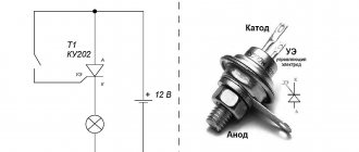
The concept of relay protection and automation (RPiA)
Rules for technical operation and installation of electrical installations (PUE, PTE) regulate the use of relay types of protection. These devices, or rather complexes of special elements, are often combined with automation, therefore they are abbreviated as RZiA (and this is also an abbreviation without “and” or RZ).
According to PTE standards, power units and lines of electrical installations - power plants, substations, electrical networks - are protected from short circuits (short circuits), abnormal conditions, overloads by relay protection and automation units. Such devices are integrated into structures, are part of them (installed at the design stage), and less often - they are mounted separately. According to the rules, they must be in a constant state of readiness (waiting), with the exception of those withdrawn from operation according to the characteristics of their tasks, design principles, modes of power facilities, and selectivity requirements. Alarm units (warning and reporting the development of breakdowns) must also always be ready for activation.
Relay protection and automation are installed at power plants, generators, at any electrical installations, on similar large-sized powerful devices, that is, the scope of use is not limited if relay protection is required by the project. The scope of application is specified by the PUE:
Contents of Chapter 3.2 PUE:
We will explain what relay protection is more specifically, describing its purpose. When using electrical equipment and networks, there are always risks of their damage, incorrect modes, often they cannot be avoided, or such conditions are characteristic of the operation of the power plant. The most critical are overloads and short circuits. Reasons: breakdowns, damage to insulating parts, ruptures, worker errors, for example, disconnection of components under load, incorrect supply of voltage to grounded structures.
A short circuit in the area where it occurred provokes the appearance of an electric arc, the thermal effect of which leads, as a rule, to the irreversible destruction of current-carrying elements, insulating parts, and electrical devices in general (less often, but such cases are very common). In this case, high short circuit currents of thousands of amperes are supplied to the damaged segment. Almost instantaneous heating occurs; in seconds the elements heat up. Thermal processes also damage serviceable areas, causing a problem to develop and a fire to occur. On connected highways and objects, the parameters of electricity are deeply reduced, which causes electric motors to stop, and the functioning of parallel structures and generating devices is critically disrupted.
In the situations described, it is important to immediately stop the development of consequences; usually this is enough to completely prevent accidents. This is achieved by promptly disconnecting the dangerous section of the power plant, network - with automatic devices that function to disconnect contacts and de-energize. This is relay type protection, also known as relay protection or relay protection.
The relay deactivates the switches of the structure with the malfunction, while the electric arc goes out or does not even have time to arise. The flow of short-circuit amperes instantly stops, and at the same time, normal electricity levels are restored on the working part of the power plant or in the network. Damage to short-circuit equipment is minimized and eliminated, and the operating equipment mode is normalized.
Tasks:
- identifies the short circuit point, the location of the breakdown;
- quickly provides automatic shutdown, separates equipment with an unsafe factor, a dangerous segment from working structures and networks;
- detects a problem and reports it, warns about the possibility of an accident;
- creates a delay before deactivation if necessary.
Other disturbances in the power plant are also possible: overload, short circuits of various kinds, the formation of gas masses in transformers, a decrease in oil volume there, etc. If such problems are not dangerous, they correct themselves, and immediate de-energization may not be required. Usually, if the installation has constant maintenance by specialists, issuing a notification to them is sufficient. In other cases, switching off is enough, but with a pause.
Relays RZ are devices, units with an automatic principle that carry out a change in a characteristic periodic type (“relay action”, intermittently) with an established transformation (modification) of the observed characteristics.
Simply put, when detecting violations of the parameters of the power plant, the relay de-energizes and separates the contacts. Example: when the ampere on the controlled circuit critically increases (its current winding is wound there) the relay disconnects the connections to the prescribed mark.
A relay protection device is an interacting system of relays and auxiliary, automatic, device units that turn off equipment when it is damaged or under abnormal conditions.
Relay protection design
Relay protection in its structure has the following elements:
- To control processes in electrical appliances and detect accidents in the electrical circuit, special starting elements are used - these are: a relay that responds to changes in power; a relay that responds to changes in current and a relay that responds to changes in voltage.
- Start other devices, give a signal as a result of detecting problems, and quickly turn off devices - all this can be done by measuring elements. They can also be located in the starting elements.
- The area containing timers, intermediate and indicating relays is called logical.
- The area responsible for turning equipment on and off is called executive.
- Certain types of relay protection contain transmitting elements. They can be found in differential phase.
In this article, we tried to consider in detail why RP is needed, what requirements are placed on it and where it is used.
What is it for?
Very often during operation of electrical systems a short circuit occurs. However, along with this, various voltage surges, current leaks, etc. can occur.
And even if such situations do not cause instant destruction of devices/objects/premises, that is, they do not pose a safety threat, then the protective devices do not act to turn them off, but to warn the personnel on duty about damage.
This is the purpose of relay protection and electrical automation.
Automation
Electrical automation, unlike relay protection, not only turns off the equipment, but also turns it on. First of all, these are auto-on: restart (reclose) and power reserve (ABP).
There are also varieties with personnel control of relay protection equipment, these are automatic:
- regulation of the activation of generators, synchronous motors (ASM);
- for circuit breakers (AUV), for redundancy of their failures (breaker failure protection);
- control of CT switch positions (ARNT);
- setting up arc suppression windings (ARC), static capacitors;
- transformer cooling;
- adjustment (synchronization) of generators;
- frequency start of hydrogenerators (HG);
- identification of circuit fault locations (OCF).
Emergency:
- mode: frequency. unloading (AFR)
- activation of deactivated AFR systems (DFA);
- automatic control of frequency and operating power (ARFC);
- automatic voltage unloading (DARN); by current (DART);
- unloading;
Design features of relay protection
The relay protection device is continuously improved thanks to the introduction of innovative technologies. But the basic principles and design elements remain unchanged.
The structure of relay protection can be represented as a diagram:
Electrical signal – Process monitoring module – Logic and analysis unit – Execution unit – Signal unit
The monitoring unit monitors all electrical processes using current and voltage transformers that carry out measurements. In the logic and analysis unit, incoming signals are compared with the maximum settings. The protection will work even if there is a slight overlap between these values. The execution unit is always in a ready state, waiting for a signal from the logical unit. The signal unit operates using light or sound.
When the full protection activation cycle has passed, the specialist manually returns the device to its original state.
Device
Let's consider the device in the process of describing the operation of relay protection and automation:
| Name | Function |
| Monitoring unit | Electrical process tracking. Parameters are measured by VT/CT and units with similar functions. Output pulses can be sent directly to the logic part for comparison with user-defined deviations from the settings (normal values). And also impulses can be pre-created messages in digital form. |
| Logical part | Compares received pulses with settings. A discrepancy is determined, and a decision is made on commands to activate the protection. |
| Executive scheme | Constantly in a state of readiness to receive commands from the logical part. Switches power supply circuits according to a prescribed algorithm to prevent equipment breakdowns and electric shocks. |
| Signal node | The user himself cannot adequately monitor extremely fast processes in the electronic device with his senses. To save data from ongoing processes, warning devices (image, sound, light) are used, which also record history in memory. After such devices are triggered, they are set to their original position manually. The system allows you to save data on all actions. |
Kinds
First, we will separately describe the logical protection for buses, abbreviated as LPS. Principle: compares the state of protection of supply parts and outgoing feeders (cable outlets). Sample algorithm: the protection on one of the last ones was turned off, which means there is a short circuit on it; did not start on them at all - short circuit on bus elements. In the event of a short circuit on the tap, protections (current releases) are activated on it and on the power nodes of the section (CT inputs, segment switches).
It will be interesting➡ Three-phase voltage. How does three-phase voltage differ from single-phase
Further, upon triggering, the power parts are switched off without a pause. In the event of a short circuit on the bus parts of the distribution circuit, the relay protection on the taps does not start, and when activated on the supply nodes, it is allowed without delay.
Other types of relay protection:
| View | Description |
| Max. current (MT) | Trip factor - determination of the number of Amperes (set). |
| Directional max. (MTZ) | Additionally controls the direction of power. |
| Gas (GZ) | To deactivate CTs and VTs in the event of internal breakdowns accompanied by the formation of gases. |
| Differential | On generating units, VT, CT, buses. The currents are compared at the input. into the protected structure and at the exit, the system registers the difference and if the limit limits of the setting are violated, it is triggered. |
| Remote (DZ) | It is activated when the resistance decreases, which is typical during a short circuit. |
| Remote sensing with RF blocking | Together with earth fault protection (GF). For faster de-energization during short circuit. If there is a serviced overhead line with input. and out. DZ and ZZ, then the short circuit on such a line is usually deactivated by levels 1–3 of this system with a pause from 0 to several seconds. And HF blocking of remote protection and external protection creates a 2-way shutdown of the section without a pause for all possible short circuits in any locations. |
| Remote sensing with optical cable blocking | A high-quality replacement for the previous version. The need to maintain HF equipment is eliminated, reliability increases, since optical instruments are more stable and less susceptible to interference. |
| Dugovaya | To prevent ignition of switchgear, KTP 6.3 and 10.5. Mounted at the connection points, it is triggered by increased illumination through optical detectors, as well as by excessive pressure through sensors (valves) for this parameter. It is possible to respond to current protection (its control), used to exclude false activations. |
| Differential-phase (DPZ) | It's high frequency. The principle is to control the phases and operate when the number of Amperes on them violates the setting. |
Basic requirements for relay devices
The main properties of the relay are as follows:
- Selectivity. This parameter is characterized by the system’s ability to turn off damaged areas, while undamaged elements remain on. There are two types of relay: the first is relay with medium selectivity (overcurrent and distance protection); the second is protection with complete selectivity (differential protection).
- Relay response speed (response speed). If the response speed of the system is high, then the likelihood of any damage or accidents will be lower. The period of time after the occurrence of an accident and before the damaged device is switched off from the network is called the relay protection response time. This is the main indicator of this parameter.
- The ability of the relay to respond even to minor emergency parameters is called the sensitivity of the relay. This parameter can be assessed using the sensitivity coefficient.
- The property in which a relay protection device operates for a certain time with the specified functions is called reliability. There are two main indicators of this parameter: the number of deviations per unit of time and the period of time of correct operation.
That is, the purpose of a relay protection and automation system with the above properties is that the device should signal an operating signal about damage, instantly disconnect a broken element from the power supply, quickly respond to any changes during operation, and generally provide control over the operation of electrical appliances.
Management nuances
The relay protection is performed as a separate unit and is an independent circuit, despite the fact that it is often integrated into the design of the power plant itself. Such nodes are included in general complexes that make up the emergency control system of the power system, where all nodes are interconnected and implement assigned tasks together.
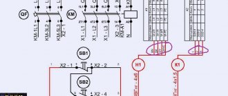
Below is a diagram (simplified) of the functions and actions of the automation:
Relay protection classification
The relay classification system is quite diverse. Next, we will look at the main characteristics by which relays (electrical switches) are divided:
- By type of connection: electrical switches connected to the network without any auxiliary devices are called primary; relays connected using auxiliary devices (for example, a voltage transformer) are called secondary.
- By type of operation: relays that have moving components are classified as electromechanical/induction relays; electrical switches without moving components are called static (for example, electronic, microprocessor, etc.).
- By type of purpose: electrical switches that carry out measurements of various physical quantities - this is a measuring relay (for example, current, temperature, power, etc.); mechanisms that transmit action to other devices are called logic/auxiliary relays. The last group of relays is also capable of withstanding time, etc.
- According to the type of action on the controlled component: an electrical switch connected automatically to the device being switched off is classified as a direct-acting electrical switch; relays that regulate the electrical circuit of electromagnets, turning off the switching device.
If we talk about relay protection, then there are a large number of types of relay protection, for example:
- Protection of electrical appliances and electrical circuits, which is triggered when a predetermined value of electric current is exceeded, is called relay current protection. This includes: maximum relay current protection (MCP) - provides protection of devices from current that exceeds the rated value. Current cut-off (TO) - quick elimination of short circuits that appear in front of the work area. Directional maximum current protection (NMCP) - in this case, power direction control is added to the protection of relay devices from currents.
- If the temperature in the transformers rises, which is accompanied by the formation of gases and as a result, the power supply to the devices from the network is cut off. This type of protection is called gas protection.
- A protection based on a comparison of the current in front of the protected section and the current at the end of this section is called differential protection.
- Determining the distance to the point of occurrence of a short circuit using resistance, such relay protection is called distance protection. There are two subtypes of distance relay protection: 1) using blocking and high frequency; 2) using blocking through the optical channel.
- Relay protection based on the response of an optical sensor due to strong lighting and a sensor due to high pressure, such protection is called arc protection.
- The protection used when determining a short circuit in buses is called logical bus protection (LBP). It is necessary to reduce the time when disconnecting a short circuit.
- The protection based on the comparison of current phases at the ends of the power line is called differential-phase protection (PDP). When the set value is exceeded, the relay is activated.
In addition to the main types of relay protection, below we will talk about the types of automation in relay protection, which, in comparison with relay protection, do not turn off, but turn on the power supply after an accident.
- Automation, which is used to turn on an entire line or a separate phase of the line after it has been disconnected due to the applied protection, is called automatic reclosure (AR). There are two subtypes of automatic reclosure: mechanical and electrical. They are used in power lines with voltages over 1 kV, as well as in the assembly of substation busbars, electric motors and transformers.
- Automatic switching on of a reserve (ATS), the purpose of which is an uninterrupted supply of electricity to devices and allows you to instantly switch on backup equipment.
- If the frequency in the power supply network decreases and at the same time third-party electrical appliances are switched off, then this type of automation is called automatic frequency unloading.
It will be interesting➡ Electrical engineering for dummies. How to learn to understand electrics: lessons for beginners
We have told you a small part of what purposes and in what areas RP is used. Now it remains to consider the design of the relay protection.
Scheme
There are extremely many varieties, combinations, and places of relay protection on networks and in electrical installations. There are also standardized options, original templates - circuit diagrams. But regardless of the complexity, any drawing can be understood only by learning to read it. This skill is necessary to work with relay protection and automation equipment.
In terms of importance and complexity, the “principles” of relay protection and automation kits are second in the design of the entire electrical equipment system. In all cases, when developing or testing finished circuits, at least minimal skills in electrical engineering will be required. Even specialists sometimes find it difficult to understand the relay protection circuit at the elementary input of 10 kV transformers, not to mention in general for a 110/10 kV substation.
Let's look at a technique that makes drawings easier to understand. The method described below is standard and common; it does not harm the quality of the analysis.
Breaking down the diagram into parts
The whole scheme is extremely difficult to understand, so it is conditionally divided into separate sections and analyzed each separately.
Let's consider relay protection and automation with terminals on microprocessors, divide the drawing into 10 positions:
- explanatory;
- circuits: measurements (current, voltage);
- switch mechanism;
- involved current (operational), including power supply to the terminal;
- alarms;
- weekends, including TC and reserve;
- ACS;
- auxiliary (heating, light, sockets, etc.);
Not every set of RP contains all 10 positions, but the absence of any must be justified; if this cannot be done, then there is an error in the diagram.
This method is a kind of checklist, an analysis system. The results obtained can be recorded in a list with checkboxes opposite the items and transferred to the contractor before design.
Test example: the absence of a drive circuit in a 10 kV VT (position 2 in the “circuits” section of the list) is justified by the fact that the latter’s cell does not have a switch, and this is logical. If there is no answer to the question posed, for example, why there is no parameterization data for the 10 kV input into the relay protection, then there is an error, especially for terminals with flexible logic.
Typical circuit errors:
- in current circuits - incorrect polarity when connecting the CT to the terminal;
- drive circuit - platoon (ready for activation). There may be incorrect closing or opening. It is necessary to check by comparing it with the terminal algorithm;
- operational current circuits - control keys, control mode (MU/DU);
- Arc protection circuits, generation designs are particularly susceptible to such complex faults.
Example of diagram breakdown and reading
To explain, we took a popular example from the Internet; there are also video materials for it on the Internet. We will show the circuit in parts (connected in a horizontal plane), since it is quite large.
Drawing for a relay protection with electromechanical relays, a VVTEL Tavridaelektrik switch (without a terminal, this is not a digital design on microprocessors) of a 10 kV line at a 110/10 kV substation:
Second part of the diagram:
Third part of the diagram:
The diagram is available online; to open it you will need special drawing programs. Next, let's select and show the parts.
Explanatory diagram:
Measuring circuits (electromechanics, MTZ, MTO, power circuits from the alternating opercurrent of the switch drive, converter counters):
Drive circuits (power supply and control unit, electromagnet circuits):
Operating current circuits (automatic circuit breaker, executive relays, power supply):
Arc protection refers to opercurrent circuits:
Emergency and warning light circuits, central (below):
Output circuits (in this case this is what is included in the remote alarm):
Auxiliary circuits:
List of elements:
In this example, there are no logic tables, parameterization data, ACS circuits, or parallel automation protection, since this relay protection does not have a terminal and is not based on microprocessors.
Main tasks of selective protection
Selectivity is a process that means selection (selection). This term is applicable to different industries and areas of human activity. For example, in chemistry, when chemical reactions occur, they talk about the selectivity index. In this case, the selectivity of chemical transformations is considered.
As for a person, his perception of the world around him, the choice of information, as well as its memorization are selective.
What is selectivity in electrical engineering, and why is it needed?
The tasks of electrical selective protection include:
- guaranteeing the safety of equipment and operating personnel;
- instantly identifying the location of the fault and disconnecting only the faulty section;
- reducing the negative effects of the accident on other components and parts of electrical appliances;
- minimizing damage to the faulty area;
- guaranteeing maximum continuity of operation of the electrical system;
- achieving ease of operation of electrical equipment.
In addition, selectivity reduces the consequences of short circuits and the load on the device.
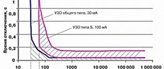
Selectivity map and rules for its creation
The diagram of the approved sample, on which all current parameters of protective devices and devices are plotted, indicating the common power source, is carried out on a scale convenient for viewing. This is a selectivity map. It ensures maximum use of the protective qualities of circuit breakers. All processes possible during operation are displayed graphically.
The following must be included on the map:
- places of important calculation points;
- protective characteristics of automatic circuit breakers and possible short circuits, while their min and max values are indicated.
This map serves as the basis for compiling a table for the selection of protective devices. In addition, the map allows you to evaluate the overall protective selectivity and provides complete information about the mutually agreed upon settings of all machines.
The map is constructed along axes. The abscissa axis represents current values, and the ordinate axis represents time values.
For your information. Other types of characteristics can be applied to the axis. Each scheme includes the parameters of two or three machines. The construction of such maps can be done using a computer program.
An example of a selectivity map made using the program
Properly executed selective protection allows you to preserve equipment. When a specific section is turned off, it allows you to turn the power back on using an automatic transfer switch (ATS) and minimize equipment downtime and interruptions in the supply of electricity to consumers.
Calculation of selectivity of machines
In most cases, protection devices are not some kind of tricky devices, but standard and well-known circuit breakers. To provide them with the correct selectivity, you just need to select the right parameter settings. The operation of such units is based on the following condition:
Is.o.last ≥ Kn.o.* I k.pred., where:
- Is.o.last - the current at which the protection begins to operate;
- I k.pred. — short circuit current at the end of the protective zone;
- Kn.o. — reliability coefficient, which depends on a number of settings.
You can calculate selectivity when controlling devices over time using the following scheme:
tс.о.last ≥ tк.prev.+ ∆t, where:
- tс.о.last and tк.prev. — time intervals through which the circuit breakers are triggered in order of proximity to the power source;
- ∆t is the time step of selectivity.
Selectivity principle
This principle was invented so that when a problem is detected in a particular area, not all areas are de-energized, but only those where a problem situation was detected.
This principle helps to maintain work in the enterprise without disrupting the entire work process.
Selectivity tables
Selective protection operates mainly when the In rating of the circuit breaker is exceeded, i.e., under small overloads. With short circuits it is much more difficult to achieve. To do this, manufacturers sell products with selectivity tables, with which you can create bundles with selectivity of operation. Here you can select groups of devices from only one manufacturer. Selectivity tables are presented below; they can also be found on enterprise websites.
To check the selectivity between the upstream and downstream devices, the intersection of the row and column is found, where “T” is complete selectivity, and the number is partial (if the short-circuit current is less than the value indicated in the table).
Operating principle of differential protection
The basis of the operating principle of any differential protection is the control of currents at the beginning and end of the protected section of the electrical circuit. Current transformers are used for this. When located within the same switchgear, they are connected to the protection device directly using cables. If the boundaries of the protected area are located at a large distance from each other, which is typical for cable or overhead lines, two half-sets of protection are used, connected to each other by an auxiliary cable line.
If these currents at the beginning and end of the protected section are equal to each other and directed in one direction, no operation occurs. This happens when rated load currents flow or during a short circuit outside the protected area (external short circuit currents).
But if the damage occurs in an area controlled by the protection, the power of the electrical network flows to the short circuit point. With one-way power supply (for transformers or generators), more current flows from the source towards the protected electrical device than is given to the consumer. With two-way (on a cable or overhead line connecting networks with independent power sources), the currents at both ends of the line are oriented to the point of damage.
A reason is created for the protection to operate, which gives the command to turn off the object simultaneously from all sides.
Depending on the characteristics of the protected object, appropriate differential relays are selected for the implementation of devices. Let's consider their features.
It will be interesting➡ Making conductive glue from scrap materials
Details about the operating principle of the differential. protection, watch the video:
Disadvantages of radio relay communication
There are not many disadvantages to RRL, but they are also worth mentioning:
- The complexity of the equipment, as well as the large dimensions of the installations;
- To be truly useful, antennas must be mounted on tall structures;
- Intermediate equipment may reduce signal quality;
- There must be a direct geometric line of sight between adjacent antennas;
- In some conditions, erecting towers may be too complex and therefore expensive.
Without exaggeration, radio relay communications can be called one of the most important inventions of the twentieth century. It was thanks to RRL networks that for the first time it became possible to transmit large amounts of data over long distances without the use of wires.
Purpose of automatic reclosing
Purpose of automatic reclosing
Automatic reclosing is designed to close circuit breakers after a fault has de-energized a line. At the same time, automatic reclosure makes it possible to reduce interruptions in power supply by the number of short-term accidents. Look at Figure 1, in the event of a short circuit at point K1 followed by tripping of the high-voltage switch Q1, automatic reclosure 1 is triggered. Let’s assume that the short circuit has resolved itself and the supply to the line from substation PS1 to PS2 has been restored.
At the same time, when there is a short circuit at points K2 and K3, switch Q2 cuts off the line to substation PS3. Let’s assume that these are established short circuits; when autorecloser2 is triggered, the voltage will be supplied to the network again, but since a short circuit occurs at points K2 and K3, Q2 will turn off the line again.
Therefore, all emergency situations according to their duration can be divided into:
- Short-term - those that are caused by a relatively short-term factor (movement of animals, falling branches and other elements), which created the flow of short circuit currents for a fraction or a few seconds, after which both the cause and the circuit eliminated themselves.
- Established - caused by a constant factor that cannot go away without personnel intervention (wire breakage, insulation destruction, etc.). In such situations, persistent short circuits occur, which can only be eliminated by turning off the switches and subsequent repairs.
In practice, automatic re-closing works in all situations, but successful re-closing only occurs when the cause has been eliminated, that is, in the case of short-term faults. If, after the first restart, automatic recovery does not occur, depending on the type, the following restart stages may be applied. Depending on local conditions, automatic reclosure systems may have different operating features.
Since 50% of all outages can be re-energized with a single autorecloser, the first stage is considered the most effective. The second is adjusted with a time interval of several seconds or tens of seconds, and, as statistics show, it allows the consumer to be powered in another 15% of cases.
Requirements
To ensure the declared modes and safe operating conditions of the equipment, a number of requirements are imposed on automatic restart devices:
- Performance – must ensure the transition speed determined by the type of powered devices and consumer category. But, at the same time, the speed should not restart until the electric arc has completely dissipated. Because otherwise, even with short-term damage, re-ionization of the insulating gap is possible.
- Resistance to emergency mode - TAVR and backup protection devices should not reduce the quality and speed of response due to changes in electrical quantities.
- Automatic reclosure selectivity - the system must adjust its operation in accordance with other emergency automatic devices, without interrupting the operation of the protection.
Figure 3: Coordination of automatic reclosure with other protections - In case of operational shutdowns for the purpose of carrying out scheduled work, the automatic recloser must be removed from the circuit so as not to mistakenly apply voltage to the substation busbars and not endanger personnel.
- After the reclose has been triggered, the switching device must return to the closed position. If the reclosure is unsuccessful, there should be an automatic return to the open position.
- For some types of protection (gas, differential and others that react to damage to the transformer), a ban on restarting should be established. Also, the disabled position must be maintained in the event of an emergency mode in power electrical machines.
- When restarting, uncontrolled multiple reclosures must be blocked in order to avoid the destructive effects of sustained short-circuit currents on devices.
Increase in current during short circuit
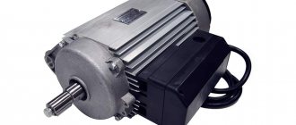
Relay protection cabinets
Modern microprocessor-based relay protection devices perform not only their direct protection tasks, but also other related functions. Thus, today a large number of devices can be equipped in one cabinet, which greatly simplifies the installation of equipment, direct operation, and also significantly frees up space.
Standard protection cabinets have a number of additional advantages: since the cabinets are made according to standard designs that have been tested in operation, the likelihood of errors in operation is significantly reduced, and the ease of commissioning and installation increases. Find out even more about relay protection and standard solutions on our website.