Good day everyone! When calculating and designing a transformer, it is necessary to take into account the electromagnetic characteristics and features of its design with thermal and geometric characteristics. Therefore, the main task in design is to analyze the specified properties and determine the optimal dependencies that guarantee obtaining the required result.
In the last article I looked at the geometric characteristics of the transformer, in this article I will talk about the electromagnetic parameters.
To assemble a radio-electronic device, you can pre-make a DIY KIT kit using the link.
The given transformer parameters
For theoretical analysis of a transformer, it is not very convenient to use real values of the main parameters of the transformer. To do this, use the given parameters that characterize the transformer if the number of turns N of the primary w1 and secondary w2 windings is equal. Usually the reduction is carried out to the primary winding. To convert real parameters to given ones, a transformation coefficient k is used equal to
The number of turns is adjusted together with the actual values of the main parameters.
The main parameters include the resistance of the windings R, their voltages U and currents I, as well as the resistance of the magnetizing circuit, which characterizes the transformer core. The designation of the given values is usually accompanied by a top stroke
The point of the reduction is that the number of turns does not affect the operating principle of the transformer, but for analysis it is more convenient to use the same number of turns.
4.10.WINDING CONNECTION GROUPS
Until now, we believed that when constructing a vector diagram, the emfs E1 and E2 are in phase. But this is true only if the primary and secondary windings are wound in the same direction, or their terminals are marked with the same name (Fig. 4.10.1, a).
If you change the winding direction of the windings in a transformer or rearrange the designation of their terminals, then the EMF vector E2 will be shifted relative to the E1 vector by 180° (Fig. 4.10.1, b). The phase shift between EMF E1 and E2 is usually expressed by a group of connections. Since this phase shift can vary from 0 to 360°, and the shift factor is usually 30°, a series of numbers from 1 to 12 are selected to designate connection groups, in which each unit corresponds to a shift angle of 30°. This is based on a comparison of the relative position of the vectors E1 and E2 with the position of the minute and hour hands of a clock. Winding vector V.N. is considered to be the minute hand set at 12, and the vector N.N. - clockwise. By the position of the clockwise relative to the minute hand, the position of the EMF vector of the N.N. winding is determined. relative to the V.N. winding So, in Fig. 4.10.1, and the connection has group 12, and in Fig. 4.10.1, b - group 6. Thus, in a single-phase transformer there are only two groups -12 and 6. In a 3-phase transformer, the connection group is determined by the phase shift angle between the linear EMF vectors E1 and E2. GOST limits the use of only two groups: Y / Y - 12 and Y / - 11. As an example, consider the Y / Y - 12 scheme (Fig. 4.10.2).
The vector diagram shows that the shift between E1 and E2 is zero or 360°, i.e. (360° / 30° - 12 group). If we change the beginnings and ends of the N.N. windings, then we will have group 6 (Fig. 4.10.3).
Transformer equivalent circuit
The basis of the transformer equivalent circuit is the fact that the secondary current does not create the main magnetic flux in the core. Since this is counteracted by the load part I of the current of the primary winding, which has the same magnetizing force as the current of the secondary winding I2 but opposite in direction. And the main magnetic flux is created by the magnetizing part I0 of the primary winding current.
The secondary winding current I2 and the load part I of the primary winding current create magnetic leakage fluxes, indicated in the equivalent circuit by reactances x1 and x2.
Transformer equivalent circuit.
Based on these principles, an equivalent transformer circuit, or as it is also called an equivalent circuit, is constructed. A transformer with one secondary winding is shown here and has the following designations: ZH - load resistance, ZI - internal resistance of the signal source, EI - source emf, E - reduced winding emf, xCi - capacitance of the transformer windings, XL - inductive reactance of the magnetizing circuit, RC – active resistance of the magnetizing circuit.
Equivalent circuit taking into account magnetic losses
Losses in the steel of the magnetic circuit pMG at a given frequency are proportional to the following quantities:
pmg ∼ Bc2 ∼ Фc2 ∼ E12.
Thus, the losses pmg are proportional to the square of the voltage U12 at terminals 1 – 2 of the magnetizing circuit of the equivalent circuit in Figure 1, a. If an active resistance rmg is connected to these terminals in parallel with x12' = xc1, as shown in Figure 2, a, then the losses in this resistance will also be proportional to U12. The resistance value rmg can be selected so that the losses in it are equal to the magnetic losses:
pmg = m1 × U122 / rmg = m1 × E12 / rmg.
From here
| rmg = m1 × E12 / pmg. | (26) |
Figure 2. Magnetizing circuit of an equivalent circuit taking into account magnetic losses
The value of pmg at a given electromotive force E1 can be considered known from calculated (see the article “Calculation of the magnetic circuit of a transformer”) or experimental data. Then rmg can also be considered known.
Magnetizing current
is divided in two branches of the magnetizing circuit (Figure 2, a) into active Ima and reactive Imr components (see the article “Calculation of the magnetic circuit of a transformer”), of which the first determines the power of magnetic losses, and the second creates the flux of the magnetic circuit.
The circuit with two parallel branches of the magnetizing circuit is in good agreement with real physical phenomena. However, it is more convenient to carry out calculations based on an equivalent circuit if you combine two parallel branches of circuit 2 into one common branch, as shown in Figure 2, b. Then the resistance of this branch
| (27) |
Since rmg >> x12', then
| (28) |
With increasing saturation of the magnetic circuit, that is, with increasing Fs, E1 or U1, the resistance x12' at f = const decreases. However, in this case rm ≈ const, and the value of rm decreases.
The equivalent circuit of the transformer taking into account magnetic losses according to Figure 2, b is shown in Figure 3, a. If we use the notation
| Z1 = r1 + jx1 ; Z2' = r2' + jx2' ; Zm = rm + jxm, | (29) |
| Figure 3. Equivalent circuit of a two-winding transformer taking into account magnetic losses |
then the equivalent circuit can be depicted more compactly, as shown in Figure 3, b. In no-load mode, I2' = 0 and I1 = Im – the no-load current of the transformer.
The result was a very simple T-shaped equivalent circuit of the transformer, which is a passive four-terminal network. The resistance of the magnetizing circuit of this circuit Zm reflects the phenomena in the ferromagnetic magnetic circuit. It is significantly greater than the resistances Z1 and Z2', which include active resistances and inductive leakage resistances of the windings. For power transformers in relative units
zm* = 25 – 200; z1* ≈ z2*' = 0.025 – 0.10.
Voltage equations and the equivalent circuit of a transformer can also be represented in relative units. Bearing in mind that
Un = zn × In ,
the left-hand sides of equations of the form (15) can be divided into Un, and the right-hand sides into Zн × In, as a result of which the transition to relative units will be made. The absolute values of U, I, r, x and Z in equivalent circuits can also be replaced by relative ones. In this case, calculations of the operating modes of the transformer can be carried out in relative units.
It is easy to see that the relative values of the resistances, currents and voltages of the secondary circuit will depend on what value of the coefficient k was used when bringing the secondary winding to the primary. The uncertainty in this matter disappears if k is always determined in the same way. For example, in power transformers they always take k = w1 / w2.
Currents in the equivalent circuit of a transformer
In accordance with the diagram, the magnetizing current I0 consists of two parts: reactive I0r, which ensures the creation of magnetic flux Φ (Φ = I0rw), and active I0a, which affects power losses in the core Рс (Рс = I0a2RC).
Then the following relations take place for the magnetizing circuit
Due to the nonlinearity of the transformer core parameters, the XL and RC values are inconvenient to use. For calculations, the magnetic characteristics of the core and the dependences on induction B of the following parameters are used: the effective strength of the magnetizing field NE (A/m), the specific magnetizing power of the core p0 (W/kg) and the specific losses pi (W/kg). Then, based on the known weight of the core Gc and the effective length of the magnetic field line lE, we determine the losses in the core PC = piGc and the magnetizing reactive power Р0L = p0Gc
When analyzing the operation of a transformer, it is more convenient to use relative values of currents, most often relative to the load current I. Then the relative currents will be designated: the active component Ia of the current I through ia, the reactive component Ir through ir, the primary winding current I1 through i1, the magnetizing current I0 through i0 and its components are i0r and i0a. They will be determined by the following expressions
Transforming the previous expressions we get
Since in most cases the transformer is dominated by active load Ir≈0, the relative current of the primary winding will be
In the case of insignificant losses in the core i0a<< i0r we obtain
4.7. VECTOR DIAGRAM OF TRANSFORMERS
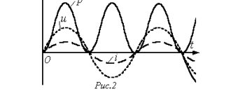
It is more convenient to start constructing a vector diagram with the vector of the main flow F. Let us plot it along the abscissa axis. Vector I10 advances it by angle a. Next, we construct the EMF vectors E1 and E2′, which lag behind the flux Ф by 90°. To determine the phase shift angle between E2′ and I2′, you should know the nature of the load. Let's assume it is active-inductive. Then I2′ lags behind E2′ by angle f2. The result is a so-called vector diagram blank (Fig. 4.7.1.). In order to complete it, it is necessary to use the three basic equations of the given transformer.
Let's use the second basic equation:
and perform vector addition. To do this, we attach the vector - j I2′ x2′ to the end of the vector E2′, and the vector - I2′ r2′ to its end. The resulting vector U2′ will be the vector connecting the origin to the end of the last vector. Now we use the third basic equation
from which it is clear that the current vector I1 consists of the geometric sum of the vectors I10 and - I2′. Let's perform this summation and complete the vector diagram. Now let's return to the first basic equation:
To construct a vector - E1, you need to take the vector +E1 and direct it in the opposite direction. Now you can add other vectors with it: + j I1 x1 and I1 r1. The first one will go perpendicular to the current, and the second one will go parallel to it. As a result, we obtain the total vector u1. The constructed vector diagram is of a general nature. Using the same methodology, it is possible to construct it both for different modes and for different types of load.
Resistances in the equivalent circuit of a transformer
Let's consider the resistance of the windings in the equivalent circuit. In different types of transformers, certain types of resistance may have different significance. In most cases, active resistances Ri are of primary importance. However, in powerful transformers the leakage resistance Xi is significantly higher than the active one. The active resistance of the winding is determined in the standard way, through the resistivity of the conductor ρ, the number of turns of the i-th winding wi, the average length of the turn of the i-th winding lwi (m) and the cross-section of the conductor of the i-th winding qi (mm2)
In the case of transformers of high and high frequencies, the active resistance of the windings begins to increase as the frequency increases. This occurs due to the surface effect (skin effect) and the influence of neighboring winding conductors (proximity effect). These factors are reflected using the additional loss coefficient kr, which I discussed in the article on power losses in chokes.
Let's return to the reactances Xi and Xci. Reactance Xi is caused by leakage fluxes and is calculated through leakage inductance Lsi
where ω is the circular frequency,
f – alternating current frequency.
In most cases it is necessary to know the total leakage inductance Ls reduced to the primary winding. Approximately, it is twice the leakage inductance or reduced secondary winding
where wi is the number of turns of the i-th winding,
lwi – average turn length of the i-th winding, cm,
mф – number of rods carrying the winding of one phase (for ST mф = 2, for the rest mф = 1),
msi – number of winding sections, for an unsectioned winding msi = 1,
h – windings (rod height without yoke), cm,
∆ob – thickness of inter-winding insulation, cm,
Cki – thickness of one coil, on one side (for BT Cki = s, for ST, TT Cki = s/2), cm,
KT – transformation ratio.
The capacitances in the equivalent circuit of the transformer and the corresponding capacitance resistances Xci combine several types: interwinding capacitance Cb, interlayer capacitance Ccl and capacitance C1C between the first winding layer and the core. The following expressions will allow you to calculate different types of containers:
- interwinding capacitance
where εa is the dielectric constant of the substance between the core and the first winding layer,
di – diameter of the winding wire without insulation,
lw – average length of the transformer coil turn,
∆1С – distance between the core rod and the winding closest to it,
wi – number of turns of wire in the i-th winding,
nsl i – number of layers of conductors in the i-th winding.
— interlayer capacity
- capacitance between the first winding layer and the core
a, b – width and thickness of the transformer core rod.
To reduce these capacitances to the primary winding, you must use the following expressions
They are all combined into a total equivalent capacitance Se and brought to the corresponding input.
The reactive parameters Xi, Xci, Lsi and Ci are in most cases parasitic and negatively affect the operation of the transformer. But at low frequencies (up to several kHz) their influence is insignificant and is not taken into account in practical calculations.
4.11. PARALLEL OPERATION OF TRANSFORMERS
When choosing transformers for power supply to a manufacturing enterprise, a dilemma often arises: either install one powerful transformer, or use several of them, together providing the required power. The second option will always be preferable, because... The operating mode of the enterprise during the day is uneven and the power consumption will be different. For example, at night the load will be minimal, because The power consumption consists only of security lighting and several duty objects. During the day, when the main consumers of electricity are working, the power consumption will be maximum. There will be some kind of intermediate regime in the evening. In short, there may be one, two or three transformers in operation. The parallel operation of several transformers is due to the fact that their secondary windings feed a common load. However, not all transformers are capable of operating in parallel. Let us determine the conditions under which it is possible to switch on transformers for parallel operation. Firstly, these are the same primary and secondary voltages on the windings. Secondly, there must be identical circuits and connection groups. In addition, the short circuit voltages specified in the transformer passport are regulated. And, of course, the phase rotation order of parallel operating transformers must be the same. As an example, we give a diagram of five welding transformers connected in parallel, ensuring the operation of 14 welding stations (Fig. 4.11.1).
4.12. SPECIAL PURPOSE TRANSFORMERS
4.12.1. THREE WINDING TRANSFORMER
A three-winding transformer has three windings electrically disconnected from each other, one of which is primary, and the other two are secondary (Fig. 4.12.1).
The primary winding of the transformer is magnetizing and creates a magnetic flux in the magnetic circuit, which penetrates two secondary windings and induces emf E2 and E3 in them. Neglecting the no-load current, we can write the equation for the currents of three winding transformers
those. the primary current is equal to the geometric sum of the reduced secondary currents. The expediency of using three-winding transformers is also explained by the fact that one three-winding transformer actually replaces two two-winding transformers. The rated power is taken to be the power of the primary winding. Multi-winding low-power transformers used in radio devices, communications and automation are constructed using the same principle.
4.12.2. AUTOTRANSFORMER
In an autotransformer (Fig. 4.12.2), part of the turns in the V.N. winding used as an N.N. winding, i.e. in the autotransformer there is only one winding, part of which (a X) belongs simultaneously to the sides V.N. and N.N.
A current i12 = i2 - i1 flows in the section aX, or moving to the actual values, taking into account that I1 and I2 are in antiphase, we can write
Thus, the current value in the common part of the windings is equal to the difference between the currents I1 and I2. If the transformation coefficient is close to unity, then I1 and I2 differ little from each other, the difference between them will also be small. This will allow part of the aX winding to be made with a wire of a smaller cross-section. The power transmitted by the primary winding to the secondary circuit of the autotransformer will be equal to:
Considering that , it can be written as:
Here U2 I1 = SE is the power supplied to the secondary circuit electrically, U2 I12 = Sм is the power supplied to the secondary circuit through magnetic flux. Consequently, in an autotransformer only part of the power is transmitted through magnetic flux, which makes it possible to reduce the cross-section of the magnetic circuit. Magnetic losses are also reduced. With a smaller cross-section of the magnetic circuit, the average length of the winding turn decreases, therefore, the consumption of winding copper again decreases and electrical losses are reduced. Thus, an autotransformer has advantages over transformers, such as lighter weight, smaller size, higher efficiency, lower cost, etc. etc. However, these advantages are significant only for the transformation ratio k. At a higher transformation ratio, the following disadvantages occur. These are: large short circuit currents in the case of a step-down autotransformer (when points a and X are closed, the voltage u1 will appear on a small part of the autotransformer turns, which have a low short circuit resistance); electrical connection of the V.N. side with N.N.’s side; requiring increased insulation between the windings and the housing and the resulting danger of contact with V.N. on the side of N.N. Autotransformers can be step-up and step-down, single-phase and three-phase. Autotransformers are used in high-voltage power lines to start asynchronous and synchronous motors in laboratory practice and testing. Voltage regulation is carried out both by switches that change the input number of turns in the secondary circuit, and by means of a sliding contact that moves directly along the turns of the winding.
4.12.3. TRANSFORMER FOR ARC WELDING
The welding transformer is a single-phase transformer that reduces the network voltage to 60-65 V (Fig. 4.12.3.1, a). In operating mode, the transformer is close to a short circuit. To prevent the current value from increasing above the permissible value, a reactive coil RK with a sliding core is connected in series with it, as a result of which the transformer characteristic becomes steeply falling (Fig. 4.12.3.1, b).
By changing the gap d, you can smoothly change the welding current. The maximum current value will be at dmax. For safe maintenance, the secondary winding of the welding transformer is grounded.
4.12.4. CURRENT AND VOLTAGE MEASURING TRANSFORMERS
These transformers are used in conjunction with measuring instruments to expand their measurement limits (Fig. 4.12.4.1). The voltage measuring transformer is a step-down transformer with a turns ratio w1/w2 such that when U1 = Unetwork; U2 = 100 V. The secondary circuit includes voltmeters, frequency meters, voltage windings of wattmeters, counters and phase meters. Since the electrical resistance of these devices is high (about 1000 0m), the voltage transformers operate in a mode close to no-load. This mode is associated with large magnetic losses, and this, in turn, leads to an increase in the size of the magnetic circuit and a special oil cooling device.
Measuring current transformers (Fig. 4.12.4.1) are used to connect ammeters, current windings of wattmeters, meters and phase meters to the network. The primary winding of the current transformer is made of a large cross-sectional wire and is connected in series to the circuit. The secondary winding is always carried out at a current I2 = 5A. The operating mode of the current transformer is close to a short circuit, so the dimensions of its magnetic core are significantly smaller than those of the voltage transformer. To determine the voltage or current in the circuit, it is necessary to multiply the instrument readings by the transformation ratio of the measuring transformers. For safety reasons, the secondary winding of the current transformer must not be left open if the primary winding is connected to the network. In this mode, the voltage U2 increases to several thousand volts. A type of measuring current transformer is a current clamp with a detachable magnetic core, where the role of the primary winding is played by the wire itself, through which the measured current flows.
4.12.5. TRANSFORMER FOR CONVERSING THE NUMBER OF PHASES
To power various rectifiers or electric furnaces, there is a need to increase the number of phase windings of the transformer. Thus, a three-phase network system can be converted into a six-phase or twelve-phase system using a special transformer. In Fig. 4.12.5.1, and the diagram of a six-phase converter is shown.
The primary winding of such a converter is connected by a star, and the secondary by a double star. The vector diagram of the secondary winding of the converter is a six-star (Fig. 4.12.5.1, b).
4.12.6. VOLTAGE REGULATOR
To stabilize voltage in low-power devices (up to 5 kW), electromagnetic stabilizers are used: 1) ferromagnetic saturated type (without capacitance), which use phenomena based on saturation of the ferromagnetic core; 2) ferroresonant (with capacitance), the operation of which is based on the resonance of currents and voltages. Let's consider the operation of a ferroresonant stabilizer. It consists of reactive coil 1, the core of which, at a given voltage range U1, operates in a state of magnetic saturation, capacitor C and autotransformer 2, the magnetic circuit of which is not saturated (Fig. 4. 12.6.1). The autotransformer winding is connected in such a way that the voltage at the output of the stabilizer U2 is equal to the difference
U2 = U2′ - U2″,
where U2″ is the voltage at the output of the autotransformer; U2′ is the voltage at the outputs of the reactive coil.
Voltage U2′, due to the phenomenon of ferroresonance, has a sharply nonlinear dependence on current I1 (curve 1). The voltage at the output of the autotransformer U2″, due to the saturated state of its magnetic circuit, is proportional to the current I1 (curve 2). If the parameters of the autotransformer and the reactive coil are selected in such a way that the slope of curve 1 to the abscissa axis in the region of magnetic saturation is equal to the slope of curve 2, then the difference U2' - U2" = const. In this case, the output voltage does not depend on the current I1 (curve 3) and, therefore, on the voltage U1.
4.12.7. MAGNETIC AMPLIFIER
Magnetic amplifier
is a static device used in automatic control circuits. The operation of the magnetic amplifier is based on the nonlinearity of the magnetization characteristics of the magnetic circuit (Fig. 4.12.7.1).
On the outer rods of the magnetic amplifier there is a working winding, which consists of two coils connected in series. The middle rod houses a control winding consisting of a large number of turns. If no current is supplied to it, and voltage U1 is applied to the working winding, then due to the small number of turns W~, the magnetic circuit is not saturated and almost the entire network voltage drops to the resistance of the working windings ZH. In this case, little power is allocated to the consumer. If we now pass current IU through the control winding, then even with a small value (due to large W=), saturation of the magnetic circuit occurs. As a result, the resistance of the working winding decreases sharply, and the current in the circuit increases. Thus, by means of small signals in the control winding, it is possible to control a significant amount of power in the operating circuit of the magnetic amplifier.
4.12.8. TRANSFORMER FOR FREQUENCY CONVERSION
In school practice, there is often a need to create a high-frequency alternating current source. Using transformers it is easy to build a frequency doubler or tripler. The frequency tripler consists of three single-phase transformers operating with a highly saturated core (Fig. 4.12.8.1). The primary windings are connected in a star, and the secondary windings are connected in series. As is known, the magnetizing current has a complex curve shape and, in addition to the main harmonic component, has a third one, varying with frequency f3 = 3f1. When the primary winding is connected with a star, the currents of the main harmonic are balanced, and under the influence of the third harmonic, the magnetic flux induces a voltage in the secondary winding that changes at triple frequency.