Current is the movement of charged particles and is one of the key characteristics in an electrical circuit. This value is measured in Amperes. Electrical current measures the load on current-carrying wires, buses, and board traces.
Thanks to this value, you can understand how much energy flows in a conductor in a certain amount of time. The value can be calculated in different ways, depending on the data available.
Due to the fact that the solution options and known values may be different, you may encounter problems in the calculations. Next, let's look at how to correctly determine the current strength using different values.
Current strength from a hydraulic point of view
I think you have heard the phrase “ current strength ” more than once.
What is strength needed for? Well, why? To do useful or useless work. The main thing is to do something. Each of us has some kind of power. Someone has such strength that he can smash a brick to smithereens with one blow, while another cannot even lift a straw. So, my dear readers, electric current also has power. Imagine a hose with which you water your garden.
Let's now make an analogy. Let the hose be a wire, and the water in it be an electric current. We opened the faucet slightly and water immediately ran through the hose. Slowly, but still she ran. The jet force is very weak.
Now let's open the faucet to its fullest. As a result, the stream will gush with such force that you can even water your neighbor’s garden.
In both cases the hose diameter is the same.
Now imagine that you are filling a bucket. Which hose will fill it with water pressure faster? Of course from the green, where the water pressure is very strong. But why does this happen? The thing is that the volume of water coming out of the yellow and green hoses in an equal period of time is also different. Or in other words, a much larger number of water molecules will run out of the green hose than from the yellow hose over an equal period of time.
Let's look at another interesting example. Let's say that we have a large pipe, and two others are welded to it, but one is half the diameter of the other.
From which pipe will the volume of water come out more per second? Of course, with the one that is thicker in diameter, because the cross-sectional area S2 of the large pipe is larger than the cross-sectional area S1 of the small pipe. Therefore, the force of flow through the large pipe will be greater than through the small pipe, since the volume of water that flows through the cross section of pipe S2 will be twice as large as through the thin pipe.
Features of a three-phase system
To equip residential buildings and apartments with electricity, two types of circuits are used:
- single-phase;
- three-phase.
The electrical network from power plants comes out with 3 phases, reaches houses in the same form, and then branches into separate phases.
This method of transmitting electricity is considered economical because it reduces losses during transportation.
What is current strength?
So, now let’s apply everything we wrote here about water to electronics. The wire is a hose. A thin wire is a thin-diameter hose, a thick wire is a thick-diameter hose, one might say a pipe. Water molecules are electrons. Therefore, a thick wire can carry more electrons at the same voltage than a thin wire. And here we come close to the very terminology of current strength.
Current is the number of electrons passing through the cross-sectional area of a conductor in any given time.
It all looks something like this. Here I drew a round wire, “cut” it and got the same cross-sectional area. It is through this that electrons flow.
For a period of time take 1 second.
Properties of a three-phase circuit
A three-phase network has a number of advantages:
- reduces losses when transporting electricity over long distances;
- cables and equipment have lower consumption than that of a monophase network;
- the energy system is balanced;
- In the system there are 2 forms of voltage for operation: linear 380 V and phase 220 V.
Current formula
The formula for dummies will look like this:
Where
I - actual current strength, Amperes
N - number of electrons
t is the period of time during which these electrons travel through the cross section of the conductor, seconds
The more correct (official) formula looks like this:
Where
Δq is the charge over a certain period of time, Coulomb
Δt — the same period of time, seconds
I - current, Amperes
What's so funny about these two formulas? The thing is that an electron has a charge of approximately 1.6 10-19 Coulomb. Therefore, for the current strength in the wire (conductor) to be 1 Ampere, we need a charge of 1 Coulomb = 6.24151⋅1018 electrons to pass through the cross section. 1 Coulomb = 1 Ampere · 1 second.
So, now we can officially say that if 6.24151⋅1018 electrons fly through the cross-section of a conductor in 1 second, then the current strength in such a conductor will be equal to 1 Ampere! All! There is no need to invent anything else! Tell your physics teacher so.)
If the teacher doesn’t like your answer, then say something like this:
Current strength is a physical quantity equal to the ratio of the amount of charge passing through the surface (read as through the cross-sectional area) over some time. Measured as Coulomb/second. To save time and according to other moral and aesthetic standards, they agreed to call the coulomb/second Ampere, in honor of the French physicist.
Various quantities used
In addition to the basic quantities: volts, amperes, ohms, watts, multiples, larger or smaller, are used. The following prefixes are used for designations:
- Kilo – 1000;
- Mega – 1000000;
- Giga – 1000000000;
- Milli – 0.001.
Thus it turns out:
- Kilovolt (kV) – thousand volts;
- Megawatt (MW) – million watts;
- Milliohm (mOhm) – one thousandth of an ohm;
- Gigawatt (GW) – a thousand megawatts or a billion watts.
Current strength and resistance
Let's take another look at the water hose and ask ourselves questions. What does water flow depend on? The first thing that comes to mind is pressure. Why do the water molecules move from left to right in the picture below? Because the pressure on the left is greater than on the right. The greater the pressure, the faster the water will flow through the hose - this is elementary.
Now the question is: how can we increase the number of electrons across the cross-sectional area?
The first thing that comes to mind is to increase the pressure. In this case, the speed of water flow will increase, but you won’t increase it much, since the hose will break like a hot water bottle in Tuzik’s mouth.
The second is to install a hose with a larger diameter. In this case, we will have more water molecules passing through the cross section than in a thin hose:
All the same conclusions can be applied to an ordinary wire. The larger its diameter, the more current it can “pull” through itself. The smaller the diameter, it is advisable to load it less, otherwise it will “tear”, that is, it will burn out stupidly. This is the principle behind fuses. There is a thin wire inside such a fuse. Its thickness depends on the current strength it is designed for.
fuse
As soon as the current through the thin fuse wire exceeds the current for which the fuse is designed, the fuse wire burns out and opens the circuit. Current can no longer flow through a blown fuse, since the wiring in the fuse is broken.
burnt fuse
Therefore, power cables, through which hundreds and thousands of amperes “run,” are taken with a large diameter and try to be made of copper, since its resistivity is very low.
Ammeter
We know where the current is directed, how the current is measured, how to calculate it, knowing the charge and the time during which this charge has passed. All that remains is to measure.
A device for measuring current is called ammeter . It is included in an electrical circuit in series with the conductor in which the current is measured .
Ammeters come in very different operating principles: electromagnetic, magnetoelectric, electrodynamic, thermal and induction - and these are just the most common.
We will only consider the principle of operation of a thermal ammeter, because to understand the principle of operation of other devices it is necessary to know what a magnetic field and coils are.
The thermal ammeter is based on the property of current to heat wires. It is designed like this: a thin wire is attached to two fixed clamps. This thin wire is pulled down by a silk thread connected to a spring. Along the way, this thread loops around the fixed axis on which the arrow is attached. The measured current is supplied to the fixed clamps and passes through the wire (arrows in the figure show the current path).
Under the influence of current, the wire will heat up slightly, causing it to elongate, as a result of which the silk thread attached to the wire will be pulled back by a spring. The movement of the thread will turn the axis, and therefore the arrow. The arrow will indicate the measurement value.
Current strength in the conductor
Very often you can see physics problems with the question: what is the current strength in the conductor ? A conductor, also known as a wire, can have various parameters: diameter, also known as cross-sectional area; the material from which the wire is made; length, which also plays an important role.
And in general, the conductor resistance is calculated using the formula:
conductor resistance formula
A table with resistivities of different materials looks like this.
table with resistivity of substances
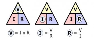
In order to find the current strength in a conductor , we must use Ohm's law for a section of the circuit. It looks like this:
Ohm's law
Task
We have a copper wire 1 meter long and its cross-sectional area is 1 mm2. How much current will flow in this conductor (wire) if a voltage of 1 Volt is applied to its ends?
problem on current strength in a conductor
Solution:
Series connection of resistors.
Let's start by looking at circuits whose elements are connected in series. And although we will only consider resistors as circuit elements in this article, the rules regarding voltages and currents for different connections will also be valid for other elements. So, the first circuit that we will disassemble looks like this:
Here we have a classic case of a series connection - two resistors connected in series. But let’s not get ahead of ourselves and calculate the total resistance of the circuit, but first consider all the voltages and currents. So, the first rule is that the currents flowing through all conductors in a series connection are equal to each other:
I = I_1 = I_2
And to determine the total voltage in a series connection, the voltages on the individual elements must be summed up:
U = U_1 + U_2
At the same time, according to Ohm’s law, the following relationships hold true for voltages, resistances and currents in a given circuit:
U_1 = I_1R_1 = IR_1U_2 = I_2R_2 = IR_2
Then the following expression can be used to calculate the total voltage:
U = U_1 + U_2 = IR_2 + IR_2 = I(R_1 + R_2)
But Ohm’s law is also valid for general voltage:
U = IR_0
Here R_0 is the total resistance of the circuit, which, based on two formulas for the total voltage, is equal to:
R_0 = R_1 + R_2
Thus, when resistors are connected in series, the total resistance of the circuit will be equal to the sum of the resistances of all conductors.
For example for the following circuit:
The total resistance will be equal to:
R_0 = R_1 + R_2 + R_3 + R_4 + R_5 + R_6 + R_7 + R_8 + R_9 + R_{10}
The number of elements does not matter, the rule by which we determine the total resistance will work in any case. And if in a series connection all resistances are equal (R_1 = R_2 = ... = R), then the total resistance of the circuit will be:
R_0 = nR
In this formula, n is equal to the number of elements in the chain. We've figured out the series connection of resistors, let's move on to parallel.
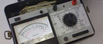
How to measure current?
In order to measure the value of current, we must use special devices - ammeters. Currently, current can be measured using a digital multimeter, which can measure current, voltage, resistance and much more. In order to measure the current, we must insert our device into the open circuit like this.
You can read more details on how to do this in this article.
I also advise you to watch a training video where a very smart teacher explains in simple language what “current strength” is.
Measuring power with a wattmeter
The power consumption of three-phase current is measured using wattmeters. This can be a special wattmeter for a 3-phase network, or a single-phase one connected according to a specific circuit. Modern electricity metering devices are often made using digital circuitry. Such designs are characterized by high measurement accuracy and greater capabilities for operating with input and output data.
Measurement options:
- Star connection with neutral conductor and symmetrical load - the measuring device is connected to one of the lines, the readings taken are multiplied by three.
- Asymmetrical current consumption in a star connection - three wattmeters in the circuit of each phase. The wattmeter readings are summed up;
- Any load and delta connection - two wattmeters connected in a circuit of any two loads. The wattmeter readings are also summed up.
In practice, they always try to make the load symmetrical. This, firstly, improves network parameters, and secondly, simplifies the accounting of electrical energy.
Selecting the rating of the circuit breaker
Applying the formula I = P/209, we find that with a load with a power of 1 kW, the current in a single-phase network will be 4.78 A. The voltage in our networks is not always exactly 220 V, so it would not be a big mistake to calculate the current strength with a small margin like 5 A for every kilowatt of load. It is immediately clear that it is not recommended to connect an iron with a power of 1.5 kW to an extension cord marked “5 A”, since the current will be one and a half times higher than the rated value. You can also immediately “graduate” the standard ratings of the machines and determine what load they are designed for:
- 6 A – 1.2 kW;
- 8 A – 1.6 kW;
- 10 A – 2 kW;
- 16 A – 3.2 kW;
- 20 A – 4 kW;
- 25 A – 5 kW;
- 32 A – 6.4 kW;
- 40 A – 8 kW;
- 50 A – 10 kW;
- 63 A – 12.6 kW;
- 80 A – 16 kW;
- 100 A – 20 kW.
Using the “5 amperes per kilowatt” technique, you can estimate the current strength that appears in the network when connecting household devices. You are interested in peak loads on the network, so for the calculation you should use the maximum power consumption, not the average. This information is contained in the product documentation. It is hardly worth calculating this indicator yourself by summing up the rated powers of the compressors, electric motors and heating elements included in the device, since there is also such an indicator as the efficiency factor, which will have to be assessed speculatively with the risk of making a big mistake.
When designing electrical wiring in an apartment or country house, the composition and passport data of the electrical equipment that will be connected are not always known for certain, but you can use the approximate data of electrical appliances common in our everyday life:
- electric sauna (12 kW) - 60 A;
- electric stove (10 kW) - 50 A;
- hob (8 kW) - 40 A;
- instantaneous electric water heater (6 kW) - 30 A;
- dishwasher (2.5 kW) - 12.5 A;
- washing machine (2.5 kW) - 12.5 A;
- Jacuzzi (2.5 kW) - 12.5 A;
- air conditioner (2.4 kW) - 12 A;
- Microwave oven (2.2 kW) - 11 A;
- storage electric water heater (2 kW) - 10 A;
- electric kettle (1.8 kW) - 9 A;
- iron (1.6 kW) - 8 A;
- solarium (1.5 kW) - 7.5 A;
- vacuum cleaner (1.4 kW) - 7 A;
- meat grinder (1.1 kW) - 5.5 A;
- toaster (1 kW) - 5 A;
- coffee maker (1 kW) - 5 A;
- hair dryer (1 kW) - 5 A;
- desktop computer (0.5 kW) - 2.5 A;
- refrigerator (0.4 kW) - 2 A.
The power consumption of lighting devices and consumer electronics is small; in general, the total power of lighting devices can be estimated at 1.5 kW and a 10 A circuit breaker is sufficient for a lighting group. Consumer electronics are connected to the same outlets as irons; it is not practical to reserve additional power for them.
If you sum up all these currents, the figure turns out to be impressive. In practice, the possibility of connecting the load is limited by the amount of allocated electrical power; for apartments with an electric stove in modern houses it is 10 -12 kW and at the apartment input there is a machine with a nominal value of 50 A. And these 12 kW must be distributed, taking into account the fact that the most powerful consumers concentrated in the kitchen and bathroom. Wiring will cause less cause for concern if it is divided into a sufficient number of groups, each with its own machine.
For the electric stove (hob), a separate input with a 40 A automatic circuit breaker is made and a power outlet with a rated current of 40 A is installed; nothing else needs to be connected there. A separate group is made for the washing machine and other bathroom equipment, with a machine of the appropriate rating. This group is usually protected by an RCD with a rated current 15% greater than the rating of the circuit breaker. Separate groups are allocated for lighting and for wall sockets in each room.
You will have to spend some time calculating powers and currents, but you can be sure that the work will not be in vain. Well-designed and high-quality electrical wiring is the key to the comfort and safety of your home.