Table continuation
| Starter size | Type designation depending on the version of the enclosure and starter | Thermal relay | Rated current of the starter, A, at voltage, V | Power, kW, of the controlled electric motor at voltage, V | ||||||||
| 1Р64 | Up to 380 | 500 | 36 | 127 | 220 | 380 | 500 | |||||
| Without start buttons and "Stop" | With buttons, irreversible | 1P00 | 1Р30, 1Р52, 1Р64 | 1P00, 1Р30, 1Р52, 1Р64 | ||||||||
| irreversible | reverse | |||||||||||
| 0 | PME-031 | — | — | — | 3 | 3 | 1,5 | — | 0,27 | 0,6 | 1,1 | 0,6 |
| PME-032 | — | — | TRN-10A | |||||||||
| PME-061 | — | — | — | |||||||||
| PME-062 | — | — | TRN-10A | |||||||||
| PME-091 | PME-093 | — | — | |||||||||
| PME-092 | PME-094 | — | TRN-10A | |||||||||
| I | PME-131 | PME-133 | — | — | 10 | 10 | 6 | 0,27 | 1,1 | 2,2 | 4 | 4 |
| PME-132 | PME-134 | — | TRN-10 | |||||||||
| II | PME-231 | PME-233 | — | — | 25 | 23 | 14 | 0,8 | 3 | 5,5 | 10 | 10 |
| PME-232 | PME-234 | — | TRN-25 | |||||||||
| III | PAE-341 | PAE-343 | PAE-345 | — | 40 | 36 | 26 | 1,5 | 4 | 10 | 17 | 15 |
| PAE-342 | PAE-344 | PAE-346 | TRN-40 | |||||||||
| IV | PAE-441 | PAE-443 | PAE-445 | — | 63 | 60 | 35 | 2,2 | 10 | 17 | 30 | 22 |
| PAE-442 | PAE-444 | PAE-446 | TRP-60 | |||||||||
| V | PAE-541 | PAE-543 | PAE-545 | — | 110 | 106 | 61 | 4,0 | 17 | 30 | 55 | 40 |
| PAE-542 | PAE-544 | PAE-546 | TRP-150 | |||||||||
| VI | PAE-641 | PAE-643 | — | — | 146 | 140 | 80 | 5,0 | 22 | 40 | 75 | 55 |
| PAE-642 | PAE-644 | — | TRP-150 | |||||||||
Notes.
1. The rated current of the starter is the continuous permissible current of the largest electric motor that can be controlled by this starter. The current is limited by the contact heating conditions, and for 500 V, by the current switching conditions.
2. Starters are available in the following combination of auxiliary circuit contacts:
· value 0 irreversible - 1z or 1z + 2p; the same, reverse 1z + 4p;
· values I and II are irreversible - 2з or 2з + 2р; the same, reverse - 2z + 2p;
· quantities III, IV, V and VI, irreversible and reversible - 1z + 1p or 2z + 2p or 3z + 3p or 3z + 4p or 4z + 2p.
Table 11. Data of thermal relays built into starters of the PME and PAE series
| Starter type | Thermal relay type | Rated current of the thermal element or marking of the replacement heater, A |
| 0,32 | ||
| 0,4 | ||
| 0,5 | ||
| 0,63 | ||
| 0,8 | ||
| MPE-000 | TRN-10A | 1 |
| 1,25 | ||
| 1,6 | ||
| 2 | ||
| 2,5 | ||
| 3,2 | ||
| 0,5 | ||
| 0,63 | ||
| 0,8 | ||
| 1 | ||
| 1,25 | ||
| 1,6 | ||
| PME-100 | TRN-10 | 2 2,5 |
| 3,2 | ||
| 4 | ||
| 5 | ||
| 6,3 | ||
| 8 | ||
| 10 | ||
| 5 | ||
| 6,3 | ||
| 8 | ||
| PME-200 | TRN-25 | 10 12,5 |
| 16 | ||
| 20 | ||
| 25 | ||
| 12,5 | ||
| 16 | ||
| PAE-300 | TRN-40 | 20 25 |
| 32 | ||
| 40 | ||
| 20 | ||
| 25 | ||
| PAE-400 | TRP-60 | 30 40 |
| 50 | ||
| 60 | ||
| 50 | ||
| 60 | ||
| PAE-500 | TRP-150 | 80 |
| 100 | ||
| 120 | ||
| 100 | ||
| PAE-600 | TRP-150 | 120 |
| 160 |
Notes.
1. Rated currents are indicated for the case when the current setting regulator is in position “0” and the relay is installed openly on the panel at an ambient temperature of 20°C for the TRN relay and 40°C for the TRP relay.
2. When installing a TRN relay into a starter with a shell of any design and an ambient temperature of 20°C, a reduction in rated currents is not required. The same is not required for TRP-20 - 60 A inclusive in a starter with a protective shell 1P00 at air temperatures up to 40 ° C inclusive. It is necessary to reduce the rated currents at an air temperature of 40°C: for TRP-150 for a current of 80-150 A in starters with a protective shell 1P00 - by approximately 6%, and for TRP 20-150 A in starters with protective shells 1P30; 1P52 and 1P64 - by about 10-20%. For other temperatures of the media surrounding the starter, rated currents must be determined in agreement with the manufacturer.
3. The settings for the rated current of thermal relays are regulated within the following limits: TRN-10A - 0.8—1.25; TRN-10; TRN-25 and TRN-40 - 0.75-1.3; TRP-60 and TRP-150 - 0.75-1.25. Settings that exceed the rated currents of the starter or the thermal relay built into it should not be allowed.
Table 12. Current consumed by the coils of starters of the PME and PAE series in the attracted state of the armature
| Actuator | In, A, at rated voltage, V | ||||
| Type | Magnitude | 127 | 220 | 380 | 500 |
| 0 | 0,1 | 0,5 | 0,04 | — | |
| PME | I | 0,14 | — | — | — |
| II | 0,24 | 0,14 | 0,08 | 0,062 | |
| III | 0,255 | 0,13 | 0,087 | 0,0665 | |
| PAE | IV V | 0,485 0,595 | 0,28 0,355 | 0,16 0,215 | 0,12 0,16 |
| VI | 0,895 | 0,515 | 0,29 | 0,22 | |
Note.
The table shows the maximum values of steady-state currents: the starting current does not exceed the steady-state current by more than 6-8 times for PME and 10 times for PAE.
Table 13. Winding data of PME-000 starter coils for a frequency of 50 Hz
| Un coil, V | 36 | 127 | 220 | 380 |
| Wire diameter, mm | 0,31 | 0,16 | 0,12 | 0,09 |
| Number of turns | 800 | 3000 | 5300 | 9000 |
Table 14. Winding data of PME-100 starter coils for a frequency of 50 Hz
| Un coil, V | 36 | 127 | 220 | 380 | 500 |
| Wire diameter, mm | 0,38 | 0,2 | 0,15 | 0,11 | 0,1 |
| Number of turns | 660 | 2400 | 4150 | 7170 | 9430 |
Table 15. Winding data of PME-200 starter coils for a frequency of 50 Hz
| Nominal coil voltage, V | Coil wire diameter, mm | Number of turns in the coil | ||
| Option | Option | |||
| first | second | first | second | |
| 36 | 0,57 | 0,67 | 442 | 426 |
| 110 | 0,33 | 0,38 | 1350 | 1300 |
| 127 | 0,31 | 0,35 | 1560 | 1500 |
| 220 | 0,23 | 0,27 | 2700 | 2600 |
| 380 | 0,18 | 0,20 | 4660 | 4500 |
| 500 | — | 0,18 | — | 5900 |
Note.
The coils of the first option are wound with PETV wire, and the coils of the second option are wound with PEV-2 wire.
Table 16. Winding data of PAE starter coils for a frequency of 50 Hz
| Coil voltage, V | 3rd starter value | 4th starter value | 5th starter value | 6th starter value | ||||
| wire diameter, mm | number of turns | wire diameter, mm | number of turns | wire diameter, mm | number of turns | wire diameter, mm | number of turns | |
| 36 | 0,62 | 350 | 0,90 | 260 | 1,20 | 198 | 1,56 | 147 |
| 110 | 0,38 | 1070 | 0,47 | 800 | 0,69 | 605 | 0,83 | 445 |
| 127 | 0,35 | 1230 | 0,47 | 920 | 0,64 | 700 | 0,83 | 516 |
| 220 | 0,27 | 2130 | 0,35 | 1600 | 0,49 | 1200 | 0,62 | 890 |
| 380 | 0,2 | 3680 | 0,27 | 2760 | 0,35 | 2070 | 0,47 | 1540 |
| 500 | 0,17 | 4850 | 0,23 | 3640 | 0,31 | 2730 | 0,41 | 2020 |
Magnetic starters PM12-010 series (analogous to PME-100 and PML-1000)
· Rated current: 10 A.
· Coil voltage: 110, 220, 380 V; 50 Hz.
| No. | Type | Execution |
| 1. | PM12-010100 | Open, irreversible, without thermal relay, 3з+2р, 1Р00 |
| 2. | PM12-010200 | Irreversible, with thermal relay, 3з+2р, 1Р00 |
| 3. | PM12-010500 | Reversible, without thermal relay, 1P00 |
| 4. | PM12-010600 | Reversible, with thermal relay, 1P00 |
| 5. | PM12-010150 | Irreversible, without relay, 1P20 |
| 6. | PM12-010250 | Irreversible, with relay, 1Р20 |
| 7. | PM12-010550 | Reversible, without relay, 1P20 |
| 8. | PM12-010650 | Reversible, with relay, 1P20 |
| 9. | PM12-010140 | Closed, irreversible, without relay, 1Р40 |
| 10. | PM12-010240 | Irreversible, with relay, 1Р40 |
| 11. | PM12-010160 | Irreversible, without relay, 1P40, with P+S buttons |
| 12. | PM12-010260 | Closed, irreversible, with relay, 1P40, with P+S buttons |
| 13. | PM12-010270 | Irreversible, with relay, 1P40, with P+S+L buttons |
| 14. | PM12-010540 | Reversible, without relay, 1P40, without buttons |
| 15. | PM12-010640 | Reversible, with relay, 1P40, without buttons |
| 16. | PM12-010560 | Reversible, without relay, 1P40, with buttons P1+P2+S |
| 17. | PM12-010660 | Reversible, with relay, 1P40, with buttons P1+P2+S |
| 18. | PM12-010110 | Irreversible, without relay, 1P54 |
| 19. | PM12-010210 | Irreversible, with relay, 1P54 |
| 20. | PM12-010120 | Irreversible, without relay, 1P54, with P+S buttons |
| 21. | PM12-010220 | Irreversible, with relay, 1P54, with P+S buttons |
| 22. | PM12-010230 | Irreversible, with relay, 1P54, with P+S+L buttons |
| 23. | PM12-010510 | Reversible, without relay, 1P54 |
| 24. | PM12-010610 | Reversible, with relay, 1Р54 |
| 25. | PM12-010520 | Reversible, without relay, with buttons P1+P2+S |
| 26. | PM12-010620 | Reversible, with relay, with buttons P1+P2+S |
Magnetic starters PM12-025 series (analogous to PME-200 and PML-2000)
· Rated current: 25 A.
· Coil voltage: 110, 220, 380 V; 50 Hz.
| No. | Type | Execution |
| 1. | PM12-025100 | Open, irreversible, without relay, 1P00 |
| 2. | PM12-025150 | Irreversible, without relay, 1P20 |
| 3. | PM12-025501 | Reversible, without relay, 1P00 |
| 4. | PM12-025140 | Closed, irreversible, without relay, 1Р40 |
| 5. | PM12-025160 | Irreversible, without relay, 1P40, with buttons |
| 6. | PM12-025260 | Irreversible, with relay, 1P40, with buttons |
| 7. | PM12-025110 | Irreversible, without relay, 1P54 |
| 8. | PM12-025120 | Irreversible, without relay, 1P54, with buttons |
| 9. | PM12-025220 | Irreversible, with relay, 1P54, with buttons |
| 10. | PM12-025200 | Open, irreversible, with relay, 1Р40 |
| 11. | PM12-025210 | Closed, irreversible, with relay, 1Р54 |
| 12. | PM12-025240 | Closed, irreversible, with relay, 1Р40 |
| 13. | PM12-025551 | Open, reversible, without relay, 1Р20 |
| 14. | PM12-025641 | Closed, reversible, with relay, 1Р40 |
| 15. | PM12-025541 | Closed, reversible, without relay, 1Р40 |
| 16. | PM12-025511 | Closed reversible, without relay, 1Р54 |
| 17. | PM12-025561 | Reversible, without relay, 1P40, with buttons |
| 18. | PM12-025611 | Reversible, with relay, 1Р54 |
| 19. | PM12-025661 | Reversible, with relay, 1P54, with buttons |
Magnetic starters PM12-063 series (analogous to PMA-400 and PML-4000)
· Rated current: 63 A.
· Coil voltage: 110, 220, 380 V; 50 Hz.
| No. | Type | Execution |
| 1. | PM12-063150 | Open, irreversible, without thermal relay, 1Р20 |
| 2. | PM12-063151 | Irreversible, without thermal relay, 1Р20, 2з+2р |
| 3. | PM12-063201 | Irreversible, with relay, 1Р00, 2з+2р |
| 4. | PM12-063501 | Reversible, without thermal relay, 1P00 |
| 5. | PM12-063601 | Reversible, with relay, 1Р00, 2з+2р |
| 6. | PM12-063111 | Closed, irreversible, without relay, 1Р54, 2з+2р |
| 7. | PM12-063141 | Irreversible, without relay, 1Р40, 2з+2р |
| 8. | PM12-063241 | Irreversible, with thermal relay, 1Р40, 2з+2р |
| 9. | PM12-063211 | Irreversible, with thermal relay, 1Р54, 2з+2р |
| 10. | PM12-063541 | Reversible, without relay, 1Р40, 2з+2р |
| 11. | PM12-063511 | Reversible, without relay, 1Р54, 2з+2р |
| 12. | PM12-063161 | Closed, irreversible, without relay, 1P40, with buttons |
| 13. | PM12-063121 | Irreversible, without relay, 1P54, with buttons |
| 14. | PM12-063261 | Irreversible, with relay, 1P40, with buttons |
| 15. | PM12-063221 | Irreversible, with relay, 1P54, with buttons |
Magnetic starters series PM12-100 (analogous to PMA-5000)
· Rated current: 100 A.
· Coil voltage: 110, 220, 380 V; 50 Hz.
| No. | Type | Execution |
| 1. | PM12-100150 (PMA-5102) | Open, irreversible, without relay, 1P00 |
| 2. | PM12-100250 (PMA-5202) | Open, irreversible, with relay, 1P00 |
| 3. | PM12-100140 (PMA-5112) | Closed, irreversible, without relay, 1Р40 |
| 4. | PM12-100240 (PMA-5212) | Closed, irreversible, with relay, 1Р40 |
| 5. | PM12-100110 (PMA-5122) | Closed, irreversible, without relay, 1Р54 |
| 6. | PM12-100210 (PMA-5222) | Closed, irreversible, with relay, 1Р54 |
| 7. | PM12-100160 (PMA-5132) | Closed, irreversible, without relay, 1P40, with buttons |
| 8. | PM12-100260 (PMA-5232) | Closed, irreversible, with relay, 1P40, with buttons |
| 9. | PM12-100120 (PMA-5142) | Closed, irreversible, without relay, 1P54, with buttons |
| 10. | PM12-100220 (PMA-5242) | Closed, irreversible, with relay, 1P54, with buttons |
| 11. | PM12-100500 (PMA-5502) | Open, reversible, without relay, 1P00 |
| 12. | PM12-100600 (PMA-5602) | Open, reversible, with relay, 1P00 |
| 13. | PM12-100540 (PMA-5512) | Closed, reversible, without relay, 1Р40 |
| 14. | PM12-100640 (PMA-5612) | Closed, reversible, with relay, 1Р40 |
| 15. | PM12-100510 (PMA-5522) | Closed, reversible, without relay, 1Р54 |
| 16. | PM12-100610 (PMA-5622) | Closed, reversible, with relay, 1Р54 |
Magnetic starters PML series
· Rated currents: PML-1000 - 10 A, PML-2000 - 25 A, PML-3000 - 40 A, PML-4000 - 63 A.
· Coil voltage: 110, 220, 380 V; 50 Hz.
| No. | Type | Execution |
| 1. | PML-1100 | Open, non-reversible, without thermal relay |
| 2. | PML-1210 | Dust-splash-proof, irreversible, with relay |
| 3. | PML-1220 | Dust-splash-proof, reversible, with relay |
| 4. | PML-1230 | Closed, irreversible, with relay, 1P54, with buttons, with signal lamp |
| 5. | PML-1501 | Open, reversible, with thermal relay |
| 6. | PML-2100 | Open, non-reversible, without thermal relay |
| 7. | PML-2210 | Dust-splash-proof, irreversible, with relay |
| 8. | PML-2220 | Closed, irreversible, with relay, 1P54, with buttons |
| 9. | PML-2230 | Closed, irreversible, with relay, 1P54, with buttons, with signal lamp |
| 10. | PML-2501 | Open, reversible, without thermal relay |
| 11. | PML-3100 | Open, non-reversible, without thermal relay |
| 12. | PML-3210 | Dust-splashproof, irreversible, with relay, 1p+1z |
| 13. | PML-4100 | Open, irreversible, without thermal relay, 1c |
| 14. | PML-4220 | Closed, irreversible, with relay, 1P54, with buttons |
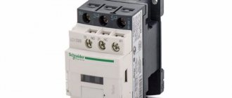
What is the difference between a contactor and a starter?
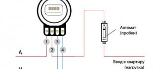
In fact, a contactor is a device consisting only of an electromagnetic coil and contacts. When voltage is applied to the coil, the contacts close (or open). The contactor does not contain devices for protection, fixation, switching, indication, etc. A starter is a device that contains a contactor as the main component element. In addition, the starter usually contains a thermal relay for protection against overcurrent, START and STOP buttons, an indication, can be enclosed in a housing, and have a circuit breaker for short-circuit protection. In other words, the starter is used to start (turn on) various electricity consumers.
More details about the purpose and design of the contactor are described in the video:
Details on how a three-phase electric motor is connected to a starter and various circuits for connecting an electric motor are given in my article on connecting asynchronous motors. And another example of using starters is in the article about the hydraulic press circuit. Various schemes for switching on magnetic starters are discussed in detail here.
And if you are at all interested in what I write about, subscribe to receive new articles and join the group on VK!
The starter may contain two or three contactors. This happens in cases where reversible engine control , or during soft start , when a powerful engine is turned on first in a star circuit and then in a delta circuit.
Although such a scheme cannot be called “smooth”, there are special devices for smooth starting. Read my articles about the Soft Starter and about the Real Circuit for Switching on a Soft Starter.
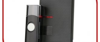
Disassembled starter PML-1220 0*2B. The contactor and thermal relay are visible.
Officially, the differences between a contactor and a starter are specified in GOST R 50030.4.1-2012
(IEC 60947-4-1:2009) Low voltage distribution and control equipment. Part 4. Contactors and starters. Section 1. Electromechanical contactors and starters.
From this GOST we can conclude that the motor protection circuit breaker, star-delta circuit, soft starter and frequency converter are also starters!
More definitions of contactors and starters are given in GOST 17703-72 “Electrical switching devices. Basic concepts” and GOST R 500030.4.4-2012 “Low-voltage distribution and control equipment”.
It will also be interesting what huge debates flared up on my Yandex.Zen channel in an article about the differences between contactors and starters.
Magnetic starters PMA series
· Rated currents: PMA-3000 - 40 A, PMA-4000 - 63 A, PMA-5000 - 100 A, PMA-6000 - 160 A.
· Coil voltage: 220—380 V; 50 Hz.
| No. | Type | Execution |
| 1. | PMA-3100 | Open, irreversible, without relay, 1P00 |
| 2. | PMA-3200 | Open, irreversible, with relay, 1P00 |
| 3. | PMA-3110 | Closed, irreversible, without relay, 1Р40 |
| 4. | PMA-3210 | Closed, irreversible, with relay, 1Р40 |
| 5. | PMA-3300 | Open, reversible, without relay, 1P00 |
| 6. | PMA-3400 | Open, reversible, with relay, 1P00 |
| 7. | PMA-3410 | Closed, reversible, with relay, 1Р40 |
| 8. | PMA-3500 | Open, reversible, without relay, 1P00 |
| 9. | PMA-4100 | Open, irreversible, without relay, 1P00 |
| 10. | PMA-4110 | Closed, irreversible, without relay, 1Р40 |
| 11. | PMA-4120 | Closed, irreversible, without relay, 1Р54 |
| 12. | PMA-4130 | Closed, irreversible, without relay, 1P40, with buttons |
| 13. | PMA-4140 | Closed, irreversible, without relay, 1P54, with buttons |
| 14. | PMA-4200 | Open, irreversible, with relay, 1P00 |
| 15. | PMA-4210 | Closed, irreversible, with relay, 1Р40 |
| 16. | PMA-4220 | Closed, irreversible, with relay, 1Р54 |
| 17. | PMA-4230 | Closed, irreversible, with relay, 1P40, with buttons |
| 18. | PMA-4240 | Closed, irreversible, with relay, 1P54, with buttons |
| 19. | PMA-4300 | Open, reversible, without relay, 1P00 |
| 20. | PMA-4310 | Closed, irreversible, without relay, 1Р40 |
| 21. | PMA-4320 | Closed, reversible, without relay, 1Р54 |
| 22. | PMA-4400 | Open, reversible, with relay, 1P00 |
| 23. | PMA-4410 | Closed, reversible, with relay, 1Р40 |
| 24. | PMA-4420 | Closed, reversible, with relay, 1Р54 |
| 25. | PMA-4500 | Open, reversible, without relay, 1P00 |
| 26. | PMA-4510 | Closed, reversible, without relay, 1Р40 |
| 27. | PMA-4520 | Closed, reversible, without relay, 1Р54 |
| 28. | PMA-4600 | Open, reversible, with relay, 1P00 |
| 29. | PMA-4610 | Closed, reversible, with relay, 1Р40 |
| 30. | PMA-4620 | Closed, reversible, with relay, 1Р54 |
| 31. | PMA-6102 | Open, non-reversible, without relay |
| 32. | PMA-6202 | Open, irreversible, with relay |
| 33. | PMA-6112 | Closed, irreversible, without relay, 1Р40 |
| 34. | PMA-6212 | Closed, irreversible, with relay, 1Р40 |
| 35. | PMA-6122 | Closed, irreversible, without relay, 1Р54 |
| 36. | PMA-6222 | Closed, irreversible, with relay, 1Р54 |
| 37. | PMA-6132 | Closed, irreversible, without relay, 1P40, with buttons |
| 38. | PMA-6232 | Closed, irreversible, with relay, 1P40, with buttons |
| 39. | PMA-6142 | Closed, irreversible, without relay, 1P54, with buttons |
| 40. | PMA-6242 | Closed, irreversible, with relay, 1P54, with buttons |
| 41. | PMA-6302 | Open, reversible, no relay |
| 42. | PMA-6402 | Open, reversible, with relay |
| 43. | PMA-6502 | Open, reversible, no relay |
| 44. | PMA-6602 | Open, reversible, with relay |
| 45. | PMA-6312 | Closed, reversible, without relay, 1Р40 |
| 46. | PMA-6412 | Closed, reversible, with relay, 1Р40 |
| 47. | PMA-6512 | Closed, reversible, without relay, 1Р40 |
| 48. | PMA-6612 | Closed, reversible, with relay, 1Р40 |
| 49. | PMA-6322 | Closed, reversible, without relay, 1Р54 |
| 50. | PMA-6422 | Closed, reversible, with relay, 1Р54 |
| 51. | PMA-6522 | Closed, reversible, without relay, 1Р54 |
| 52. | PMA-6622 | Closed, reversible, with relay, 1Р54 |
Contact attachments for PML and PM12 starters
| No. | Type | Number of contacts | No. | Type | Number of contacts |
| 1. | PKL 11M.04B | 1z+1r | 5. | PKL 40M.04B | 4z |
| 2. | PKL 22M.04B | 2z+2r | 6. | PKL 11M.04A | 1z+1r |
| 3. | PKL 04M.04B | 4p | 7. | PKL 22M.04A | 2z+2r |
| 4. | PKL 20M.04B | 2z |
Thermal and current relays
| No. | Type | Setting current, A | No. | Type | Setting current, A |
| 1. | RTT-111 | up to 25 | 14. | RTL 1010 | 3,6—6,0 |
| 2. | RTT-141 | 15. | RTL 1012 | 5,6—8,0 | |
| 3. | RTT-211 | up to 40 | 16. | RTL 1014 | 7,0—10,0 |
| 4. | RTT-311 | up to 100 | 17. | RTL 1016 | 9,5—14,0 |
| 5. | RTT-321 | up to 160 | 18. | RTL 1021 | 13,0—19,0 |
| 6. | RTL-1001 | 0,1—0,17 | 19. | RTL 1022 | 18,0—25,0 |
| 7. | RTL-1002 | 0,16—0,26 | 20. | RTL 2053 | 23,0—32,0 |
| 8. | RTL 1003 | 0,24—0,4 | 21. | RTL-2055 | 30—41 |
| 9. | RTL 1004 | 0,38—0,65 | 22. | RTL 2057 | 38,0—52,0 |
| 10. | RTL 1005 | 0,61—1,0 | 23. | RTL 2059 | 47,0—64,0 |
| 11. | RTL-1006 | 0,95—1,6 | 24. | RTL 2061 | 54,0—74,0 |
| 12. | RTL 1007 | 1,5—2,6 | 25. | RTL 2063 | 63,0—86,0 |
| 13. | RTL 1008 | 2,4—4,0 |
Electromagnetic starter PM12-016
The starters are designed for remote control of three-phase asynchronous motors with a squirrel-cage rotor with a power of up to 7.5 kW. The starters have reduced weight and dimensions, high performance parameters, allow screwless mounting on a standard P2-1 type rail using spring hooks, and provide a degree of protection of 1P20.
Rice. 1. Irreversible starter PM12-016
Rice. 2. Reversing starter PM12-016
Rice. 3. PKL contact attachment
PM12-016 starters can be used instead of imported devices for similar purposes - such as LC1-D1710 (France), 3TV 4217 (Germany), DIL OM/22 (Germany), etc.
Specifications:
| Wear resistance level | B |
| Number of additional contacts in the auxiliary circuit | 1 |
| Rated current, A | 16 |
| Accommodation category | 3 |
| Climatic performance | U |
Table 10.1. Starter characteristics
| Starter type | Current frequency, Hz | Rated voltage of switching coils, V | Degree of protection | Purpose (reversible, non-reversible) | Dimensions, mm | Weight, kg | Number and design of auxiliary circuit contacts |
| PM-12-016101 | 50 | 24—660 | 1P00 | Irreversible | 45 x 68 x 78 | 0,33 | 1r |
| 60 | 24—440 | ||||||
| PM-12-016100 | 50 | 24—660 | 1P00 | Irreversible | 45 x 68 x 78 | 0,33 | 1z |
| 60 | 24—440 | ||||||
| PM-12-016150 | 50 | 24—660 | 1Р20 | Irreversible | 45 x 68 x 78 | 0,33 | 1z |
| 60 | 24—440 | ||||||
| PM-12-016151 | 50 | 24—660 | 1Р20 | Irreversible | 45 x 68 x 78 | 0,33 | 1r |
| 60 | 24—440 | ||||||
| PM-12-016501 | 50 | 24—660 | 1P00 | Reversible | 97 x 84 x 106 | 0,71 | 2p |
| 60 | 24—440 | ||||||
| PM-12-016551 | 50 | 24—660 | 1Р20 | Reversible | 97 x 84 x 106 | 0,71 | 2p |
| 60 | 24—440 |
Table 10.2. Replacement table for starters of protection degree 1P00 and 1P20
| Starter type | Types of replacement starters | |
| irreversible | reversible | |
| PME-011M, PME-041M | ||
| PM12-016100 | PME-071M, PME-111 | |
| PM12-016101 | PME-211, | |
| PM12-016150 | PML-1100,PML-1101 | |
| PM12-016151 | PML-1160M, PML-2100 | |
| PML-1161M, PML-2101 | ||
| PM12-016501 PM12-016551 | PME-073M, PME-113 PME-213, PML-1501, PML-1561M, PML-2501 | |
Video description
How to choose a magnetic starter for an asynchronous electric motor?
Wear resistance
Each actuation of the starter wastes its operational resource. The number of inclusions, although very large, is limited. It is more profitable to buy those devices that have a sufficiently large supply. This characteristic is called switching wear resistance.
Scheme of operation of a magnetic starter Source grand-electro.ru
This parameter can correspond to one of three classes. The most wear-resistant is class “A”. It implies from 1.5 to 4 million equipment activations. If the user prefers “B”, then there will be from 630 to 1500 of them, and for “C” - from 100 to 500 thousand times.
Mechanical resistance to wear is considered separately. It indicates the number of times the device was turned on until the device needed to be repaired and its parts replaced. This number should be determined on the condition that they are carried out without electrical load. This characteristic in most cases is 3-20 million.
Magnetic starter series PML Source grand-electro.ru
Number of poles and contacts
For three-phase devices, three poles must be used when switching on. This configuration is the most common. However, in some cases it is necessary to use only two. An example of such situations is working with lighting devices.
In addition to the working contacts that are connected to the controlled equipment, the devices can be equipped with additional ones that operate in parallel with the main ones. Typically, they are designed to perform actions such as blocking, powering lamps that perform a signal function, and similar. A sufficiently large quantity allows for high functionality of the starter.
Normally open auxiliary contacts are switched off when de-energized. In order to activate them, it is necessary to start the equipment. There is also another type. In the non-working position they are connected. At the beginning of the starter operation they open. They are called normally closed.
Reversing magnetic starter Source poligon.info
10.1. PKL contact attachment for PM12 starters
The PKL contact attachment is installed on a magnetic starter and serves to increase the number of its auxiliary contacts.
Specifications:
| Wear resistance level | B |
| Climatic performance | ABOUT |
| Accommodation category | 4 |
| Degree of protection | 1Р20 |
Table 10.1.1. Characteristics of the contact PCL attachment
| Set-top box type | Number of normally open contacts | Number of normally closed contacts | Dimensions, mm | Weight, kg |
| PKL 22M04B | 2 | 2 | 44 x 47 x 36 | 0,055 |
| PKL 20M04B | 2 | — | 25.5 x 47 x 36 | 0,03 |
| PKL 04M04B | — | 4 | 44 x 47 x 36 | 0,055 |
| PKL 40M04B | 4 | — | 44 x 47 x 36 | 0,055 |
| PKL 11M04B | 1 | 1 | 25.5 x 47 x 36 | 0,03 |
Types of starters by purpose
Now I will give a couple of examples of starters - real circuits.
This starter circuit is assembled on three second-value contactors and is used to connect an electric motor according to a star-delta circuit. At the top left three phases are supplied, at the bottom three phases go to power the motor. Red wires – powering the contactor coils and checking operation. Protection (automatic motor) is not shown.
reversing starter with automatic motor
Here is a reversing starter, with two mutually interlocked contactors. Automatic engine protection motor - on the right.
10.2. Electromagnetic current relays RTT5-16 for PM12 starters
The relay is designed to protect three-phase asynchronous electric motors with a squirrel-cage rotor from current overloads of unacceptable duration, including when one of the phases fails. The relay is attached directly to the PM12-016 starter or individually on a standard rail using a KP5 terminal block.
Specifications:
| Rated current, A | 16 |
| Rated current in auxiliary contacts, A | 6,3 |
| Power consumed by one current circuit, W | 2,1 |
| Response time, s: · from a cold state; from a heated state | 4—8 0,8 |
| Climatic performance | U |
| Accommodation category | 3 |
| Dimensions, mm | 44 x 55.5 x 88 |
| Weight, kg | 0,12 |
Magnetic starters. General information
| • Starters • |
- General information
- Magnetic starters PME series
- Magnetic starters PML series
- Magnetic starters PMS series
- Magnetic starters PMA series
- Magnetic starters of the PA and PAE series
- Magnetic starters PM12 series
- Magnetic starters series P6-100
- Adjusting contacts of starters
- Checking the magnetic starter system
- Maintenance of magnetic starters
- Terminology
- …
| • Site overview • |
- Electrical equipment up to 1000 V
- Electrical apparatus
- Electric cars
- Operation of electrical equipment
- Electrical equipment of electrical technological installations
- Electrical equipment for general industrial installations
- Electrical equipment for lifting and transport installations
- Electrical equipment of metalworking machines
- Electrical equipment above 1000 V
- High voltage electrical apparatus
- Electrical engineering
- Electric field
- DC electrical circuits
- Electromagnetism
- DC Electrical Machines
- Basic concepts related to alternating currents
- AC circuits
- Three-phase circuits
- Electrical measurements and instruments
- Transformers
- AC Electrical Machines
- Electrical installation
- Where does electrical installation of power supply of electrical equipment and wiring begin?
- Electrical wiring installation
- Calculation of power consumption, cable cross-section and circuit breaker rating
- Electrical installation work and cable laying in residential and non-residential premises
- Electrical installation work on disconnecting junction boxes and electrical equipment
- Electrical installation and grounding of sockets
- Electrical installation of potential equalization
- Electrical installation of the ground loop
- Electrical installation of a modular pin ground loop
- Electrical installation of heating cable for underfloor heating
- Electrical installation work on laying cables in the ground
- Electricity in a private house
- Power supply project
| • Electrical equipment • |
- Electrical equipment up to 1000 V
- Electrical apparatus
- Electric cars
- Operation of electrical equipment
- Electrical equipment of electrical technological installations
- Electrical equipment for general industrial installations
- Electrical equipment for lifting and transport installations
- Electrical equipment of metalworking machines
- Electrical equipment above 1000 V
- High voltage electrical apparatus
ELECTROSPETS
ELECTROSPETS
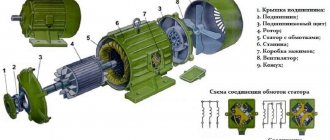
A magnetic starter is a combined remote control device, consisting of a contactor supplemented by a thermal relay, and combining the functions of control and protection devices. As a control device it is used, for example, to start, stop and change (reverse) the direction of rotation of an electric motor and switch the windings of a three-phase motor from “star” to “delta” to reduce the starting current of the motor, and as a protection device they turn off the electric motor or electrical installation when unacceptable overloads and short circuits, as well as during a certain decrease or complete disappearance of voltage (zero protection).
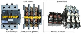
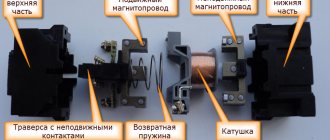
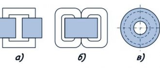
Design of a magnetic starter Magnetic starters have a magnetic system consisting of an armature and a core and enclosed in a plastic case. A retractor coil is placed on the core. A traverse slides along the guides of the upper part of the starter, on which the armature of the magnetic system and bridges of power (main) and blocking contacts with springs are assembled. Power ones are used to switch powerful loads; block contacts are in the control circuit. Power and block contacts can be normally open (Normal Open, NO) and normally closed (Normal Close, NC). The normally open contact is open in the normal position of the contactor. The normally closed contact is closed in the normal position of the contactor. The starter contacts on the circuit diagrams are shown in their normal position. A reversible magnetic starter consists of two three-pole contactors mounted on a common base and interlocked with a mechanical or electrical interlock, which eliminates the possibility of simultaneous activation of the contactors.
The principle of operation of a magnetic starter When voltage is applied to the coil, the armature is attracted to the core, the normally open contacts close, and the normally closed contacts open. When the starter is turned off, the opposite picture occurs: under the action of return springs, the moving parts return to their original position, while the main contacts and normally open block contacts open, and normally closed block contacts close.
Categories of application of magnetic starters. AC-1 – starter load is active or low inductive. AC-3 – direct start mode of an electric motor with a squirrel-cage rotor, turning off a rotating motor. AC-4 – starting an electric motor with a squirrel-cage rotor, turning off stationary or slowly rotating engines, countercurrent braking.
Standardized technical characteristics: • Maximum permissible current of the main circuit in amperes. It is normalized for the operating mode of the starter AC-1, AC-3 or AC-4 separately for each of the main circuit voltage values, i.e. starter operating voltage; • Maximum permissible main circuit voltage (V); • Retractor coil supply voltage (V). Can be selected from a range of 24, 36, 42, 110, 220, 380V AC. Some types of starters are manufactured with a magnetic system powered by a DC control coil, and they are connected to the AC circuit through a rectifier; • Electrical wear resistance. Calculated in millions of on-off cycles. To determine the switching wear resistance, it is necessary to set the operating mode of the starter, the voltage of the main circuit, the current of the main circuit (or the power of the controlled motor) and, according to the corresponding nomogram given in the technical description of the starter, determine the guaranteed number of on-off times. It is necessary to take into account that the operating mode of the starter takes into account the frequency of its on-off times per hour; • Maximum permissible current of auxiliary contacts. Calculated in amperes at a given voltage on the contacts; • Power consumed by the retractor coil (indicated in watts) As an element of automatic control systems, electromagnetic starters are subject to high wear resistance requirements. Wear resistance classes: A, B and C. Starters are produced in versions with varying degrees of protection against contact and external influences (IP00, IP20, IP40, IP54). Climatic modification and placement categories according to GOST 15150-69 and GOST 15543.1-89.
Thus, the reliable operation of the starter is determined by a number of factors that must be correctly assessed at the stage of its selection. When selecting a starter, the term “starter size” is widely used. This term is conditional and characterizes the permissible current of the contacts of the main circuit of the starter. This assumes that the main circuit voltage is 380V and the starter operates in AC-3 mode.
The maximum main circuit current is:
■ for a zero-value starter - 3 A, 4 A; ■ for a starter of the first magnitude - 10 A; ■ for a starter of the second size - 25 A; ■ for a starter of the third value - 40 A; ■ for a fourth-value starter - 63 A, 80 A; ■ for a fifth-size starter – 100A, 125 A; ■ for a sixth-size starter—160 A; ■ for a starter of the seventh value - 250 A.
The permissible current of the main circuit contacts differs from those given above depending on: • On the application category - AC-1, AC-3 or AC-4 With an increase in the number of the application category, the permissible current of the main circuit contacts, with equal parameters for switching wear resistance, decreases; • From the voltage on the main circuit contacts. As the voltage increases, the permissible current of the contacts decreases. For some types of starters, the starter size is indicated at a main contact voltage other than 380V.
the PME and PAE series were most widespread . Starters of the PME series are used to control electric motors with a power from 0.27 to 10 kW, and starters of the PAE series are used to control electric motors and other electrical installations with a power of 4 to 75 kW. Currently, the modification of starters has expanded significantly.
An example of the structure of the symbol for magnetic starters of the PME series
PME X1 X2 X3
X1 - starter value - 1, 2nd
X2 - version of starters according to the degree of protection and the presence of control buttons and a signal lamp
- 1 - IP00
- 2 — IP30
- 2 — IP54
X3 - type of electric motor operation and the presence of a thermal relay
- 1 — without thermal relay, irreversible
- 2 — with thermal relay, irreversible
- 3 — without thermal relay, reversible
- 4 — with thermal relay, reversible
Thermal relays TRN (double-pole) and TRP (single-pole), thermal relays of the RTT and RTL . They are triggered under the influence of the motor overload current flowing through them and disconnect it from the network.
When turning on the NO starter, the contact block must have a lag from the main contacts of at least 0.5 mm (i.e., the contact block opening must be 0.5 mm greater than the main contact opening, and the gap must be 0.5 mm less).
When using a NC block of contacts in a starter and when turning on the starter, they must open before the main contacts close by at least 0.5 mm.
The main contacts of the starters do not require special care and lubrication. After significant wear, the contacts must be replaced. When sagging forms, the contact surface should be filed with a velvet file.
During repairs, it is necessary to pay attention to the size of the openings, dips and pressures of the main contacts and the contact block.
in the main contacts of magnetic starters must comply with the manufacturer's instructions.
The magnitude of the dip is determined by removing the fixed contact and measuring the amount of movement of the movable contact or by measuring the gap, which characterizes the dip between the movable contact and its stop in the on position of the contact.
The deflection of the damping springs of fixed contacts and block contacts when switched on should be 1-1.5 mm.
The non-simultaneous contact of the main contacts in three phases when switching on should not exceed 0.5 mm.
The insulation resistance of magnetic starters must be at least 0.5 MOhm. The magnetic starter casing must be grounded.
The initial pressing of the contacts is selectively checked. To check it is necessary: 1) to outline the line of contact between the contacts; 2) install the armature of the magnetic system so that the contacts are open; 3) place a strip of tissue paper between the movable contact and the plate (bracket) on which the movable contact is installed; 4) place a loop of keeper tape on the movable contact along the line of contact and hook it. dynamometer hook; 5) pull back the dynamometer, making sure that the tension line is perpendicular to the plane of contact of the contactors. The amount of pressure applied to the contactor must correspond to the manufacturer's specifications. A small pressure on the contacts results in their overheating, while a large pressure prevents the starter from turning on.
Magnetic starters are mounted vertically; the deviation from the vertical should not exceed 5 o .
Magnetic starters are not designed to interrupt short circuit currents. These currents should break the circuit breakers or fuses installed on the supply lines.
In properly adjusted magnetic starters and contactors, a slight hum from the magnetic system is allowed when turned on. Strong humming may be the result of: poor tightening of the screws securing the core; the presence of a short-circuited turn; excessive contact pressure; loose fit of the armature to the core due to contamination of the contact surfaces. Mechanical interlocking of contactors, reversing starters, etc. should not interfere with the free and complete switching on of each of the interlocked devices.
10.3. Electromagnetic current relay RTT5-16
Rice. 4. Electromagnetic current relays RTT5-16
Table 10.3.1. Relay with one changeover contact with manual reset and switchover to self-reset
| Name | Non-operation current regulation range, A |
| RTT5-16-012U3 | 0,10—0,15 |
| RTT5-16-022U3 | 0,14—0,21 |
| RTT5-16-032U3 | 0,20—0,30 |
| RTT5-16-042U3 | 0,28—0,40 |
| RTT5-16-052U3 | 0,38—0,54 |
| RTT5-16-062U3 | 0,52—0,75 |
| RTT5-16-072U3 | 0,70—1,00 |
| RTT5-16-082U3 | 0,95—1,40 |
| RTT5-16-092U3 | 1,30—1,9 |
| RTT5-16-102U3 | 1,80—2,6 |
| RTT5-16-112U3 | 2,50—3,6 |
| RTT5-16-122U3 | 3,30—4,8 |
| RTT5-16-132U3 | 4,20—6,0 |
| RTT5-16-142U3 | 5,50—8,0 |
| RTT5-16-152U3 | 7,00—10,0 |
| RTT5-16-162U3 | 9,5—14,0 |
| RTT5-16-172U3 | 13,0—16,0 |
Table 10.3.2. Relay with one normally closed contact and manual reset
| Name | Non-operation current regulation range, A |
| RTT5-16-011U3 | 0,10—0,15 |
| RTT5-16-021U3 | 0,14—0,21 |
| RTT5-16-031U3 | 0,20—0,30 |
| RTT5-16-041U3 | 0,28—0,40 |
| RTT5-16-051U3 | 0,38—0,54 |
| RTT5-16-061U3 | 0,52—0,75 |
| RTT5-16-071U3 | 0,70—1,00 |
| RTT5-16-081U3 | 0,95—1,40 |
| RTT5-16-091U3 | 1,3—1,9 |
| RTT5-16-101U3 | 1,8—2,6 |
| RTT5-16-111U3 | 2,5—3,6 |
| RTT5-16-121U3 | 3,3—4,8 |
| RTT5-16-131U3 | 4,2—6,0 |
| RTT5-16-141U3 | 5,5—8,0 |
| RTT5-16-151U3 | 7,0—10,0 |
| RTT5-16-161U3 | 9,5—14,0 |
| RTT5-16-171U3 | 13,0—16,0 |
Differences between a relay and a contactor
Relays differ from contactors only in design and purpose, and the difference between them is sometimes barely distinguishable.
Usually,
- The relay does not have arc chutes.
- The relay is housed in a sealed housing.
- The relay is designed for low current and purely resistive loads.
- The relay has switching contacts, which means normally open and closed.
- The relay is not designed to connect a reactive three-phase load.
- A relay can have from 1 to 6 equivalent contacts, and a contactor must have 3 power and (as an option) 1-2 low-current contacts.
- The relay does not have additional functions or contacts, and the contactor can be supplemented with attachments for various installations and purposes.
- The relay is mounted on the panel and can be easily replaced using just your hands. In order to replace the contactor, you need to de-energize the equipment and use a screwdriver.
Learn more about what a relay is and what it is needed for in the video:
Modular contactors
Intended for use for automatic control of consumers such as a small pump, fans, heating or lighting systems.
The series consists of a number of devices that differ in the number of working contacts, the switching power of the contacts and the value of the supply voltage of the excitation coil.
Version: stationary (DIN rail mounting).
Table 11.1. Modular contactors AC and ESB series
| Options | Unit | 230 AC | 400 AC | 400 AC | 400 AC |
| Rated current In, at AC-1 | A | 20 | 24 | 40 | 63 |
| Rated power at AC-1: | |||||
| · 230 V | kW | 1,3 | 2,2 | 5,5 | 8,5 |
| · 400 V | 4 | 6,5? | 11 | 15 | |
| Rated frequency | Hz | 50/60 | 50/60 | 50/60 | 50/60 |
| Control voltage | IN | 12, 24, 48, 110, 230 | 12, 24, 230 | 24, 230 | 24, 230 |
| Mechanical wear resistance (on/off) | Cycles (on/off) | 1000000 | 1000000 | 1000000 | 1000000 |
| Electrical durability (on/off): | Cycles (on/off) | ||||
| · at AC-1 | 150000 | 130000 | 150000 | 150000 | |
| · at AC-3 | 150000 | 500000 | 170000 | 240000 | |
| Power dissipation | W | 1 per pole | 1, 2 per pole | 3 | 6 |
| Number of modules | things | 1 | 2 | 3 | 3 |
Accessories
For modular contactors of the AC and ESB series, a contact attachment is available that has 1no+1no or 2no auxiliary contacts.
Rice. 5. Modular contactors
Distinctive features of contactors and magnetic starters
Contactors and magnetic starters are electrical devices that are important components of electrical networks. They are intended for communication between power-type circuits and control circuits. Often, equipment adjustment specialists cannot always give a substantiated answer as to how a contactor differs from a magnetic starter. Both perform a list of similar purposes, but still there are differences between them, since each of them has its own unique functions and features.
A series contactors
Designed to control medium power consumers (current from 9 to 110 A). Version: stationary (mounting on a circuit board).
Table 12.1. A series motor contactors
| Type | Engine power | Rated operating current | |
| AC-3 | AC-1 | ||
| A9-30-10 | 4 kW | 9 A | 25 A |
| A12-30-10 | 5.5 kW | 12 A | 27 A |
| A16-30-10 | 7.5 kW | 16 A | 30 A |
| A26-30-10 | 11 kW | 26 A | 45 A |
| A30-30-10 | 15 kW | 32 A | 55 A |
| A40-30-10 | 18.5 kW | 37 A | 60 A |
| A50-30-10 | 22 kW | 50 A | 100 A |
| A63-30-10 | 30 kW | 63 A | 115 A |
| A75-30-10 | 37 kW | 75 A | 125 A |
| A95-30-10 | 45 kW | 96 A | 145 A |
| A110-30-10 | 55 kW | 110 A | 160 A |
Rice. 6. A series motor contactors
Rice. 7. Overload thermal relays
Table 12.2. Overload thermal relays
| Contactor | Thermal relay | Current setting range |
| A9-30-10 A12-30-10 | TA25DU | 0,1¸0,16; 0,63¸1,0; 2,2¸3,1; 6,0¸8,5; 0,16¸0,25; 1,0¸1,4; 2,8¸4,0; 7,5¸11; 0,25¸0,40; 1,3¸1,8; 3.5¸5.0; 10¸14; 0.40е0.63; 1.7¸2.4; 4.5¸6.5; 13¸19; 18¸25; 24¸32 |
| A16-30-10 | ||
| A26-30-10 A30-30-10 | TA42DU | 18¸25; 22 ¸32; 29 ¸42 |
| A40-30-10 | ||
| A50-30-10 | ||
| A63-30-10 | TA75DU | 18¸25; 24¸32; 29¸42; 36¸52; 45¸63; 60¸80 |
| A75-30-10 | ||
| A95-30-10 | TA80DU | 29¸42; 36¸52; 45¸63; 60¸80 |
| A110-30-10 | TA110DU | 65¸90; 80¸110 |
Auxiliary contacts
Front fastening - 1no or 1nz. Lateral fastening - 1no + 1nc.
Rice. 8. Auxiliary contacts
Rice. 9. Time relay blocks (pneumatic)
Characteristics and types of starters by characteristics
Before choosing a contactor, you need to decide on the load, and make the choice based primarily on the load power. The parameters of contactors can be clarified on the manufacturers’ websites or from trading organizations, but here we will present and consider the most important ones. The main parameters (current, load power) are usually indicated on the starter housing.
Size (conditional dimensions) of the starter (contactor)
The most important parameter, the value characterizes the power and dimensions of the starter. There are the following starter sizes:
- zero value – for a maximum current of up to 6 A (through each working contact)
- the first - for a maximum current of up to 9 - 18 A (depending on the design of the contacts)
- starter 2 sizes – up to 25 – 32 A
- starter 3 sizes – up to 40 – 50 A
- starter 4 sizes – up to 65 – 95 A
- 5th size starter – up to 100 – 160 A
- sixth value – from 160 A and above
This means the current for application category AC-3 (for an inductive load), for category AC-1 (resistive or low-inductive load - for example, heating elements) the maximum current for the same starter will be one and a half to two times higher. The size of the starter determines how much power it can switch (three-phase circuit 380 V, inductive load).
- 1 – up to 2.2 – 7.5 kW
- 2 – up to 11 – 15 kW
- 3 – up to 18 – 22 kW
- 4 – up to 30 – 45 kW
12.3. Time relay blocks (pneumatic)
| Contactor | Relay | Delay range |
| A9-30-10 | TP 40 DA | with pneumatic attraction delay: · 0.1¸40 s · 10¸180 s |
| A12-30-10 | TP 180 DA | |
| A16-30-10 | ||
| with pneumatic fall-off delay: · 0.1¸40 s · 10¸180 s | ||
| A26-30-10 | ||
| A30-30-10 | ||
| A40-30-10 A50-30-10 | TP 40 IA | |
| A60-30-10 | ||
| A75-30-10 |
Locking devices
These devices are used to mechanically and electrically block the simultaneous operation of two contactors.
Rice. 10. Ve5 blocking devices
Necessary actions when operating contactors and magnetic starters
- Before installing the devices, it is necessary to remove grease from the working surfaces and check the condition of each electrical connection and check that the devices are adjusted correctly.
- It is necessary to regularly check the condition of the contact group, periodically inspecting it after 50,000 operations or after each power outage in emergency mode.
- When cleaning the surface of contacts, the main thing is to maintain their original shape.
- Check the location of the breaking contacts relative to each other. Copy paper will help.
- For contactors with several poles, the simultaneous closure of the contacts of all poles is checked.
- It is necessary to check the serviceability of the mechanical interlock.
- Constantly check the gap between the contacts. They are replaced when the original thickness is reduced by 50%, and for contacts with overlays by 80%.
Newly installed contacts must touch along a line whose total length is equal to 75% or more of the width of the moving contact. Contact displacement is allowed, no more than 1 mm in width.
Contactors EH
Designed to control powerful consumers (current from 145 to 800 A).
Version: stationary (mounting on a circuit board).
Table 13.1. EH series motor contactors
| Type | Engine power, kW | Rated operating current, A | Number of cycles (millions) |
| EH 145 | 75 | 145 | 10 |
| EH 175 | 90 | 185 | 10 |
| EH 210 | 110 | 210 | 10 |
| EH 260 | 140 | 260 | 10 |
| EH 300 | 160 | 305 | 10 |
| EH 370 | 200 | 400 | 5 |
| EH 550 | 280 | 550 | 5 |
| EH 700 | 370 | 700 | 5 |
| EH 800 | 400 | 720 | 5 |
Rice. 11. EH series motor contactors
Table 13.2. Overload thermal relays
| Thermal relay | Contactors | Current setting range, A |
| T 200 DU | EH 145 EH 175 EH 210 | 80¸200 |
| T 450 DU | EH 175 EH 210 EH 260 EH 300 EH 370 | 130¸400 |
| T 900 DU | EH 370 EH 550 EH 700 EH 800 | 265¸850 |
Table 13.3. Time relay blocks (pneumatic)
| Contactor | Relay | Delay range |
| EH 175¸EH 800 | TP 40 D TP 180 D | with pneumatic attraction delay (blue handle) · 0.1¸40 s · 10¸180 s |
| TP 40 I TP 40 I | with pneumatic drop-off delay (black handle) · 0.1¸40 s · 10¸180 s |