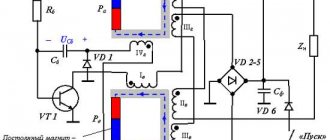
Article "Real" perpetual motion machine. Will we ever be able to build it? caused heated discussion. In the heat of debate, John Searle's invention was mentioned more than once, so N&T, briefly, I decided to describe his fuel-free generator.
The Searle generator operates on the basis of a balanced magnetic system; it can be used as a source for generating electricity at home. Despite the fact that the first generator design was developed by a scientist back in 1946, there are no publications about it in scientific journals.
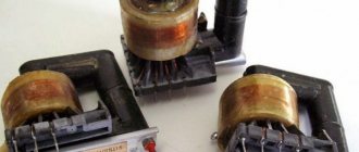
Northrop B-2A Spirit stealth strategic bombers at the 509th Whiteman Wing base in Missouri Photo: https://www.taringa.net/posts/imagenes/18143532/Northrop-Grumman-B-2-Spirit-Mix-de -fotos.html
Making a wind generator using neodymium magnets
An axial wind generator that runs on neodymium magnets was first mass produced in Western countries. And these were not factory products at all, but the fruit of the labor of local garage craftsmen who put the phenomenon of levitation into their service. These windmill models owe their serious popularity to the mass distribution and low cost of neodymium magnets. Gradually, components and steel manufacturing schemes will spread throughout the world and currently the magnetic axial wind generator is gaining recognition throughout the Russian Federation. Below is the sequence of creating one of the most successful models of such a windmill.
A couple of tips for installing a tower under a wind turbine
It is quite difficult to assemble an axial generator with your own hands. Therefore, it would be a shame if this rather heavy structure collapses to the ground at the first gust of wind. To prevent this from happening, you need to do the following:
- make a metal mount for raising and lowering the windmill;
- dig a hole and install a homemade mount;
- fill the structure with concrete;
- attach the wind generator to one end of a 6-meter pipe;
- raise the mast and secure it with spacers.
In the vast majority of cases, making a mast lower than 6 meters does not make sense, since only at such a height, almost throughout the entire territory of Russia, winds regularly circulate, the strength of which will be sufficient for the effective operation of the windmill.
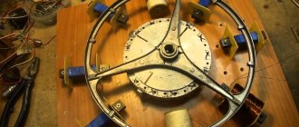
Rotor creation process
The author of the development decided to make the basis of the generator a car hub with brake discs, since it is powerful, reliable and perfectly balanced. When you start making a windmill with your own hands, you should first prepare the base for the rotor - the hub - and clean it of dirt, paint and grease. Then start gluing the permanent magnets. To create this wind generator, twenty of them were used on a disk. The size of the neodymium magnets was 25x8 millimeters. However, both their number and their size can vary depending on the goals and objectives of the person creating the wind generator with his own hands. However, to obtain one phase it will always be correct to equalize the number of poles to the number of neodymium magnets, and for three phases to maintain the ratio of poles and coils - two to three or three to four.
The magnets should be positioned taking into account the alternation of poles, and as accurately as possible, but before you start sticking them, you need to either create a paper template or draw lines dividing the disk into sectors. To avoid mixing up the poles, we make marks on the magnets. The main thing is to fulfill the following requirement: those magnets that stand opposite each other must be turned with different poles, that is, attract each other.
The magnets are glued to the disks using super glue and filled in. You also need to make borders along the edges of the disks and in their center, either by wrapping tape or molding them from plasticine to prevent spreading.
How to agree on the parameters of functional parts
The energy potential of the blades must correspond to a specific asynchronous motor or a self-assembled rotor with magnets. In case of significant deviations, in order to obtain sufficient electrical power, it will be necessary to create new products with the required parameters. The reverse situation is also unacceptable. Too large blades are not able to rotate quickly. Strong winds increase the risk of destruction of such structures.
To avoid mistakes, make a table with equipment operating modes at different rotation speeds in increments of 50-100 rpm. Next, they use specialized calculators that, based on the given values, calculate the geometric parameters of the screw. These products are created from suitable wood, metal, and plastic. Standard polyvinyl chloride pipes for external sewer networks are suitable as blanks.
Phases - which is better - three or one?
Many lovers of electrical equipment follow the path of least resistance and, in order not to bother, opt for a single-phase stator for a windmill. However, it has one unpleasant feature that neutralizes the ease of assembly - vibration when loaded, due to the variability of current output. After all, the amplitude of such a stator is abrupt, reaching a maximum when neodymium magnets are located above the coils, and then dropping to a minimum.
But when the generator is made using a three-phase system, there are no vibrations, and the power indicator of the windmill has a constant value. The reason for this difference is that the current, falling in one phase, at the same time increases in the other. As a result, a wind generator operating in a three-phase system can be up to 50% more efficient than the exact same one using a single-phase system. And most importantly, a loaded three-phase generator does not produce vibration, therefore, the mast does not give rise to complaints about the wind generator to the supervisory authorities from ill-wishers among neighbors, since it does not create an annoying hum.
Principle of operation
The operation of the generator is hybrid in the system. Alternating current is obtained after converting kinetic energy. The rotor rotates due to the force of the magnetic field that comes from the ends of the electromagnets. Thus, magnetic vibrations make it possible to create an electrical impulse. The simplest design contains:
- Generator. This is a cylindrical container that must be hermetically sealed. An electromagnetic field arises inside due to the directed action of the coils.
- Convector-converter. Produces electricity from magnetic pulses. The output is alternating current.
- Batteries. Necessary for accumulating charge. Thanks to them, you can use electricity at any time.
The main element in the design is a multi-pole direct rotation generator. There are magnets on the outside. Their number depends on the required power. The minimum efficiency of such a device is 90%. From generators, you can create electrical networks by connecting several devices to each other. This is beneficial if the power of the device is, for example, 5 kilowatts, but the required power is 10 kilowatts.
Winding method for windmill stator coil
In order for a do-it-yourself wind generator on neodymium magnets to work with maximum efficiency, the stator coils should be calculated. However, most craftsmen prefer to do them by eye. For example, a low-speed generator capable of charging a 12 V battery starting from 100 - 150 rpm should have from 1000 to 1200 turns in all coils, equally divided between all coils. An increase in the number of poles leads to an increase in the frequency of the current in the coils, due to which the generator, even at low speeds, produces more power.
The coils should be wound with thicker wires if possible in order to reduce the resistance in them. This can be done on a mandrel or on a homemade machine.
In order to figure out what power potential the generator has, spin it with one coil, since, depending on how many neodymium magnets are installed and what their thickness is, this indicator may differ significantly. The measurements are carried out without load at the required number of revolutions. For example, if a generator at 200 rpm provides a voltage of 30 V, having a resistance of 3 ohms, then subtract 12 V (battery supply voltage) from 30 V and the resulting result is 18 divided by 3 (resistance in ohms) we get 6 ( current in amperes), which will go from the wind generator to charge the battery. However, as practice shows, due to losses in the wires and diode bridge, the actual indicator that the magnetic axial generator will produce will be less.
It is better to take magnets for creating a wind generator in the shape of a rectangle, since their field extends along the length, unlike round ones, the field of which is concentrated in the center. Coils are usually wound round, although it is better to make them somewhat elongated, which provides a larger volume of copper in the sector, as well as straighter turns. The hole inside the coils must be equal to or greater than the width of the magnets.
The thickness of the stator should be the same as the magnets. The form for it is usually plywood; for strength, fiberglass is placed under the coils and on top of them, and the whole thing is filled with epoxy resin. In order to prevent the resin from sticking to the mold, the latter is lubricated with any fat or adhesive tape is used. The wires are first brought out and fastened together, the ends of each phase are then connected with a triangle or an asterisk.
Stator assembly
To begin with, I had to create a mold from plywood with a lid and bolts in the “ears” of the stator for casting the main part of my homemade product. Then I proceeded according to the following scheme:
- laid fiberglass on the bottom of the mold;
- I treated everything with Vaseline;
- laid out the coils and brought the ends of the wires outside the mold;
- poured epoxy with talc filler;
- covered the coils on top with a layer of fiberglass;
- I closed the mold with a lid and tightened the bolts, making a kind of press.
Attention! The thickness of the stator should be equal to the thickness of the magnets used to create the windmill.
Source e-veterok.ru
After the epoxy resin had hardened, I disassembled the mold, made sure there were no cracks, soldered the ends of the coils with an asterisk and began the final assembly of the structure. At the end of the work, tests were carried out, during which it turned out that the homemade generator, even when rotated manually, produces a voltage of up to 40 V with a current of up to 10 A.
How to increase the power of a windmill?
Magnets can be used to increase the power of a wind generator. Simply stick one more of the same or thinner magnets on the magnets that are already installed. Another method is based on installing metal cores, called transformer plates, into coils. This will ensure increased magnetic flux in the coil, but causes slight sticking, which, however, is not felt at all by the six-blade propeller. Such a wind generator starts at a wind of 2 m/s. Thanks to the use of cores, the generator received an increase in power from 300 to 500 W/h with a wind of 8 m/s. You should also pay attention to the shape of the blades - the slightest inaccuracies reduce power.
Axial generator with ferrite magnets
Probably many people are interested in the possibility of using alternative energy. The author of this device is one of these, he also read various articles on the Internet devoted to renewable energy sources. He was especially interested in the use of wind energy, since in his area the winds are quite strong and he immediately realized that a properly designed wind generator would produce a fairly large amount of energy.
Having become familiar with the main types of windmills and the generators used in them, the author settled on an axial generator with ferrite magnets.
Materials that were used by the author to create this generator:
1) metal pipe 2) bearings 3) pin 4) diamond discs with a diameter of 22 cm 5) 40 ferrite magnets 6) epoxy resin 7) wire 0.5 mm thick metal angle 9) screwdriver 10) plywood 11) jigsaw
Let us consider in more detail the design of this generator model, as well as the main stages of its assembly.
This generator was built completely from scratch. Its basis was a hub, which the author assembled himself from a piece of pipe. Bearings and a pin were installed in this pipe. Having welded several sections of a corner to this pipe, the author received a ready-made base for attaching the stator of the future generator of his windmill.
Hub, and corners for mounting the stator, markings before welding
The author decided to use diamond discs with a diameter of about 220 mm as generator rotors. In order to accurately mount all the ferrite magnets on them, the author laid them out in such a way that there were twenty identical sectors, at the joints of which the magnets were placed. In order for the magnets to be securely attached to the disks, the author used super glue and epoxy resin: first, the magnets were fixed with a drop of super glue and then filled with epoxy resin.
Installing magnets on rotor disks:
This is approximately how the rotor disks will stand:
The author needed this frame in order to more easily and conveniently wind 15 coils of wires. This is the number of coils the author decided to use to create a stator. The winding device was put on the screwdriver, after which it was turned on and the author wound 325 turns of wire 0.5 mm thick. The author explains such a large number of turns of wire for the coils by the fact that the ferrite magnets used to create the generator are quite weak. The final thickness of the coils was 9 mm. Therefore, measurements of the resistance of one phase showed a value of 18.5 Ohms, which, of course, is not the best indicator for building a generator, but thanks to this design of the coils, the voltage will be within normal limits and suitable for charging batteries.
Finished stator coils, wire 0.5 mm, 325 turns, thickness 9 mm:
After the coils were completely ready, the author decided to begin manufacturing a stator based on them. To begin with, the author took a sheet of plywood and cut out the necessary shape for the stator. The author plans to place the coils in this form and fill them with epoxy resin. To make it easier to separate the stator from the mold, the author covered the plywood blank with tape. After that, all six wires from the phases were connected together and everything was filled with epoxy resin.
Stator coils before filling with epoxy resin:
A mold for casting a stator, a template with a film underneath, the edges of the mold are covered with tape:
When the mold hardened, the author separated it from the workpiece and obtained a finished stator. The next step was to assemble all the parts of the generator together and test it manually. Thus, when connected in a triangle and spinning the generator by hand, the short circuit current was about 1.5 amperes and the voltage was 15 volts. The author also tested the generator using a screwdriver. For this purpose, the screwdriver was specially connected to the generator and the author managed to spin it up to 700 rpm and get a voltage of 47 volts.
Finished axial generator stator:
General view of the finished generator for a windmill
Then the author began to assemble and select a suitable screw for this generator model. Several screws were made from PVC pipe with a diameter of 110 mm. However, such propellers did not give the necessary results, since they were too slow and did not develop the required speeds for full operation of the generator.
Generator with propeller before installation on the mast:
Making a screw
I cut the blades for the propeller from a PVC pipe with a diameter of 160 mm according to drawings that I found on the Internet. At the same time, you need to understand that the slightest inaccuracy will instantly affect the efficiency of the entire structure. Personally, I chose a 5-blade design, but a three-blade option will also be effective, especially in areas with strong winds.
Source findpatent.ru
Homemade generator for a windmill
How to make a low-speed generator for a windmill from neodymium magnets. Homemade generator for a windmill, diagrams, photos, videos.
To make a homemade windmill, you first need a generator, preferably a low-speed one. This is the main problem; finding such a generator is quite difficult. The first thing that comes to mind is to take a standard car generator, but all car generators are designed for high speeds, battery charging starts at 1000 rpm. If you install a self-generator on a windmill, it will be difficult to achieve such speeds; you will need to make an additional pulley with a belt or chain drive, all this complicates and makes the design heavier.
A windmill requires a low-speed generator; the best option is an axial type generator with neodymium magnets. Since there are practically no such generators on sale at an affordable price, you can make an axial generator yourself.
Homemade generator for a windmill made from neodymium magnets.
To make an axial type generator you will need:
- Car hub, brake discs.
- Neodymium magnets.
- Copper wire (0.7mm).
- Epoxy resin.
- Fastening elements.
An axial type generator for a windmill is shown in the diagram.
In this case, the stator will be a disk with coils, the rotor will be two disks with permanent magnets. When the rotor rotates, the current that we need to charge the batteries will be generated in the stator coils.
Homemade generator: making a stator.
The stator - the stationary part of the generator consists of coils that are placed opposite the rotor magnets. The internal size of the coils is usually equal to the external size of the magnets that are used in the rotor.
A simple device can be made for winding coils.
The thickness of the copper wire for the coils is approximately 0.7 mm, the number of turns in the coils must be counted individually, the total number of turns in all coils must be at least 1200.
The coils are placed on the stator; the coil terminals can be connected in two ways, depending on how many phases the generator will have.
A three-phase generator will be more efficient for a wind generator, so it is recommended to connect the coils in a star type.
To fix the coils to the stator, they are filled with epoxy resin. To do this, you need to make a mold for pouring from a piece of plywood so that the liquid resin does not spread, you need to make the sides from plasticine or a similar material. At this stage, it is necessary to provide lugs for attaching the stator.
It is important to get a perfectly flat plane, so before pouring the matrix with coils must be installed on a flat surface. Before pouring, the coils must be carefully checked with a multimeter and placed on the matrix in a circle in such a way that the rotor magnets are then opposite the coils.
Liquid epoxy resin is poured into the matrix to the level of the edge of the coils; before pouring, the mold must be lubricated with Vaseline.
When the resin has completely hardened, we disassemble the matrix and remove the finished stator with coils.
The stator is fixed to the generator housing using bolts or studs with nuts.
Homemade generator: making a rotor.
In this design, the rotor will be double-sided, the stator with coils will be in the middle between the rotating disks with magnets.
On each hub disk, magnets must be placed in a circle, alternating the poles in sequence.
When the rotor disks are installed, the magnets should be directed towards each other with different poles.
The magnets need to be glued to the disks with superglue and filled with epoxy resin, the top part of the magnets should remain uncovered.
Making a rotor for a homemade video generator.
To attach the stator to the wind generator, you need to make a metal base, the stator is attached to it using bolts or studs.
We assemble the entire structure, while you need to leave a minimum gap between the stator and the rotor; the smaller the gap, the more efficient the generator will generate energy. A diode bridge must be connected to the output of the coils.
As a result, you will get an axial generator using neodymium magnets. A homemade generator can operate at low speeds and still generate enough energy to charge batteries, which is important when installing a wind generator in areas where weak winds prevail.
Windmill generator video.
Preparatory stage
To assemble an axial type generator I had to:
- find a car hub with brake discs;
- order neodymium magnets (25x8x4 mm) in the online store;
- buy copper enamel wire;
- prepare epoxy resin, fiberglass, petroleum jelly and plywood;
- stock up on metal pipes, sheet metal and metal profiles (for the frame and mast);
- find a PVC pipe with a diameter of 160 mm for the blades.
Advice! It is better to use rectangular magnets so that the wire in the coils works more efficiently when generating energy by increasing the area of the magnetic field. In this case, the number of magnets depends on the number of coils and the method of connecting them.
After the materials for the manufacture of all the elements of the future structure were collected, I disassembled the car hub in order to clean it of dirt and rust, as well as lubricate all the bearings and check their functionality.
DIY low-speed permanent magnet generator
The secret of Perendeva's magnetic generator. Do it yourself
Good evening everyone, my father and I have been puzzling over the famous Perendev engine for a long time, we tried many options, we had one engine, the essence of which was to place magnets on the rotor as tightly as possible and all with one pole outward, and on the stator to place three poles of magnets that will be shifted away from each other (in general, what Perendev did with three disks):
Here is a good article about the robotic principle of the Perendev engine, which gives answers to many questions.
Upon careful study of the perendev patent (the link to the patent is on the Russian page, the entrance is from the German site), a drawing of the actual “single element” was discovered, that is, a shielded magnet.
Judging by the drawing, the cylindrical magnet is located inside not just a thick-walled iron cylinder, but inside a cylinder with a ring of metal added at the end.
Thus, the edges of the magnet (with maximum magnetic fluxes) are hidden in the iron. Only the platform in .
Apparently, to test the principle, it is enough to simulate several variants of a single element - take into account the geometry of the cylinder shown in the patent, and make it from stainless steel (as the author claims) and from ordinary soft magnetic iron. Most likely, the magnet itself must be held inside the cylinder by some kind of insulator ring so that it does not come into contact with the iron, otherwise the cylinder will be magnetized with all the consequences. As for graphite, according to the author, I doubt that the combination of stainless steel with graphite in any geometric positions could even partially shield the magnet.
However, you can try to check this too. I checked with a regular stainless steel cylinder with a tablet inside, there is no shielding.
——————————— In an interview, Brady found the phrase that all magnets are cut into a cone, insulated with a layer and inserted into shielding cylinders.
The main idea is this: Let me explain without drawing. On fingers. Let's take a time period of 5 seconds (for simplicity). There are, say, 9 or 11 magnets on a cylindrical rotor. and on the stator, respectively, 8 or 10. In the first second, the 1st magnet of the rotor is at dead center. The maximum counteracting force = x acts on it. At this same second, magnet 2 has already passed its dead point and is pulling with some positive force. accordingly, No. 3 is also after the dead center, and also in the black. and so on until No. 9.
in the second second No. 2 enters the dead center, and everyone else in the same second second (or any other minimum unit of time) pulls with positive force, compensating for the dead center.
The point is that with different numbers of magnets in the stator and rotor, their arrangement should be such that at ANY moment in time there is ONLY ONE magnet in the MT, and all the others, the number of which cannot be less than a certain number, should be the total traction force to compensate for the passage of this single dead center. The number of magnets must be calculated in each specific case separately. One thing is certain: by definition, building a model with 3-5 magnets will not work. The number of rotors must be such that the sum of the rotor magnets located in different positions relative to the stator is GREATER than the dead center force for a single magnet, or, if you like, a rotor-stator pair suspended in the MT.
You just need to understand this principle. Perendev's three prototype rings will only create increased power to spin up a 20 kW generator (video). But each individual ring, or rather a pair, rotor-stator, has just such a balance of forces.
Of course, you need to very accurately position the magnets on the ring to meet this condition. and Perendev additives in the form of insulating iron cylinders simply remove the parasitic influence of magnets on each other, leaving this very principle in its bare form, since when approaching the MT, having a screen, the rotor magnet interacts only with its stator magnet, without feeling the parasitic fields of neighboring stator magnets and rotor. That is, the principle in its purest form. It is absolutely clear that such designs are possible only in cylindrical forms, however, the correctness of this statement of mine can also be verified on a linear model. To do this, the distances between the rotor magnets on the ruler must be greater by some amount than the distance between the stator magnets on the other ruler. But by no means equal. For example, you can place 30 magnets on a linear stator with an interval of 10 mm, and on a rotor ruler 9-11 magnets with an interval of 11 mm.
Features of the rotor and stator
Transistor generator
To make an effective generator using neodymium alloy magnets with your own hands, consider the following recommendations when assembling:
- To increase strength, the disc is made of steel. Its thickness is made no less than that of the magnets themselves. Otherwise, part of the force field will dissipate. If the proportions are observed correctly, the sewing needle will not be attracted to the reverse side of the assembled product;
- The distance between individual magnets is made equal to or more than half the width of the products;
- The thickness of the assembled stator is made equal to or less than the thickness of neodymium magnets;
- A three-phase magnetic generator is made in proportions of 3 to 3 or 4 to 3 (the number of magnets/induction coils, respectively).
For your information. The magnets are attached, strictly observing the alternation of poles. To avoid mistakes, marks are made in advance with a marker on the corresponding edges.
Wind generator with neodymium magnets
Post published: November 15, 2017
Neodymium magnet is a rare earth metal that is resistant to demagnetization and has the ability to magnetize certain materials. Used in the manufacture of electronic devices (computer hard drives, metal detectors, etc.), medicine and energy.
Neodymium magnets are used in the manufacture of generators operating in various types of installations that generate electric current.
Currently, generators made using neodymium magnets are widely used in the manufacture of wind turbines.
Russian experiments
In Russia, serious scientists tried to figure out the Searle generator.
In the 90s of the last century, for example, a similar installation was created and patented by domestic masters Roshchin and Gordin. However, soon the work on the production of such generators by these researchers was curtailed. Only the results of the experiments of these specialists have been preserved. Roshchin and Gordin, according to available information, managed to create a generator that loses weight up to 40% and produces up to 7 kW of electricity without any external costs.
Experiments were carried out to recreate Searle’s “perpetual” engine at the Institute of High Temperatures of the Russian Academy of Sciences and OJSC NPO Energomash named after. Academician Glushko." An experimental setup using rare earth magnets was created. They called it a converter. As the Searle generator rotor spun clockwise, the weight of the platform actually began to decrease (by up to 50%). When rotating in the opposite direction, its mass, on the contrary, increased.
The researchers also found that when the rollers reach a speed of 550 rpm, the rotor speed actually begins to increase spontaneously. However, at the same time, scientists were able to find out that when a load of more than 7 kW is connected, the Searle engine, unfortunately, exits the self-generation mode. Domestic experts also confirmed the presence of side effects accompanying engine operation - a pink glow and the smell of ozone.
Main characteristics
In order to determine the feasibility of manufacturing a generator using neodymium magnets, you need to consider the main characteristics of this material, which are:
- Magnetic induction B is a strength characteristic of a magnetic field, measured in Tesla.
- Residual magnetic induction Br is the magnetization possessed by a magnetic material when the external magnetic field strength is zero, measured in Tesla.
- Coercive magnetic force Hc - determines the resistance of a magnet to demagnetization, measured in Amperes/meter.
- Magnetic energy (BH)max - characterizes how strong the magnet is.
- Temperature coefficient of residual magnetic induction Tc of Br – determines the dependence of magnetic induction on the ambient temperature, measured as a percentage per degree Celsius.
- Maximum operating temperature Tmax - determines the temperature limit at which the magnet temporarily loses its magnetic properties, measured in degrees Celsius.
- Curie temperature Tcur - determines the temperature limit at which a neodymium magnet is completely demagnetized, measured in degrees Celsius.
The composition of neodymium magnets, in addition to neodymium, includes iron and boron and depending on their percentage, the resulting product, the finished magnet, differs in classes, differing in their characteristics given above. A total of 42 classes of neodymium magnets are produced.
The advantages of neodymium magnets that determine their demand are:
- Neodymium magnets have the highest magnetic parameters Br, Hsv, Hcm, VN.
- Such magnets have a lower cost compared to similar metals containing cobalt.
- They have the ability to operate without loss of magnetic characteristics in the temperature range from – 60 to + 240 degrees Celsius, with a Curie point of +310 degrees.
- From this material it is possible to make magnets of any shape and size (cylinders, disks, rings, balls, rods, cubes, etc.).
Most popular models
Currently, the most popular generators are models from, U-Polemag, Vega, and Verano-Co. They occupy a large part of the device market.
Vega produces devices that operate on the principle of magnetic induction. This idea was realized by the famous physicist Adams. The price often depends on the power and size of the device. The minimum cost is 45 thousand rubles. This manufacturer has a number of advantages:
- Products from are very environmentally friendly.
- The generators are completely silent, which allows them to be installed anywhere.
- The devices are relatively compact.
- The manufacturer has quite a few models, the power of which starts from 1.5 kW and reaches up to 10 kW.
The minimum service life is 20 years. Batteries must be replaced every 3-4 years.
"Verano-Co" is a Ukrainian manufacturer that uses only high-quality components for its products. It produces generators for both domestic and industrial purposes. The operating principle of the alternative energy source is the same as that of other magnetic units. The cheapest model costs 50 thousand rubles. Prices for devices reach 200 thousand rubles.
You might be interested in this Designation and principle of operation of a triac: explanation for dummies
U-Polemag is a Chinese manufacturer. Represents the largest variety of generator models. The standard efficiency of the devices is 93%. Maximum energy loss is 1%. Often purchased for household use. It has compact dimensions, low noise level and light weight. The package includes cooling systems. The maximum duration of use reaches 15 years. Prices for the model range start from 30 thousand rubles. and reach 90 thousand rubles.
Energizistem produces vertical devices. Consumers do not have a clear opinion about the quality and power of devices. Prices for generators are a little high and start at 50 thousand rubles.
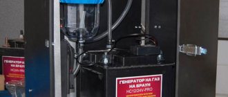
Wind generator on neodymium magnets with a power of 5.0 kW
Currently, domestic and foreign companies are increasingly using neodymium magnets in the manufacture of low-speed electric current generators. Thus, Salmabash LLC, Gatchina, Leningrad Region, produces similar permanent magnet generators with a power of 3.0-5.0 kW. The appearance of this device is shown below:
The generator housing and covers are made of steel, later coated with paint and varnish materials. The housing is equipped with special fastenings that allow you to secure the electrical device to the supporting mast. The inner surface is treated with a protective coating that prevents metal corrosion.
The generator stator is made of electrical steel plates.
The stator winding is made of enamel wire, allowing the device to operate for a long time at maximum load.
The generator rotor has 18 poles and is mounted in bearing supports. Neodymium magnets are placed on the rotor rim.
The generator does not require forced cooling, which is carried out naturally.
Technical characteristics of the 5.0 kW generator:
- Rated power – 5.0 kW;
- Rated frequency – 140.0 rpm;
- Operating rotation range – 50.0 – 200.0 rpm;
- Maximum frequency – 300.0 rpm;
- Efficiency – not less than 94.0%;
- Cooling – air;
- Weight – 240.0 kg.
The generator is equipped with a terminal box through which it is connected to the electrical network. The protection class corresponds to GOST 14254 and has a degree of IP 65 (dust-proof design with protection from jets of water).
The design of this generator is shown in the figure below:
where: 1-body, 2-bottom cover, 3-top cover, 4-rotor, 5-neodymium magnets, 6-stator, 7-winding, 8-coupling half, 9-seals, 10,11,12-bearings, 13 - terminal box.
Electrical and technical parameters of the generator
The voltage is calculated using the formula:
Homemade generator
U=2*Ch*KP*KK*KV*MI*P, where:
- U – voltage in Volts;
- H – frequency of rotation of the generator rotor per second;
- KP – number of magnetic poles;
- КК – number of induction coils in the stator;
- KV – the number of turns of the conductor in one induction coil;
- MI is the magnetic induction in T, which is formed in a standard gap (2 mm);
- P – surface area of one neodymium magnet, in sq. m.
If simple coils are used, a magnetic induction of 0.5 Tesla is taken for calculation. When adding an electrical steel core, the value is increased to 0.7-0.9 T.
For your information. The formula is valid when connecting the windings in a triangle. If a three-phase generator is assembled using a star circuit, the resulting value is multiplied by a correction factor of 1.7.
After calculating the voltage, you need to find out the resistance in the windings. After this, it will be easy to determine the current and power. For a copper conductor, the resistivity is 0.0175 Ohm per mm2/meter. To calculate the total value, use the formula:
C= (US*D)/PP, where:
- C – resistance, in Ohm;
- US – resistivity of a certain material;
- D – conductor length in meters;
- PP – conductor cross-sectional area, mm sq.
To calculate the current, subtract the voltage of the battery connected for charging from the voltage of the magnetic generator at idle. The resulting value is divided by the resistance value calculated using the previous formula.
Increasing/decreasing the speed changes the current accordingly while keeping the voltage at the battery terminals constant. To calculate the performance of a wind turbine in different modes, use the standard formula:
P=I*U, where:
- P – power, Watt;
- I – current strength, Ampere;
- U – voltage, Volt.
Advantages and disadvantages
The advantages of wind generators made using neodymium magnets include the following characteristics:
- High efficiency of devices, achieved by minimizing friction losses;
- Long service life;
- No noise or vibration during operation;
- Reduced costs for installation and installation of equipment;
- Autonomy of operation, allowing operation without constant maintenance of the installation;
- Possibility of self-production.
The disadvantages of such devices include:
- Relatively high cost;
- Fragility. Under strong external influence (impact), a neodymium magnet can lose its properties;
- Low corrosion resistance, requiring special coating of neodymium magnets;
- Dependence on operating temperature – when exposed to high temperatures, neodymium magnets lose their properties.
Low-speed wind generators
The most attractive wind turbine designs for most regions of Russia are those that give high performance in weak and medium winds - low-speed wind turbines. They are characterized by the ability to start rotating at low flow rates, producing sufficient voltage to power consumer devices.
Energy generation in such devices is carried out by generators adapted to work with wind turbines. The design specificity of such generators is high sensitivity, since the device is initially designed to operate at low rotation speeds.
In order to ensure the specified operating mode, it is necessary to exclude the excitation winding from the design, replacing it with permanent magnets. As a result, there will be no need to supply voltage to form electromagnets, and induction will become more stable, independent of the power source on the rotor winding. In addition, there will be no need for a brush assembly that supplies power to the field winding.