Description of the process of disconnecting the AC electrical circuit during a short circuit
When the switch contacts open, the current is not interrupted. According to Lenz's law, an emf EL=-Ldi/dt appears in the circuit, preventing a change in current. The latter finds a path for itself through the gas gap between the diverging contacts of the switch, which is blocked by an electric arc. To interrupt the current, the arc must be extinguished. In alternating current circuits, favorable conditions for arc extinction occur every time the current reaches zero, i.e. 2 times during each period. The diameter of the arc column, temperature and ionization of the gas decrease sharply. At some point in time, the current comes to zero and the arc discharge stops. However, the chain has not yet been broken.
After zero current in the gas gap, which is still somewhat ionized, the deionization process continues, i.e. the process of transforming it from a conductor into a dielectric, and in the electrical circuit the process of restoring the voltage at the switch contacts from a relatively small arc voltage to the mains voltage begins. These processes are interconnected. The outcome of the interaction of the arc gap with the electrical circuit depends on the relationship between the energy supplied to the gap and the energy losses in it, which depend on the arc extinguishing device of the switch.
If energy losses predominate throughout the entire transient process, the arc will not occur again and the circuit will be interrupted. Otherwise, the arc will arise again and the current will flow for another half of the period, after which the interaction process will repeat. The function of the switch is not so much to “extinguish” the arc, but rather to exclude the possibility of its re-ignition by effectively deionizing the gap by various artificial means. This uses the exceptional property of gas - quickly, within a few microseconds, to transform from a conductor into a dielectric capable of withstanding the restoring network voltage.
To understand the design and operation of switches, it is necessary to become familiar with the physical processes in the arc gap during the shutdown process. This article discusses arc extinguishing methods in air and oil circuit breakers.
Exposure to humans and electrical equipment
An electric arc poses a danger to humans due to its thermal effects, as well as the ultraviolet effect of the emitting light. High AC voltage poses a huge danger. If an unprotected person is at a critically close distance from live parts of devices, an electrical breakdown may occur with the formation of an arc. Then, in addition to the effect of current, the body will be affected by a thermal component.
The spread of an arc discharge through structural parts of equipment threatens to burn out electronic elements, boards and connections.
Physical processes in the arc gap of a switch at high pressure
An electric arc, or more precisely an arc discharge, is called an independent discharge in a gas, i.e. a discharge occurring without an external ionizer, characterized by a high current density and a relatively small voltage drop at the cathode. Below we consider the high pressure arc, i.e. arc discharge at atmospheric and higher pressure.
The following arc discharge areas are distinguished:
- area of cathode voltage drop;
- area near the anode;
- arc pillar.
The region of the cathode voltage drop is a thin layer of gas at the cathode surface. The voltage drop in this layer is 20-50 V, and the electric field strength reaches 105106 V/cm. The energy supplied from the network to this area is used to release electrons from the cathode surface.
The mechanism for releasing electrons can be twofold:
- thermionic emission with refractory and refractory electrodes (tungsten, coal), the temperature of which can reach 6000 K and higher
- field emission, i.e. the ejection of electrons from the cathode by the action of a strong electric field when the cathode is “cold”.
The current density at the cathode reaches 3000-10000 A/cm5. The current is concentrated in a small brightly lit area called the cathode spot. The released electrons move through the arc column to the anode.
At the anode, positive ions become accelerated towards the cathode. The electrons go to the anode and form a negative charge in a thin layer. The voltage drop at the anode is 10-20 V.
Processes in the arc column are of greatest interest when studying switches, since various types of influence on the arc column are used to extinguish the arc. The latter is plasma, i.e. an ionized gas with a very high temperature and equal amounts of electrons and positive ions per unit volume.
The high temperature in the arc column is created and maintained by electrons and ions that participate in the thermal chaotic movement of neutral molecules and atoms, but also have a directed movement in the electric field along the axis of the arc, determined by the sign of the charge of the particles. This movement is prevented by neutral gas. Frequent collisions of electrons and ions with neutral particles occur. Since the mean free path of electrons at high pressure is small, the energy loss during elastic collisions with molecules and atoms per collision is small and insufficient to ionize particles. However, the number of collisions that electrons undergo is very large. As a result, the energy of the electrons is transferred to the neutral gas in the form of heat.
The average energy of the “electron gas” cannot significantly exceed the average energy of the neutral gas, since the additional energy acquired by electrons and ions in their directed motion along the axis of the meadow column is small compared to the thermal energy of the gas. Consequently, ions, electrons, as well as neutral atoms and molecules are in thermal equilibrium. In this case, the specific ionization of the arc column is completely determined by temperature, and when one of these quantities changes, the other inevitably changes.
Because at high gas pressure atoms and molecules overwhelmingly outnumber electrons and have almost the same high temperature, most excited and ionized atoms and molecules are produced by collisions between neutral particles rather than by collisions with electrons. Thus, electrons do not ionize directly through collisions with neutral particles (as happens in a vacuum), but indirectly, increasing the temperature of the gas in the arc column. This ionization mechanism is called thermal ionization. The source of energy required for thermal ionization is an electric field.
There are energy losses in the arc column, which in a steady state are balanced by the energy received from the network. The bulk of the energy is carried away from the arc column by excited and ionized atoms and molecules. Due to the difference in the concentrations of charged particles in the arc column and the surrounding space, as well as the temperature difference, the ions diffuse to the surface of the arc column, where they are neutralized. These losses must be compensated by the formation of new ions and electrons associated with the expenditure of energy. In steady state, the voltage gradient in the arc column is always such that the ionization that occurs compensates for the loss of electrons through recombination. The voltage gradient depends on the properties of the gas, the state in which it is located (quiet, turbulent), as well as pressure and current. As gas pressure increases, the voltage gradient increases due to a decrease in the free path of electrons. As the current increases, the voltage gradient decreases, which is explained by an increase in the cross-sectional area and temperature of the arc column. The arc column tends to take on a cross-section such that, under the conditions under consideration, energy losses are minimal.
Current-voltage characteristics of the arc
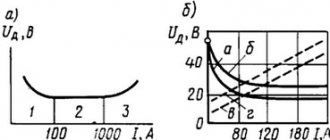
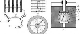
The dependence of the voltage gradient E = dU/dl in the arc column on the current with a very slow change in the latter is a static characteristic of the arc (Fig. 1, a), depending on the pressure and properties of the gas.
Fig.1. Current-voltage characteristics of the arc: a - static characteristic; b - dynamic characteristics
In a steady state, each point of the characteristic corresponds to a certain cross section and temperature of the arc column. When the current changes, the arc column must change its cross-section and temperature in relation to the new conditions. These processes take time, and therefore the new steady state does not occur immediately, but with some delay. This phenomenon is called hysteresis.
Let's assume that the current suddenly changes from the value I1 (point 1) to the value I2 (point 2). At the first moment, the arc will retain its cross sections and temperature, and the gradient will decrease (point 2′). The power supplied will be less than that required to carry current I2. Therefore, the cross section and temperature will begin to decrease, and the gradient will increase, until a new steady state occurs at point 2 on the static characteristic. If the current suddenly increases from value I1 to value I3, the voltage gradient will increase (point 3′). The power supplied to the arc will be greater than that required to conduct current I3. Therefore, the cross section and temperature of the column will begin to increase, and the voltage gradient will decrease until a new steady state occurs at point 3 on the static characteristic.
When the current changes smoothly at a certain speed, the voltage gradient does not have time to follow the current change in accordance with the static characteristic. When the current increases, the voltage gradient exceeds the values determined by the static characteristic, and when the current decreases, the voltage gradient is less than these values. Curves E=f(I) when the current changes at a certain speed represent the dynamic characteristics of the arc (solid lines in Fig. 1, b).
The position of these characteristics in relation to the static characteristic (see dotted curve) depends on the rate of change of current. The slower the current change occurs, the closer the dynamic characteristic is to the static one. Under a given arcing condition there can be only one static characteristic. The number of dynamic characteristics is not limited.
When analyzing electrical circuits, it is customary to operate with the concept of resistance. Therefore, they also talk about arc resistance, meaning by this the ratio of voltage at the electrodes to current. Arc resistance is not constant. It depends on the current and many other factors. As the current increases, the arc resistance decreases.
Fig.2. Arc voltage with alternating current: a - arc voltage as a function of current; 6 - arc voltage as a function of time
The current-voltage characteristic of an alternating current arc is shown in Fig. 2, a. During the quarter period, when the current increases, the voltage curve lies above the static characteristic. The next quarter of the period, when the current decreases, the voltage curve lies below the static characteristic.
The arc ignites at points 1 and 3 and goes out at points 2 and 4. Figure 2,b shows the characteristics of the arc as a function of time. Intervals 2-3 and 4-1 correspond to an unstable state in which there is intense interaction of the arc with the circuit constants R, L and C. These short time intervals, which last a few microseconds, are used to intensively deionize the gap between the switch contacts to prevent new arc ignition. Depending on the conditions, the interaction process can end in two ways: either the arc will go out and the circuit will be interrupted, or the arc will arise again and the interaction process will be repeated after half a period under more favorable conditions.
Structure
The electric arc consists of three main zones:
- cathode;
- anodic;
- plasma column.
In welding arcs, the dimensions of the cathode and anode zones are small compared to the length of the column. The thickness of these zones is thousandths of a millimeter. In the area of the cathode voltage drop (at the end of the negative electrode), the presence of cathode spots is observed, which are formed as a result of strong heating.
Figure 4 shows a diagram of the structure of the arc created by the welding machine.
Rice. 4. Welding arc structure
Please note: for the purpose of clarity, the electrode zones are greatly exaggerated in the picture. In reality, their thickness is measured in microns.
Arc extinction in air circuit breakers
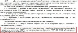
In air circuit breakers, the arc is extinguished in a high-pressure air stream. The switch extinguishing device (Fig. 3a) is a chamber in which two nozzles are placed, which simultaneously serve as contacts. The exhaust sides of the nozzles are connected to the low pressure area. When the contacts are separated, due to the pressure difference, an air flow occurs, directed into the nozzles symmetrically in both directions.
Fig.3. Arcing device of an air circuit breaker with double-sided blast: a - diagram; b - pressure distribution along the axis
Figure 3b shows the pressure distribution along the axis. In the middle of the gap between the nozzles there is a flow stagnation point, the pressure at which is indicated by po.
On both sides of this point the pressure decreases and reaches approximately half po at the nozzle necks. Behind the throats, the pressure continues to drop to exhaust pressure.
The arc extinguishing process proceeds as follows. An arc appears between the opening contacts, which, under the action of the air flow, is quickly transferred along the axis. In this case, the arc support spots move inside the nozzles along the flow, as shown in Fig. 3. The arc in the space between the nozzles has a cylindrical shape.
Fig.4. Temperature distribution in the transverse direction in the area between the nozzles: a - arc; c - thermal boundary layer
The temperature distribution in the transverse direction is shown in Fig. 4. In the arc zone a it is approximately 20,000 K and drops sharply towards the thermal boundary layer b formed near the arc. Here the temperature varies from 2000 K to cold air temperature. As the current approaches zero, the diameter of the cylindrical part of the arc rapidly decreases. When the current is zero, it is less than 1 mm. However, the temperature in this part of the arc is still very high (15000 K).
The most important factor contributing to arc extinction is turbulence in the boundary layer between the arc and the relatively cold air surrounding it. Due to the high temperature of the arc, the gas density in the column is approximately 20 times less than in the environment. Therefore, the gas velocity inside the arc column is significantly higher than the velocity in the neighboring layers (the velocity is inversely proportional to the square root of the density). Due to the diffusion of particles from an area with high speed to an area with low speed and back, significant shear forces arise in the boundary layer, vortices are formed and the entire volume acquires high turbulence. A relatively cold non-ionized gas is introduced into the arc column, as a result of which the column loses its homogeneity. It splits into thousands of the finest conductive threads, continuously changing their shape and position (Fig. 5).
Fig.5. The influence of turbulence on the arc column near zero current (scheme)
They have a high temperature and high specific ionization and are surrounded by cold, weakly ionized gas. It is known that the rate of diffusion from a cylindrical volume is inversely proportional to the square of the diameter. The thinner the ionized filaments, the faster the exchange of particles with the surrounding colder and less ionized environment occurs. Turbulence increases diffusion many times over. It manifests itself especially sharply in the throats of the nozzles, where the plasma speed is maximum - 6000 m/s. After zero current, for a short period of time, measured in microseconds, the conductive channel disintegrates and a further decrease in temperature is determined by the thermal boundary layer, the cooling of which occurs much more slowly.
Fig.6. Equivalent diagram explaining the influence of arc resistance and capacitance
Fig.7. Interaction of the arc with the electrical circuit
The arc resistance and capacitance connected parallel to the arc gap have a significant influence on the shutdown process (Fig. 6). If we neglect the arc resistance, the current i0=Imsinɷt approaches zero almost linearly (Fig. 7). However, the arc resistance is not zero. Therefore, the current iB in the arc gap of the switch decreases:
(1)
where t0 is the moment of contact opening.
As can be seen from the figure, the arc voltage changes in accordance with the current-voltage characteristic. The rate of current decrease decreases significantly during the last 5...10 μs before it reaches zero. This time is small, but it is several times greater than the arc time constant and therefore significantly affects the state of the arc at zero current (point 1). The arc goes out easily. The arc resistance also modifies the PVN curve. The voltage recovery process begins at point 1; the voltage reaches its maximum at point 2 when iL=iC=0.
Stage of possible thermal breakdown
If the temperature of the gas in the gap does not decrease to a certain critical value determined by the gas property and pressure, the gap will retain its conductivity after zero current (point 1) and under the influence of the PVN a residual conductivity current will arise (Fig. 8).
Fig.8. Arc extinction with a delay caused by the appearance of residual conduction current
Under favorable conditions, it is small and quickly fades (point 2). However, if the cooling process is not intense enough, the residual conduction current increases; The plasma is reheated, the ionization process resumes, and the arc occurs again. This phenomenon is called thermal breakdown, since electrical breakdown is impossible, since the gap is ionized and has not yet acquired electrical strength.
Whether such a breakdown occurs or not depends on the outcome of two interrelated processes occurring in the gap, one of which is determined by the time integral of the supplied power (the product of current and voltage across the gap), and the second by the time integral of losses caused by thermal conductivity and convection. This means that the interaction process will continue until the current disappears or the arc occurs again. The phenomenon of thermal breakdown is typical for the first 20 μs after zero current under conditions when the speed of voltage recovery is high, for example, with unremoved short circuits.
Stage of possible electrical breakdown
If thermal breakdown does not occur, the intercontact gap continues to be exposed to the influence of the PVN. The arc channel has an even higher temperature and lower density. A few hundred microseconds after zero current, when the PVN reaches its maximum value, the stage of possible electrical breakdown begins. It is based not on energy balance, but on the process of electron formation in an electric field. If the increase in electron concentration exceeds a certain critical value, a spark will form, which will turn into an arc discharge.
Arc extinction in oil circuit breakers
In oil switches, the contacts open in oil, but due to the high temperature of the arc formed between the contacts, the oil decomposes and the arc discharge occurs in a gaseous environment. Approximately half of this gas (by volume) is oil vapor. The rest consists of hydrogen (70%) and hydrocarbons of various compositions. These gases are flammable, but combustion in oil is impossible due to the lack of oxygen. The amount of oil decomposed by the arc is small, but the volume of gases produced is large. One gram of oil gives approximately 1500 cm3 of gas, reduced to room temperature and atmospheric pressure.
Arc extinguishing in oil switches occurs most effectively when using extinguishing chambers, which limit the arc zone, contribute to an increase in pressure in this zone and the formation of a gas blast through the arc column. Figure 9 shows a diagram of the simplest extinguishing chamber.
Fig.9. Diagram of the simplest extinguishing chamber of an oil switch
During the shutdown process, contact rod 1 moves downwards. An arc occurs between pins 1 and 2. Intense gas formation occurs and the pressure in the chamber quickly increases. The relatively cold gas formed on the surface of the oil mixes with the arc plasma. The boundary layer enters a turbulent state, promoting deionization. However, the arc cannot go out until the distance between the contacts reaches a certain minimum value determined by the recovery voltage. This minimum gap occurs when the moving contact is still in the chamber. When the rod leaves the chamber, the gases are thrown out with force. A gas blast occurs, directed along the axis, helping to extinguish the arc.
After the arc is extinguished, the contact rod continues its movement to ensure the required insulation distance in the off position.
The arc voltage of an oil circuit breaker is at least 3 times that of an air circuit breaker. The electrical strength of the gap is restored faster (at a rate of about 2 kV/µs). Therefore, with the same short-circuit current, the arc extinguishing device of the oil circuit breaker can be designed for twice the voltage and twice the characteristic impedance than the air blast device.