To assemble a GPS antenna with your own hands at home, first prepare all the necessary materials, tools, and study the operating algorithm. A homemade device will help boost the signal on any gadget equipped with a sensor that can be connected to.
A GPS antenna is a device designed to enhance the signal of devices.
Tips for choosing an antenna
When purchasing an antenna, you must take into account the technical characteristics of the device, the range of possible signals, the power of the device, location, type of mounting allowed in the car model, etc.
It is necessary to determine the necessary functions:
- fixation of radio signals;
- determination of television signals (digital or analogue TV);
- reception of navigation data (GPS).
The devices can operate to receive one type of signal or function in a complex manner. Multifunctional devices are practical, ergonomic, and save the cost of equipping the machine.
In terms of cost, products fall into the budget, medium and high categories. The choice of antenna is affected by the type of radio for the car. For simple equipment, you can purchase an average-cost antenna. A radio with additional sensors requires a combination antenna. The cost of average quality antennas is 2-2.5 thousand rubles.
It is important to determine the technical characteristics of the device and the signal reception range. Devices can be simple or equipped with a Bluetooth system, the equipment can be combined (GPS/GSM)
Selection includes determining the area for mounting equipment in accordance with the machine model. The determining criterion is the device’s access to the Internet.
It is necessary to pay attention to the equipment included in the device. For comfortable operation, the cable length is taken into account
The element must be shielded, with a large cross-sectional area and the length required for the car model (passenger car, truck).
A brief overview of some models of TV antennas for cars
The CL/CC25 satellite television antenna is designed to receive signals in the range from 10.7 to 12.7 GigaHertz.
Its tracking speed is 100 arc degrees per second. This speed is achieved through the use of phased array antenna technologies with mechanical drives.
The antenna has a high cost (from 2,000 USD) and is used to serve bus excursion groups at great distances from large populated areas and special facilities.
The active television antenna Orion A-72 is designed for installation inside the cabin. This is not entirely optimal in terms of reception range, however, such an antenna is protected from vandalism. The antenna is also operational in the FM radio signal range. Has a gain of 20dB.
The GSTAR GS-NV 003-5V antenna with a gain of 39 dB is installed using a powerful magnet on the roof of the car. Great for occasional trips to the country. Has a circular radiation pattern. Powered by a DVB receiver. Cannot work in analog format.
The Prology TVA-100 TV antenna is designed to receive digital and analogue broadcasting signals, powered from the vehicle’s on-board network. Installed inside the cabin. Gain 30 dB. Installed in budget cars.
With the introduction of digital television broadcasting standards, the use of televisions in cars becomes relevant. Modern standard multimedia complexes allow you to reproduce a television signal with high quality. By installing a DVB receiver and a TV antenna, you can get another benefit of civilization in your car.
However, the specifics of vehicle operation should be taken into account. If trips are made at a short distance from a large city (within 70 kilometers), then the reception will be quite reliable. In the case of long-distance commercial trips, monitoring television transmitting stations yourself becomes problematic.
Video - installation of a car TV antenna B3TV (Ozar) for a digital DVBT2 signal:
May be of interest:
Scanner for self-diagnosis of a car
How to quickly get rid of scratches on a car body
How to check a used car before buying
How to apply for an MTPL policy online in 7 minutes
Cost of radio antennas
If we talk about the price of the issue, then the cheapest will be a regular whip antenna, which can be purchased in the range of 300-500 rubles. Apart from the SMA connector and a two-meter cable, it doesn’t come with anything interesting.
An active GPS/GLONASS antenna, for example, Beyondoor ANT GPS BY-GPS/GLONASS07, will cost more, about 1,400 rubles. But at the same time, the device is equipped with a built-in 27 dB amplifier and allows you to connect a car radio, navigator or hybrid device.
Another model with the Glonass system is the Shark Fin FM/AM/GPS/GLONASS for 6,000 rubles. In addition to the SMA connector, the device also allows you to connect a DIN plug. But, there is no amplifier in this model, since the signals travel over a wide frequency range with low noise
If the amplifier is important to you, then you can pay attention to another “Shark Fin” V-SMA3M-2FM-TV for 9,000 rubles. With a gain of 4 dB, the antenna produces a decent signal
How to connect an external antenna to your device
When purchasing an external GPS antenna, you must clearly explain to the seller what device you are buying it for; this must be done, since modern signal amplifiers can be used using a USB port, as well as Bluetoot, namely, you can connect it yourself:
- A signal amplifier with a Bluetooth connection is ideal for a smartphone; all parameters will be transmitted using a special protocol, you do not need additional connectors;
- PCs and laptops now have a USB/PS2 connector installed, so you can choose an external amplifier to connect through it;
- Some tablets do not have a USB input, then the solution is to connect via Bluetoot; the effectiveness of this antenna is achieved by an autonomous power supply and the need to correctly install the antenna mount.
Rules for the location of gadgets
When working with any device that performs the functions of a navigator, it is necessary to take into account nuances that can affect the quality of signal reception and transmission.
To ensure that satellite communications are always at their best, you should pay attention to the following factors:
- If you notice that the GPS in your car does not pick up satellites, take into account the negative impact of coated glass. This most often happens if you place the antenna directly on the top edge of the windshield, where the frits are located that protect the urethane sealant from ultraviolet rays. The idea of placing a receiving device on the rear window will also not lead to a positive result, but will only aggravate the situation.
- The standard GPS receiver built into mobile devices is far from the best solution for navigation, so in any case you will need to use additional equipment with it, otherwise there is a risk of receiving inaccurate location information.
In the first case, the problem can be solved by changing the location of the antenna. If it needs to look directly at the sky, it should be fixed a little lower on the windshield so that it is not located directly on the site of the frits. An excellent option would be to secure the device under the roof. The mortise type of mounting of the GPS receiver allows you to achieve maximum results. To do this, a small hole is made on top of the body from where the antenna is brought out.
A GPS signal amplifier is designed to solve the second problem. Taking into account consumer demand, such devices are equipped with modern communication systems such as USB and Bluetooth. This allows you to save space in the cabin, then there is no need to connect another cable to your tablet or smartphone. The amplifier has a built-in battery and can be charged using a standard mobile phone charging cable. They are also compatible with on-board computers via USB.
Video
An external GPS receiver, aka a portable GPS module, aka an external GPS antenna, aka an external GPS unit, whatever you call it, in any case, this is a unique device that can turn any computer, PDA or tablet into a full-fledged navigator . Modern mobile devices rarely boast good GSM or GPS signal reception. And laptops are generally extremely rarely able to pick up GPS signals. It's all about the antenna. And if it is not there, then you can buy it and install a separate external GPS receiver
. And one of the best solutions in this matter is GlobalSat!
If for some reason the classic navigator does not suit you (for example, the display is not large enough, or functionality that you simply do not need), then you can simply buy an external GPS module
;
and the required navigation map (topographic, road or depth map) and that’s it - your computer, which you know like the back of your hand, will turn into a navigator. You can take your laptop in the car or travel with it while tracking yourself through Google services
.
GPS receivers
there are different ones. There are Bluetooth devices on sale, as well as wired ones. There are different connection connectors and different operating conditions. Check out our range and if you are still in doubt, call us!
A friend asked me to find him a tablet with GPS for driving through forests and cities, so as not to get lost and that it also had Bluetooth to connect an external GPS receiver. The choice fell on an external GPS antenna, a resistive 10″ screen, a normal hole for a USB device, and even an Ethernet interface. (ATTENTION this is a repost from Habr)
Characteristics
CPU:
1GHz CORTEX A9
GPU:
Mali 400
RAM:
512MB or 1024MB (depending on the age of the model)
ROM:
8GB (of which 6 GB are available to the user as a nand flash drive and about 1GB more for programs), versions with 4GB and 16GB are also available
Screen:
10.2″ 1024×600 resistive multi-touch (in fact, it just understands gestures in software, like pinch to zoom)
Communications:
WiFi b/g/n, Ethernet and 3G modems via USB-host
GPS:
built-in, but external antenna on a long wire
Interfaces:
USB-Host, USB-OTG, RJ-45, HDMI, 3.5mm audio, microSD memory card slot
Multimedia:
built-in stereo speakers, front 0.3 megapixel camera for Skype
Battery:
could not be found out, but it seems that depending on the model /seller ranges from 3Ah to 7Ah and judging by the weight, I did not get a model with 7Ah
Dimensions:
270 x 170 x 16 mm
Weight:
700 grams (it seemed smaller to me)
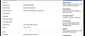
The official website of the manufacturer, there are also new firmware versions and, judging by the dates, support for the tablet has not been abandoned, as is usually the case, but has been discontinued (according to the manager of the buysku.com store), but it looks like this is its clone or twin.
Appearance and interfaces
When the box with the tablet arrived, I was a little surprised by the size; after all, 10″ is too much.
On the front panel there is a screen, a back button and a 0.3Mpx camera peephole. On the right side are all the interface connectors: DC-in, Ethernet (probably useful for someone, I just tried it and it works great), HDMI, USB-OTG, microSD, USB-host (very tight, if a device gets in there, you can’t accidentally pull it out will work), 3.5mm headphone jack.
On top of the device: an incomprehensible switch (I thought it was hold, but it doesn’t block anything), speakers (left and right), lock button, menu, volume rocker, power button, microphone, connector for an external GPS antenna and a stylus (I was nostalgic, really useful and handy thing).
Nothing interesting was found on other sides.
Accessories: external GPS antenna (for which everything was started), a charger with a USB cable and an adapter for a European socket, as well as instructions for using version 4 of Android.
Performance testing
Here I apologize in advance, I didn’t have much time to test the tablet properly and take beautiful photos, and I also didn’t notice that you can take normal screenshots, and not “screenshots”.
Electopia
AnTuTu
Quadrant
As you can see, the performance is not bad at all and most games work, but the controls are not so great, since most are designed for multi-touch.
Browser, Skype and other information
But surfing the Internet is a real pleasure - sites look the same as they do on a large computer.
Skype supports video calls, but the picture slows down noticeably (5-10fps to the eye) and the camera of the tablet itself looks higher than it should, as a result the interlocutor sees the top of my head.
Example of a photo from a camera
Multitouch is implemented in software, since the screen technology does not allow us to normally determine the number and coordinates of clicks. Therefore, only one touch fully works. I thought that with such a large screen size there would be a lot of false positives, and in general it would work poorly, but it turned out to be completely wrong - any poke on the screen works very accurately, and with the stylus you can even write calligraphically.
System information:
GPS
It's time to talk about GPS; in fact, this is the only reason I bought the tablet for a friend.
The rest of the story is from him, but sometimes I’ll chime in. Based on the seller’s description, you can’t clearly understand what the built-in GPS module is, so testing comes down to a comparative analysis with the external wireless GPS module Holux M1000.
Testing within the apartment.
The module built into the tablet performed well and, with the antenna hung on the window, easily caught up to 10 satellites and was quite stable.
Lyrical digression: the tablet was initially purchased only to be used as a navigator with an external module connected via Bluetooth. The manufacturer stated that the VT would be built-in (actually I stated this, the seller wrote strange support, which meant possible support, as with 3G modems, but I hoped that support=built-in)
, but upon receipt of the parcel, a USB-BT-dongle was discovered
(which I took out from the bins of my homeland, there was nothing in the kit)
, which is inserted into the USB and, accordingly, sticks out, causing a lot of inconvenience. Let's get back to our testing. We connect an external GPS Holux M1000 via BT, there were no problems with this, the tablet happily paired with it without a single delay.
Holux also caught 10-11 satellites, but with a more stable signal than the built-in module. Although the difference is not particularly noticeable.
Testing in city navigation conditions.
During this test, there was a big disagreement between the built-in module and the external one. The built-in one caught 5-6 satellites, compared to 11-12 for Holux.”a.
Testing in nature, far outside the city.
Outside the city, in the open air, both navigators showed approximately the same results as in the city, with only a slight difference: the receiver built into the tablet sometimes lost the signal. Actually, there wasn’t much opportunity to take photographs; I’ll attach just a couple of photos from the last testing site.
Impression.
The GPS module built into the tablet should be used only if you are within the city; it receives satellites stably and works well with navigation programs, such as. The
GPS antenna is used to determine with special devices the coordinates of the area in which a person is located at that particular moment. Recently, our country has its own development in this area - the GLONASS system. Modern GPS receivers, without additional clarification systems, have sufficient accuracy to determine location - in the region of 3 meters.
How to properly install a GPS antenna in a car
Before installation, it is important to determine the optimal location for the antenna. Experts recommend placing the devices on the roof of the car or on other surfaces of the technical equipment.
An antenna located perpendicularly encounters less interference and transmits the signal quickly. It is optimal to place the device under the roof, on the top of the windshield of the car.
The signal from the device on the rear window or in the lower block of the windshield arrives with less intensity, but the device will be preserved better. It is not recommended to place the device near lamps, because reception quality will decrease due to electromagnetic radiation.
The structure is attached in several ways:
- magnetic;
- overhead (with a clamp);
- mortise;
- internal.
The magnetic method allows you to fix the device in different parts of the machine. The mount has a budget price, simple installation, does not require openings in the body of the equipment during installation, and reduces the risk of deformation. However, it is necessary to remove the device in parking lots to prevent theft.
It is important to take into account the short length of the receiving dipole, which makes it difficult to determine signals in desert areas
The overhead mount allows you to install the device on the car body using brackets and threaded connections. The device is attached to the rear bumper or drain of the car. An amplifier is not provided in antennas with a surface-mounted type of fastener; it is necessary to take into account the compatibility of the product with the design of the machine.
The mortise antenna is mounted through a hole in the car body (front or rear fender). The opening is treated with a composition that prevents corrosion. The method allows you to hide the mounting pin. It is necessary to regularly process the hole and monitor the integrity of the structure.
Internal installation of the technical device is recommended for GPS modules. The device is placed on the top of the windshield; the surfaces are treated with a special compound before installation. The devices require connection to a satellite signal amplifier and a dedicated power source. The interior antenna is equipped with adjustable gain intensity, does not create noise, does not require complex maintenance and reconstruction of the machine, and has no risk of deformation during operation.
Advantages and disadvantages of homemade devices
One of the advantages of a homemade car antenna is the ability to more accurately adjust to reception conditions by choosing the length of the receiving pin and the installation location on or inside the vehicle body. With careful and correct assembly, the sensitivity and bandwidth of a homemade receiving device will be no worse than that of a factory one.
One of the disadvantages of homemade antennas is the need to drill into the car body. Over time, the hole may rust. Some homemade antennas may not comply in their dimensions with the Road Traffic Regulations.
Step-by-step instructions for assembling the antenna yourself
To assemble an antenna for a phone or Starline you will need:
- arduino mini or arduino nano board;
- insulating tape;
- piece of wire;
- pliers;
- soldering iron;
- copper wire.
First, the wire is bent with pliers to form a square. Observe the proportions strictly to avoid disruptions in work. The part is then soldered or attached with electrical tape to the patch on the receiver. For soldering, a stranded wire extending from the board is used. Then the device is installed using 2 pieces of double-sided tape.
Before making the antenna, make sure that you can reach the GPS module in the navigator. In Chinese trackers and smartphones, such a connection is easy.
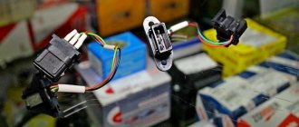
Specifications
An antenna is a universal equipment that consists of several components. The device is characterized by the presence of a main unit, a signal capture unit and a wire. The device is connected to a car alarm using a wire. The main block contains a board that is used to process various signals. The starline catching device has an ultra-sensitive sensor that captures the signal. The equipment is characterized by:
- Simplicity of design;
- Duration of use;
- Small in size.
The antenna is manufactured from the highest quality materials, which ensures long-term operation. The main body of the equipment is made of impact-resistant plastic, which provides it with a high degree of resistance to various mechanical damage. Due to the integrity of the antenna housing, the possibility of dust, dirt, and moisture getting inside is limited. The antenna is characterized by fairly small dimensions, which allows it to be installed in any place convenient for the user in the vehicle. The equipment is made in black, which makes it easy to hide from prying eyes. Connecting the device to the alarm system is quite simple, which allows a technician to perform this action without relevant experience.
Classification
GPS antennas for car radios are divided into:
- external;
- internal.
External devices are designed to search for radio and television signals. The device is highly sensitive and is mounted on the outside of the machine. It is necessary to take into account the exposure of the device to precipitation and changes in temperature conditions. The equipment is equipped with an adapter that increases the search parameters for radio frequencies. External devices are attached to the body, trunk, roof, bumper or fenders of the car.
In-cabin devices are mounted on the windshield of a car. The equipment is equipped with amplifiers inside the housing. The device is universal, suitable for different types of car radios, does not require complex installation work, but is very expensive.
An active GPS antenna is a standard device, the system of which is supplemented by an internal signal amplifier. The devices are sensitive, accurately and quickly detect a large number of radio and television waves. The device reduces the amount of interference and noise when playing music and videos.
The functionality of a passive type device depends on the volume of electromagnetic radiation in the area. If there is a small amount of interference, the reception of the radio signal will be stable, but if there are electrical appliances within the range (in cities), the reception accuracy will decrease.
By type of design, devices are divided into:
- asymmetrical;
- dipole.
A device with an asymmetrical housing is mounted perpendicular to the plane of radio frequency propagation. The equipment is equipped with a telescopic structure, consisting of parts that are unfolded manually or using an electric drive. The antenna includes a pin equipped with a spiral at the base.
Dipole devices are equipped with 2 rods located symmetrically. The devices are mounted in a horizontal position. The type of equipment is optimal for placement inside the car.
Cable selection for AUGRA
Radio antenna devices permanently installed on the car (mortise and pin mounts) have good contact with the metal of the body. The input impedance of commercially produced antennas is 50 Ohms, and a standard RG-58 coaxial antenna cable with an outer diameter of 5.0 mm fits perfectly with them. A cable length of more than 5 meters is not recommended due to the increasing attenuation of the received signal.
Automatic gearboxes installed on a car magnetically are not electrically connected to the body. To connect them with the radio, we recommend cables RG-213 or RK 50-7-11 with an outer diameter of 10.5 mm. The cable length is determined to be 360-390 cm. Changing the length in any direction from this indicator leads to the loss of the possibility of high-quality configuration of the equipment.
Installation
GPS module for car radio
A common place to install an antenna is on the roof of a car. This is the first thing that comes to mind for a person who decides to install it himself. But there can be many places for mounting a GPS antenna, and the roof in this case is not the only option.
Let's consider several options:
It is advisable to install the GPS antenna in the upper part of the windshield, facing the sky. Here such an antenna will encounter the least number of obstacles in order to receive reliable reception of signals from the satellite;
On the windshield
- The lower area of the windshield can also be chosen as an installation location, only here the antennas will have less potential;
- The same effect as the lower area of the windshield will be achieved by installing an antenna on the rear window;
- Whatever the disadvantages of the above-described places for installing antennas, they are considered as the most favorable installation options. But installing a GPS antenna near the street lights is a completely bad decision.
GPS module for car radio
So, there can be several ways to mount an antenna; everyone chooses their own option individually. As for the method of fastening, it can also be different.
Understanding the importance of the correct zone for installation is important so that there are no problems in the future. A few words of general information about the principle of operation of the satellite navigator will help to understand a lot:
Each navigation satellite transmits radio signals. They are received, amplified, converted to intermediate frequency, and then further processing continues.
- As a rule, the navigator (see 1 din car radio with navigator: device and installation) knows the coordinates of several satellites and the distances to them. But it's not that simple. To solve this navigation problem, it is necessary to determine 4 unknown quantities: these are three known geometric quantities and the offset of the receiver clock;
- Interestingly, to increase GPS accuracy, the navigator tries to use as many satellites as possible;
- The GPS antenna acts as a component that helps the navigator better receive signals, but even the most seemingly insignificant diffraction effects can be significant.
GPS receiver for car radio
Scheme for receiving GPS satellite antennas depending on installation
As the diagram indicates, the car body is not an obstacle to receiving signals from the satellite. The antenna under the windshield sees and receives the same satellites as on the roof. As for the antenna between the seats, it is only inferior to a couple of satellites. It turns out, in the end, that the geometric factor does not depend on the installation of the antenna? But, not everything is so simple. Only one thing can be said for sure: it is better to install a satellite antenna on the windshield, and not too deep into the cabin.
Types of fastening
GPS receiver for car radio
Satellite dishes can have different types of mounting:
- The mortise mount of the antenna involves fixing it through a hole that is made by drilling in the body. In this case, the edges of the holes must be treated with an anti-corrosion substance;
- Magnetic mounting means installing the antenna anywhere on the body, depending on your own preferences;
- The pin mount involves fixing the antenna to the car drain;
- Finally, internal mounting, which involves installing an antenna on the windshield, will require mandatory treatment of the glass with a special liquid.
Connecting the module to Arduino
Let's prepare the programmer for firmware:
Then we flash this sketch into Nano:
Additional Information
// ArduinoISP // Copyright © 2008-2011 Randall Bohn // If you require a license, see // https://www.opensource.org/licenses/bsd-license.php // // This sketch turns the Arduino into a AVRISP using the following Arduino pins: // // Pin 10 is used to reset the target microcontroller. // // By default, the hardware SPI pins MISO, MOSI and SCK are used to communicate // with the target. On all Arduinos, these pins can be found // on the ICSP/SPI header: // // MISO °. . 5V (!) Avoid this pin on Due, Zero... // SCK. . MOSI // . . GND // // On some Arduinos (Uno,...), pins MOSI, MISO and SCK are the same pins as // digital pin 11, 12 and 13, respectively. That is why many tutorials instruct // you to hook up the target to these pins. If you find this wiring more // practical, have a define USE_OLD_STYLE_WIRING. This will work even when not // using an Uno. (On an Uno this is not needed). // // Alternatively you can use any other digital pin by configuring // software ('BitBanged') SPI and having appropriate defines for PIN_MOSI, // PIN_MISO and PIN_SCK. // // IMPORTANT: When using an Arduino that is not 5V tolerant (Due, Zero, ...) as // the programmer, make sure to not expose any of the programmer's pins to 5V. // A simple way to accomplish this is to power the complete system (programmer // and target) at 3V3. // // Put an LED (with resistor) on the following pins: // 9: Heartbeat — shows the programmer is running // 8: Error — Lights up if something goes wrong (use red if that makes sense) // 7 : Programming - In communication with the slave // #include "Arduino.h" #undef SERIAL #define PROG_FLICKER true // Configure SPI clock (in Hz). // Eg for an ATtiny @ 128 kHz: the datasheet states that both the high and low // SPI clock pulse must be > 2 CPU cycles, so take 3 cycles ie divide target // f_cpu by 6: // #define SPI_CLOCK ( 128000/6) // // A clock slow enough for an ATtiny85 @ 1 MHz, is a reasonable default: #define SPI_CLOCK (1000000/6) // Select hardware or software SPI, depending on SPI clock. // Currently only for AVR, for other architectures (Due, Zero,...), hardware SPI // is probably too fast anyway. #if defined(ARDUINO_ARCH_AVR) #if SPI_CLOCK > (F_CPU / 128) #define USE_HARDWARE_SPI #endif #endif // Configure which pins to use: // The standard pin configuration. #ifndef ARDUINO_HOODLOADER2 #define RESET 10 // Use pin 10 to reset the target rather than SS #define LED_HB 9 #define LED_ERR 8 #define LED_PMODE 7 // Uncomment following line to use the old Uno style wiring // (using pin 11, 12 and 13 instead of the SPI header) on Leonardo, Due... // #define USE_OLD_STYLE_WIRING #ifdef USE_OLD_STYLE_WIRING #define PIN_MOSI 11 #define PIN_MISO 12 #define PIN_SCK 13 #endif // HOODLOADER2 means running sketches on the ATmega16U2 serial converter chips // on Uno or Mega boards. We must use pins that are broken out: #else #define RESET 4 #define LED_HB 7 #define LED_ERR 6 #define LED_PMODE 5 #endif // By default, use hardware SPI pins: #ifndef PIN_MOSI #define PIN_MOSI MOSI #endif #ifndef PIN_MISO #define PIN_MISO MISO #endif #ifndef PIN_SCK #define PIN_SCK SCK #endif // Force bitbanged SPI if not using the hardware SPI pins: #if (PIN_MISO != MISO) || (PIN_MOSI != MOSI) || (PIN_SCK != SCK) #undef USE_HARDWARE_SPI #endif // Configure the serial port to use. // // Prefer the USB virtual serial port (aka. native USB port), if the Arduino has one: // - it does not autoreset (except for the magic baud rate of 1200). // — it is more reliable because of USB handshaking. // // Leonardo and similar have an USB virtual serial port: 'Serial'. // Due and Zero have an USB virtual serial port: 'SerialUSB'. // // On the Due and Zero, 'Serial' can be used too, provided you disable autoreset. // To use 'Serial': #define SERIAL Serial #ifdef SERIAL_PORT_USBVIRTUAL #define SERIAL SERIAL_PORT_USBVIRTUAL #else #define SERIAL Serial #endif // Configure the baud rate: #define BAUDRATE 19200 // #define BAUDRATE 115200 // #define BAUDRATE 1000000 #define HWVER 2 #define SWMAJ 1 #define SWMIN 18 // STK Definitions #define STK_OK 0x10 #define STK_FAILED 0x11 #define STK_UNKNOWN 0x12 #define STK_INSYNC 0x14 #define STK_NOSYNC 0x15 #define CRC_EOP 0x20 //ok it is a space… void pulse (int pin, int times); #ifdef USE_HARDWARE_SPI #include "SPI.h" #else #define SPI_MODE0 0x00 class SPISettings { public: // clock is in Hz SPISettings(uint32_t clock, uint8_t bitOrder, uint8_t dataMode) : clock(clock) { (void) bitOrder; (void) dataMode; }; private: uint32_t clock; friend class BitBangedSPI; }; class BitBangedSPI { public: void begin() { digitalWrite(PIN_SCK, LOW); digitalWrite(PIN_MOSI, LOW); pinMode(PIN_SCK, OUTPUT); pinMode(PIN_MOSI, OUTPUT); pinMode(PIN_MISO, INPUT); } void beginTransaction(SPISettings settings) { pulseWidth = (500000 + settings.clock - 1) / settings.clock; if (pulseWidth == 0) pulseWidth = 1; } void end() {} uint8_t transfer (uint8_t b) { for (unsigned int i = 0; i < 8; ++i) { digitalWrite(PIN_MOSI, (b & 0x80) ? HIGH : LOW); digitalWrite(PIN_SCK, HIGH); delayMicroseconds(pulseWidth); b = (b << 1) | digitalRead(PIN_MISO); digitalWrite(PIN_SCK, LOW); // slow pulse delayMicroseconds(pulseWidth); } return b; } private: unsigned long pulseWidth; // in microseconds }; static BitBangedSPI SPI; #endif void setup() { SERIAL.begin(BAUDRATE); pinMode(LED_PMODE, OUTPUT); pulse(LED_PMODE, 2); pinMode(LED_ERR, OUTPUT); pulse(LED_ERR, 2); pinMode(LED_HB, OUTPUT); pulse(LED_HB, 2); } int error = 0; int pmode = 0; // address for reading and writing, set by 'U' command unsigned int here; uint8_t buff[256]; // global block storage #define beget16(addr) (*addr * 256 + *(addr+1) ) typedef struct param { uint8_t devicecode; uint8_t revision; uint8_t progtype; uint8_t parmode; uint8_t polling; uint8_t selftimed; uint8_t lockbytes; uint8_t fusebytes; uint8_t flashpoll; uint16_t eeprompoll; uint16_t pagesize; uint16_t eepromsize; uint32_t flashsize; } parameter; parameter param; // this provides a heartbeat on pin 9, so you can tell the software is running. uint8_t hbval = 128; int8_t hbdelta = 8; void heartbeat() { static unsigned long last_time = 0; unsigned long now = millis(); if ((now - last_time) < 40) return; last_time = now; if (hbval > 192) hbdelta = -hbdelta; if (hbval < 32) hbdelta = -hbdelta; hbval += hbdelta; analogWrite(LED_HB, hbval); } static bool rst_active_high; void reset_target(bool reset) { digitalWrite(RESET, ((reset && rst_active_high) || (!reset && !rst_active_high)) ? HIGH : LOW); } void loop(void) { // is pmode active? if (pmode) { digitalWrite(LED_PMODE, HIGH); } else { digitalWrite(LED_PMODE, LOW); } // is there an error? if (error) { digitalWrite(LED_ERR, HIGH); } else { digitalWrite(LED_ERR, LOW); } //light the heartbeat LED heartbeat(); if (SERIAL.available()) { avrisp(); } } uint8_t getch() { while (!SERIAL.available()); return SERIAL.read(); } void fill(int n) { for (int x = 0; x < n; x++) { buff[x] = getch(); } } #define PTIME 30 void pulse(int pin, int times) { do { digitalWrite(pin, HIGH); delay(PTIME); digitalWrite(pin, LOW); delay(PTIME); } while (times—); } void prog_lamp(int state) { if (PROG_FLICKER) { digitalWrite(LED_PMODE, state); } } uint8_t spi_transaction(uint8_t a, uint8_t b, uint8_t c, uint8_t d) { SPI.transfer(a); SPI.transfer(b); SPI.transfer©; return SPI.transfer(d); } void empty_reply() { if (CRC_EOP == getch()) { SERIAL.print((char)STK_INSYNC); SERIAL.print((char)STK_OK); } else { error++; SERIAL.print((char)STK_NOSYNC); } } void breply(uint8_t b) { if (CRC_EOP == getch()) { SERIAL.print((char)STK_INSYNC); SERIAL.print((char)b); SERIAL.print((char)STK_OK); } else { error++; SERIAL.print((char)STK_NOSYNC); } } void get_version(uint8_t c) { switch © { case 0x80: breply(HWVER); break; case 0x81: breply(SWMAJ); break; case 0x82: breply(SWMIN); break; case 0x93: breply('S'); // serial programmer break; default: breply(0); } } void set_parameters() { // call this after reading parameter packet into buff[] param.devicecode = buff[0]; param.revision = buff[1]; param.progtype = buff[2]; param.parmode = buff[3]; param.polling = buff[4]; param.selftimed = buff[5]; param.lockbytes = buff[6]; param.fusebytes = buff[7]; param.flashpoll = buff[8]; // ignore buff[9] (= buff[8]) // following are 16 bits (big endian) param.eeprompoll = beget16(&buff[10]); param.pagesize = beget16(&buff[12]); param.eepromsize = beget16(&buff[14]); // 32 bits flashsize (big endian) param.flashsize = buff[16] * 0x01000000 + buff[17] * 0x00010000 + buff[18] * 0x00000100 + buff[19]; // AVR devices have active low reset, AT89Sx are active high rst_active_high = (param.devicecode >= 0xe0); } void start_pmode() { // Reset target before driving PIN_SCK or PIN_MOSI // SPI.begin() will configure SS as output, so SPI master mode is selected. // We have defined RESET as pin 10, which for many Arduinos is not the SS pin. // So we have to configure RESET as output here, // (reset_target() first sets the correct level) reset_target(true); pinMode(RESET, OUTPUT); SPI.begin(); SPI.beginTransaction(SPISettings(SPI_CLOCK, MSBFIRST, SPI_MODE0)); // See AVR datasheets, chapter "SERIAL_PRG Programming Algorithm": // Pulse RESET after PIN_SCK is low: digitalWrite(PIN_SCK, LOW); delay(20); // discharge PIN_SCK, value arbitrarily reset chosen_target(false); // Pulse must be minimum 2 target CPU clock cycles so 100 usec is ok for CPU // speeds above 20 KHz delayMicroseconds(100); reset_target(true); // Send the enable programming command: delay(50); // datasheet: must be > 20 msec spi_transaction(0xAC, 0x53, 0x00, 0x00); pmode = 1; } void end_pmode() { SPI.end(); // We're about to take the target out of reset so configure SPI pins as input pinMode(PIN_MOSI, INPUT); pinMode(PIN_SCK, INPUT); reset_target(false); pinMode(RESET, INPUT); pmode = 0; } void universal() { uint8_t ch; fill(4); ch = spi_transaction(buff[0], buff[1], buff[2], buff[3]); breply(ch); } void flash(uint8_t hilo, unsigned int addr, uint8_t data) { spi_transaction(0x40 + 8 * hilo, addr >> 8 & 0xFF, addr & 0xFF, data); } void commit(unsigned int addr) { if (PROG_FLICKER) { prog_lamp(LOW); } spi_transaction(0x4C, (addr >> & 0xFF, addr & 0xFF, 0); if (PROG_FLICKER) { delay(PTIME); prog_lamp(HIGH); } } unsigned int current_page() { if (param.pagesize == 32 ) { return here & 0xFFFFFFF0; } if (param.pagesize == 64) { return here & 0xFFFFFFFE0; } if (param.pagesize == 128) { return here & 0xFFFFFFFC0; } if (param.pagesize == 256) { return here & 0xFFFFFF80; } return here; } void write_flash(int length) { fill(length); if (CRC_EOP == getch()) { SERIAL.print((char) STK_INSYNC); SERIAL.print((char) write_flash_pages (length)); } else { error++; SERIAL.print((char) STK_NOSYNC); } } uint8_t write_flash_pages(int length) { int x = 0; unsigned int page = current_page(); while (x < length) { if (page != current_page()) { commit(page); page = current_page(); } flash(LOW, here, buff[x++]); flash(HIGH, here, buff[x++]); here++; } commit( page); return STK_OK; } #define EECHUNK (32) uint8_t write_eeprom(unsigned int length) { // here is a word address, get the byte address unsigned int start = here * 2; unsigned int remaining = length; if (length > param.eepromsize) { error++; return STK_FAILED; } while (remaining > EECHUNK) { write_eeprom_chunk(start, EECHUNK); start += EECHUNK; remaining -= EECHUNK; } write_eeprom_chunk(start, remaining); return STK_OK; } // write (length) bytes, (start) is a byte address uint8_t write_eeprom_chunk(unsigned int start, unsigned int length) { // this writes byte-by-byte, page writing may be faster (4 bytes at a time) fill(length); prog_lamp(LOW); for (unsigned int x = 0; x < length; x++) { unsigned int addr = start + x; spi_transaction(0xC0, (addr >> & 0xFF, addr & 0xFF, buff[x]); delay(45); } prog_lamp(HIGH); return STK_OK; } void program_page() { char result = (char) STK_FAILED; unsigned int length = 256 * getch(); length += getch(); char memtype = getch(); // flash memory @here, (length) bytes if (memtype == 'F') { write_flash(length); return ; } if (memtype == 'E') { result = (char)write_eeprom(length); if (CRC_EOP == getch()) { SERIAL.print((char) STK_INSYNC); SERIAL.print(result); } else { error++; SERIAL.print((char) STK_NOSYNC); } return; } SERIAL.print((char)STK_FAILED); return; } uint8_t flash_read(uint8_t hilo, unsigned int addr) { return spi_transaction(0x20 + hilo * 8 , (addr >> & 0xFF, addr & 0xFF, 0); } char flash_read_page(int length) { for (int x = 0; x < length; x += 2) { uint8_t low = flash_read(LOW, here); SERIAL.print((char) low); uint8_t high = flash_read(HIGH, here); SERIAL.print((char) high); here++; } return STK_OK; } char eeprom_read_page(int length) { // here again we have a word address int start = here * 2; for (int x = 0; x < length; x++) { int addr = start + x; uint8_t ee = spi_transaction(0xA0, (addr >> & 0xFF, addr & 0xFF, 0xFF); SERIAL.print((char) ee); } return STK_OK; } void read_page() { char result = (char)STK_FAILED; int length = 256 * getch(); length += getch(); char memtype = getch(); if (CRC_EOP != getch()) { error++; SERIAL.print((char) STK_NOSYNC); return; } SERIAL.print ((char) STK_INSYNC); if (memtype == 'F') result = flash_read_page(length); if (memtype == 'E') result = eeprom_read_page(length); SERIAL.print(result); } void read_signature( ) { if (CRC_EOP != getch()) { error++; SERIAL.print((char) STK_NOSYNC); return; } SERIAL.print((char) STK_INSYNC); uint8_t high = spi_transaction(0x30, 0x00, 0x00, 0x00) ; SERIAL.print((char) high); uint8_t middle = spi_transaction(0x30, 0x00, 0x01, 0x00); SERIAL.print((char) middle); uint8_t low = spi_transaction(0x30, 0x00, 0x02, 0x00); SERIAL .print((char) low); SERIAL.print((char) STK_OK); } ////////////////////////////// //////////// ///////////////////////////////////// //// ////////////////////////////////// ////////// ///////////////////////// void avrisp() { uint8_t ch = getch(); switch (ch) { case '0': // signon error = 0; empty_reply(); break; case '1': if (getch() == CRC_EOP) { SERIAL.print((char) STK_INSYNC); SERIAL.print("AVR ISP"); SERIAL.print((char) STK_OK); } else { error++; SERIAL.print((char) STK_NOSYNC); } break; case 'A': get_version(getch()); break; case 'B': fill(20); set_parameters(); empty_reply(); break; case 'E': // extended parameters — ignore for now fill(5); empty_reply(); break; case 'P': if (!pmode) start_pmode(); empty_reply(); break; case 'U': // set address (word) here = getch(); here += 256 * getch(); empty_reply(); break; case 0x60: //STK_PROG_FLASH getch(); // low addr getch(); // high addr empty_reply(); break; case 0x61: //STK_PROG_DATA getch(); // data empty_reply(); break; case 0x64: //STK_PROG_PAGE program_page(); break; case 0x74: //STK_READ_PAGE 't' read_page(); break; case 'V': //0x56 universal(); break; case 'Q': //0x51 error = 0; end_pmode(); empty_reply(); break; case 0x75: //STK_READ_SIGN 'u' read_signature(); break; // expecting a command, not CRC_EOP // this is how we can get back in sync case CRC_EOP: error++; SERIAL.print((char) STK_NOSYNC); break; // anything else we will return STK_UNKNOWN default: error++; if (CRC_EOP == getch()) SERIAL.print((char)STK_UNKNOWN); else SERIAL.print((char)STK_NOSYNC); } }
After that, select your Pro Mini controller, specify the ArduinoISP programmer and sew the controller using the Sketch -> Upload via programmer
and press the Reset button on the Pro mini, the controller firmware will start flashing (for me it only works on the second try, I need to be patient):
As I said above, I really love attaching displays to all sorts of gadgets, it’s just creepy, so this “project”
my desire did not go unnoticed.
What do we need for all this:
In general, I collected all the trash that was lying around:
1. SD card module, very huge, so I tried to get rid of it as soon as possible.
2. Display based on the PCD8544 controller, the well-known Nokia display.
3. A 1GB memory card, with the unpopular MiniSD standard, I had no idea where to plug it in, but I wanted to put everything to work, so let it work for the benefit of navigation.
4. You will need a brain, a large Pro Mini brain on a 328P chip.
As I wrote above, we will sew through an Arduino Nano with a bootloader stitched into it.
In general, I tried very hard to fit the entire project into nano, well, just really. It doesn’t work, we either give up the memory card or the display.
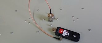
5. Of course, the module itself + antenna, as I wrote above, you can make yourself.
6. Oh yes, I almost forgot, you will need another case, otherwise what kind of device is it without a case.
As a case, we purchased the same boxes again, but in silver, for testing. I will say this, I absolutely did not like the silver color, black looks better.
When all the components are available, you can connect and program it all.
We connect to Pro Mini according to the following scheme:
Display:
RST - D6 CE - D7 DC - D5 DIN - D4 CLK - D3 VCC - 5V (optional in my case, in others 3.3V) Light - GND GND - GND
I didn't need the backlight, so I didn't connect it.
SD card:
CS-D10 MOSI-D11 MISO-D12 SCK-D13 GND - GND 5V - VCC (optional in my case, in some with a converter we connect to 3.3V)
GPS module:
RX-D8 TX-D2 GND - GND VCC-3.3 (3.3 is the limit!)
Don't forget to connect the antenna to the module, I took the power from Nano Tk. was connected for debugging, then everything will be converted to the battery.
Approximate view:
The code is simple and straightforward; to use it you will need perhaps the easiest display library. Next is the library for GPS. The rest are built-in. According to the code, the line is time*0.000001+5, essentially I brought the time into a digestible form and added a time zone. You can skip this and still get clean results.
Another nuance regarding the display library is the following: the display, including the one with the zero line, has 6 lines in total. Which is quite small, so you need to immediately decide what information to display; some will have to be displayed in symbols, saving space. The display is redrawn every second, while updating and recording information coming from satellites.
If there is a file reading error or the SD card cannot be accessed, the message SD-
, in other cases
SD+
.
Sketch
#include #include #include #include //CS-D10, MOSI-D11, MISO-D12, SCK-D13, GND - GND, 5V - VCC (optional in my case, in some, if there is no converter, we connect to 3.3V) File GPS_file; TinyGPS gps; SoftwareSerial gpsSerial(2, 8);//RX — 8 pin, TX — 2 pin static PCD8544 lcd; //RST - D6, CE - D7, DC - D5, DIN - D4, CLK - D3, VCC - 5V (optional, if there is a converter on the 3.3V line), Light - GND, GND - GND bool newdata = false; unsigned long start; long lat, lon; unsigned long time, date; void setup() { lcd.begin(84, 48); gpsSerial.begin(9600); Serial.begin(9600); pinMode(10, OUTPUT); if (!SD.begin(10)){ lcd.setCursor(0, 0); lcd.println("SD-"); return;} lcd.setCursor(0, 0); lcd.println("SD+"); GPS_file = SD.open("GPSLOG.txt", FILE_WRITE); if (GPS_file){ Serial.print("Writing to test.txt..."); GPS_file.print("LATITUDE"); GPS_file.print(“,”); GPS_file.print("LONGITUDE"); GPS_file.print(“,”); GPS_file.print("DATE"); GPS_file.print(“,”); GPS_file.print("TIME"); GPS_file.print(“,”); GPS_file.print("ALTITUDE"); GPS_file.println(); GPS_file.close(); Serial.println("done."); }else{ Serial.println("error opening test.txt"); } lcd.setCursor(0,3); lcd.print("ALT: "); lcd.setCursor(0,2); lcd.print("SPD: "); lcd.setCursor(0,4); lcd.print("LAT: "); lcd.setCursor(0,5); lcd.print("LON: "); } void loop() { if (millis() - start > 1000){ newdata = readgps(); if (newdata){ start = millis(); gps.get_position(&lat, &lon); gps.get_datetime(&date, &time); lcd.setCursor(50,1); lcd.print(date); lcd.setCursor(55,0); lcd.print(time*0.000001+5); lcd.setCursor(22, 4); lcd.print(lat); lcd.setCursor(22, 5); lcd.print(lon); lcd.setCursor(22, 2); lcd.print(gps.f_speed_kmph()); lcd.setCursor(22, 3); lcd.print(gps.f_altitude()); } } GPS_file = SD.open("GPSLOG.txt", FILE_WRITE); if(GPS_file){ GPS_file.print(lat); GPS_file.print(“,”); GPS_file.print(lon); GPS_file.print(“,”); GPS_file.print(date); GPS_file.print(“,”); GPS_file.print(time*0.000001+5); GPS_file.print(“,”); GPS_file.print(gps.f_altitude()); GPS_file.println(); GPS_file.close(); }else{ lcd.setCursor(0, 0); lcd.println("SD-"); } } bool readgps(){ while (gpsSerial.available()){ int b = gpsSerial.read(); if('\r' != b){ if (gps.encode(b)) return true;}} return false;}
After flashing the firmware, you will see something like this (in the sketch, the date output is edited to the right edge under the time):
You can play with the arrangement of the elements, there was such an option, but I realized that averaging the coordinates produces a huge error and refused.
What to do next? You can assemble everything into a case, you can use glue, you can place everything on double-sided tape, but I wanted to place everything on a breadboard:
I use LI-ion batteries as batteries. I buy batteries for action cameras in bulk and use them in my crafts, plus they can always come in handy for action cameras that I use on hikes. I bought it here.
Next comes the struggle for space, we cut off the excess from the contacts and align them with the height of the breadboard.
Using a breadboard, we put everything together:
I pasted a piece of electrical tape onto the case for the memory card, as it is in contact with the contacts of the battery charger. We flash the memory card in FAT16.
Then we launch and check, not forgetting to turn on the switch:
Adapters
An antenna adapter is used when replacing a car radio with a product of a different brand. The device allows you to reduce the difference in settings and design solutions, and also enhances the quality of searching for radio frequencies.
According to experts, purchasing an adapter is necessary:
- when the sound quality decreases, there is interference, noise, distortion in the played video and audio recordings;
- when the number of received radio stations decreases;
- when the signal in the device periodically disappears;
- when the picture on the screen of the radio or video playback device is blurry.
When selecting an adapter for a machine, you must consider:
- uniform amplitude-frequency indicators of the adapter;
- the presence of a gain of about 15-25 dB;
- sufficient height of dynamic range;
- presence of low noise figure and high gain.
The designs and dimensions of adapters for passenger cars and trucks may differ.
DIY GPS antenna
There are situations in which, without determining the location, you can find yourself in a very unenviable position. In this case, navigation devices are simply vital. Here, a weak signal from a communication satellite or its complete absence is unacceptable. Then, knowing what a GPS antenna is, you have the opportunity to make it yourself.
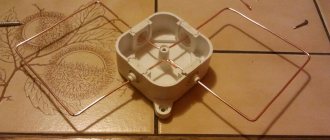
An example of a homemade GPS antenna
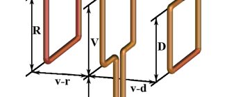
The figure below shows how you can make the necessary element from scrap materials:
- Take a wire, preferably copper, of small cross-section. In our case, 2.5 mm²;
- A square of the appropriate size is bent from the wire. The dimensions of the sides are shown in the figure;
- We attach the resulting part using soldering or electrical tape (adhesive tape) to the GPS receiver.
As a result of the manipulations performed, a signal acceptable for determining the location coordinates can be obtained.
GPS antennas are indispensable in modern GPS receivers for determining location on the ground. They are very much in demand by tourists who use these devices to correctly plot routes.
How to make an outdoor amplifier yourself
Knowing your own location is important in some cases, which is why navigation is increasingly becoming part of everyday life. Very often, users are faced with a weak GPS signal when it is needed, or even its complete absence. A way out of this situation could be a self-made antenna for any device with a GPS module.
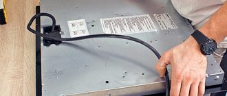
A device of Chinese origin with a GPS module often suffers from a lack of signal; The reason is a weak signal receiving module. The antenna is operated by a patch located on the outside of the device. It should be noted that this device works outdoors, but the signal disappears if poor reception conditions are created (bring the device into the house, put it in the car). Procedure:
- We determine how difficult or easy it is to get to the GPS module;
- We take copper wire with a cross section of 5/2 millimeters square, a length of 46 millimeters * 4, where 4 are the sides of the square, it represents a square;
- We make a regular square from the wire, use pliers, we need to keep the dimensions exactly, how the antenna will work depends on this;
- Solder the antenna to the external GPS patch.
For convenience, the antenna can be attached to the device body with tape. The result of the work performed is stable signal reception by the device indoors and in the car.
An example of a homemade GPS antenna makes it possible to receive a signal even in bad weather conditions and inside the car. Travel enthusiasts often use navigation when they need to plot a short route from one point to another. An outdoor GPS antenna guarantees stable signal reception.
Operation setup and connection
After installing the GPS antenna, you need to connect and configure the device. Connects connections with external sources and control wire with marking code AMP-CON. The gray cable with the letter BRAKE regulates the disconnection from watching TV and DVD programs when the car is moving.
You can do the setup work yourself according to the instructions from the manufacturer, which contains software support for the model (OZI, Navitel, IGO). The necessary programs are recorded on the SD card. The IGO8 system requires setting the resolution for the radio to at least 480x234 px.
Then the map is inserted into the device, and the “Options” section is selected in the main GPS menu. In the settings, the required program is selected, the path to the SD card is indicated, and the navigation program is turned on. After testing the settings and operation of the device, the device will determine the location based on geographic coordinates and allow you to connect radio or video
We repair and restore equipment
Service center in Kyiv
Connecting an external GPS antenna to a navigator, tablet, smartphone, laptop
installation of an additional external GPS antenna module (with a 3 meter cable)
Connecting gadgets
Modern gadgets have a built-in GPS antenna. However, they cannot always be used as navigators. Not in all unfavorable conditions they can pick up a signal from the nearest communication satellite. Such unfavorable conditions include:
- Car windows with a coating that interferes with the free passage of signals;
- The size of the gadget screen does not always allow you to clearly see all the details of the route;
- The overall dimensions of the tablets do not allow it to be placed under the windshield of a car.
When going to a store to purchase the necessary device, it is necessary to explain in great detail to the sales consultant the type of gadget for which the antenna is being purchased, for what purposes the device is planned to be used, as well as what result of use is required, where it will need to be installed.
All this must be taken into account because today's amplifiers use such modern means of communication as a USB port and Bluetooth. For use in gadgets, the latest encrypted data transfer protocol is preferable, because does not imply the need for additional wires that interfere with its use, for example, with a smartphone. However, with this connection it is necessary to very accurately install the antenna in the required location. Computers usually use special USB connectors.
GPS in the car
A modern car requires a navigator built into the on-board computer. Navigation is very convenient for any driver to use.
Car navigator
Designers involved in the design of car navigation systems settled on the following operating algorithm:
- An external type device receives and amplifies the signal coming from the satellite. In an enhanced form, it ends up in the navigator;
- The received signal appears in the navigation receiver. Based on this, the location of the vehicle is determined. Next, the coordinates are clarified using the system control unit;
- After specifying the coordinates of the vehicle's location, the optimal route to the final destination is calculated. This happens on the basis of road maps loaded during the production of the machine. The navigation system is often controlled by voice. If it is necessary to update maps loaded into the car’s memory, use special boot DVDs;
- The correct direction of movement is determined using the parameters of the angular velocity of the wheels, which is calculated by the on-board computer.
When setting up a vehicle location on a map loaded into its memory, the vehicle must be at static rest and in the location indicated on the map. In this case, the GPS antenna for the navigation unit is installed at the factory.
How does it work
The device receives a signal from the nearest communication satellite. Reception accuracy depends on the correct choice of characteristics. If the parameters are set incorrectly, the gadget will not work correctly in rain and snow. When the device receives a signal from a satellite, it is amplified and transmitted to the navigator. Then the coordinates are specified through the control unit. Based on the data obtained, the device calculates the optimal route for a car or pedestrian.
Sensors are now built into all smartphones, tablets, car radios, and Starline alarm systems. However, they do not always determine the location correctly - due to slow software operation, lack of satellites, or poor-quality antenna device.
If there is a connector for connection, it is possible to purchase a finished product at an electronics store. If there is no split hole, you will have to modify the device or make the navigator yourself.
Types of antennas for radio tape recorders
Today there are many devices for improving the signal, the best of them are car antennas, which can be:
External. Such devices are used to receive television and radio signals. A TV antenna for a car radio is a passive device that is exposed to the environment, but it has a fairly high sensitivity. Because of this, it is necessary to equip the antenna with an additional signal amplifier (adapter). In addition, many note the inconvenience of installing an external device on the car body.
Internal. Devices of this type are active GPS antennas, which are usually mounted on the windshield of a car. The device is equipped with a built-in amplifier and can be used with a wide variety of radio models.
GPS modules are very popular among car enthusiasts. The operating principle of such antennas is to receive satellite signals, convert them into an intermediate frequency and subsequent processing. Internal antennas are connected to the vehicle's on-board system. The main advantages of such devices are: small size, ease of installation, “confident” signal level and long service life. Among the disadvantages, it is worth noting only the rather high cost of such antennas.
When choosing an antenna for a radio, you need to take into account many characteristics, including signal reception range, device power and much more. The place where you plan to install the device is also important.
Types and principles of operation of antennas
Antennas pick up electromagnetic waves that travel everywhere. A weak electromotive force of alternating radio frequency current is induced in the antenna conductor. It is sent to the receiving device. After this, amplification, detection and selection of the required information occurs.
Antennas are divided into active and passive. The first ones are distinguished by the presence of an amplifier that increases the signal from the car antenna. Active receiving devices provide stable reception of radio stations at a distance of more than 60 km from the transmitter.
Passive antennas do not have an amplifier. They are easier to assemble with your own hands. A passive car antenna is most often installed on the roof of a vehicle and provides reliable signal reception at a distance of up to 15 km, for example, within city limits.
Are you a car driver?! Then you can take this simple test and find out. Go to test »