Design and features
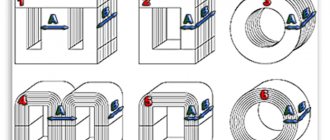
The main design difference between the armored transformer (BT) and other single-phase transformers can be easily seen in Figure 1, b.
Rice. 1 – Schemes of single-phase transformers
Figures 1a and 1c show rod (ST) and toroidal (TT), respectively. The CT design scheme is opposite to the BT scheme in terms of the location of the main elements relative to each other, and in the first it is the other way around - the core is covered by windings. The BT, in comparison with the ST, has fewer outputs for the same number of windings, since the primary winding of the ST must be distributed in two equal parts between the magnetic conductor rods.
In this regard, in certain cases with CT there are difficulties in placing the leads, however, if the core is detachable tape, then the CT will even have an advantage, manifested in the ability to provide a small gap in the core and tighten its two halves.
Characteristic
The mere presence of such parts leads to an increase in weight and volume. The armored design to some extent reduces the dimensions of the BT, while the side yokes serve as protection against mechanical stress for the windings. This is extremely important, given the small dimensions, the absence of a casing and the location together with other equipment on the circuit, and not separately. The TT has the smallest number of elements, which means its dimensions are least susceptible to growth, but at the same time it is also structurally the least technologically advanced.
Technological disadvantages are expressed, firstly, in the need for sequential production of the core and coils (lengthening the production cycle), and secondly, in low productivity during winding of the latter.
In addition to this, the toroidal winding machine is significantly more complex and expensive compared to conventional line winding machines, and cannot be used for winding wire whose diameter exceeds 2 mm. This narrows the scope of CT application at high powers, while at very low powers the core window may not be enough to pass the shuttle. It is especially difficult to wind CTs at a given frequency of 50 Hz, when a lot of turns are needed.
Against the background of the above, another significant advantage of BT appears - it is the most technologically advanced solution in conditions of low power, with stamped cores. Moreover, its superiority in relation to CT is also weighty - only one coil is required, not two. In general, the difference between two coils and one always comes to the fore when small-sized transformers are required.
Principle of operation
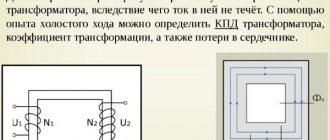
Any single-phase transformer operates on the principle of transmitting from the input (primary winding) to the output (output contacts of the secondary winding) a complete repetition of the input voltage in terms of the ratio of turns in the secondary and primary windings. By applying voltage U1 to the primary and connecting the secondary to the load, we obtain currents I1 and I2 in each, respectively. These currents will generate magnetic fluxes F1 and F2 directed towards each other. The total magnetic flux in the magnetic circuit will decrease, as a result of which the emf E1 and E2 induced by it will decrease.
U1 will remain the same, and a decrease in E1 will cause an increase in I1. With an increase in I1, F1 will increase until the demagnetizing effect of F2 is compensated. Equilibrium is restored when the total flow reaches its previous value.
Types
In operating condition, the transformer core is constantly exposed to an alternating magnetic field, which causes the formation of eddy currents around it. This leads to heating of the magnetic circuit, which means useful energy is wasted. The percentage of losses depends on:
- core material;
- frequency response of magnetization reversal;
- maximum magnetic induction.
The easier it is to magnetize a metal, the easier it is to remagnetize with a mutual reduction in losses. Therefore, the cores are made from steel with pronounced magnetic properties. The phenomenon of eddy currents in monolithic conductors is gaining maximum momentum, since the material is endowed with low resistance. To reduce losses associated with this, this resistance is increased by assembling a magnetic circuit from steel sheets not exceeding 0.5 mm in thickness, with insulation in the form of varnish and scale. The insulating layer does not allow eddy currents to affect the magnetic flux in the core, which has a positive effect on losses. Assembly is carried out using one of two technologies:
- end-to-end - the core itself is assembled, then windings are placed on it, at the final stage everything is fastened together with a yoke (a simpler method, but losses are higher);
- interlacing (lamping) - the plates of each next row overlap the joints of the previous one (greater demand due to lower losses).
The geometry and type of magnetic circuit determine the typical differences between transformers. The type of magnetic circuit can be tape or plate. In turn, its shape gives the name and designation: armored magnetic cores are made W-shaped and are designated by the letter Ш, rod ones are U-shaped and P, ring ones are O-shaped and O, three-phase magnetic cores are made E-shaped, and orthogonal ones are designated three letters OPL. For tape magnetic cores, the letter L is added to the designation, for example, ШЛ, PL, OL, EL.
Thus, the armored transformer can be type Sh or ShL.
Sh
The most common type of BT. The middle rod with the general flow passing through it is closed by two outer rods. The cross-section of the outer rods is equal to half the cross-section of the middle one.
SHL
Tape (twisted) armor magnetic cores ШЛ also have the following subtypes:
- ShLM – with a reduced I1/I ratio;
- SHLO – with an extended window;
- ShLP – with an increased B/l ratio;
Non-standardized magnetic cores
| Type of magnetic circuit | Geometric dimensions, mm. | Weight, kg. | EMF, V/vit. | lsr, see | Scm, cm2 | H, A/cm. | B, Tl. | ||||||
| A | WITH | IN | h | WITH | N | R | |||||||
| AZZ | 10,5 -0,8 | 11 | 40 +1,0 | 33 | 33 | 56 | 1,5 | 0,37 | 0,141 | 12,0 | 3,84 | 3,6 | 1,65 |
| A44 | 10,5 -0,8 | 22,7 | 40 +1,0 | 33 | 44 | 56 | 1,5 | 0,45 | 0,141 | 13,75 | 3,84 | 4,0 | 1,65 |
| A77 | 22,5 -0,8 | 30 | 40 +1,0 | 123 | 77 | 171 | 2,0 | 2,5 | 0,322 | 37,6 | 8,5 | 3,0 | 1,7 |
| A80 | 23,2 -0,8 | 30 | 40 +1,0 | 123 | 80 | 174 | 2,0 | 2,55 | 0,339 | 38,0 | 9,0 | 3,0 | 1,7 |
| A80a | 23,2 -0,8 | 30 | 40 +1,0 | 78 | 80 | 127 | 2,0 | 1,94 | 0,339 | 28,6 | 9,0 | 3,0 | 1,7 |
| A80b | 23,2 -0,8 | 30 | 40 +1,0 | 55 | 80 | 104 | 2,0 | 1,65 | 0,339 | 24,0 | 9,0 | 3,0 | 1,7 |
| A88 | 28,0 -0,8 | 30 | 40 +1,0 | 78 | 88 | 136 | 3,0 | 2,5 | 0,398 | 30,4 | 10,6 | 2,25 | 1,7 |
| A92 | 30,0 -1,0 | 30 | 40 +1,0 | 123 | 92 | 189 | 3,0 | 3,6 | 0,433 | 40,0 | 11,5 | 2,8 | 1,7 |
| A99 | 33,0 -1,0 | 30 | 40 +1,0 | 123 | 99 | 195 | 3,0 | 4,0 | 0,468 | 41,0 | 12,5 | 2,7 | 1,7 |
| A107 | 22,5 -0,8 | 60 | 40 +1,0 | 123 | 107 | 171 | 3,0 | 2,85 | 0,322 | 43,7 | 8,5 | 3,0 | 1,7 |
| A124 | 46,0 -1,0 | 30 | 40 +1,0 | 123 | 124 | 218 | 3,0 | 6,0 | 0,655 | 45,0 | 17,3 | 1,9 | 1,7 |
| A128 | 48,0 -1,0 | 30 | 40 +1,0 | 123 | 128 | 222 | 3,0 | 6,3 | 0,690 | 45,6 | 18,24 | 2,0 | 1,7 |
| A128a | 48,0 -1,0 | 30 | 40 +1,0 | 78 | 128 | 177 | 3,0 | 5,1 | 0,690 | 36,6 | 18,24 | 2,1 | 1,7 |
| A128b | 48,0 -1,0 | 30 | 40 +1,0 | 55 | 128 | 154 | 3,0 | 4,5 | 0,690 | 32,1 | 18,24 | 2,1 | 1,7 |
| A134 | 51,5 -1,0 | 30 | 40 +1,0 | 123 | 134 | 220 | 3,0 | 7,1 | 0,743 | 46,7 | 19,6 | 1,9 | 1,7 |
| A154 | 46,0 -1,0 | 60 | 40 +1,0 | 123 | 154 | 225 | 3,0 | 6,81 | 0,655 | 51,0 | 17,3 | 2,0 | 1,7 |
| A158 | 48,0 -1,0 | 60 | 40 +1,0 | 123 | 158 | 230 | 3,0 | 7,3 | 0,690 | 51,6 | 18,2 | 2,0 | 1,7 |
| A158a | 48,0 -1,0 | 62 | 40 +1,0 | 79,5 | 159 | 179 | 3,0 | 6,1 | 0,690 | 42,6 | 18,2 | 2,2 | 1,7 |
| A158b | 48,0 -1,0 | 60 | 40 +1,0 | 55 | 158 | 154 | 3,0 | 5,4 | 0,690 | 38,0 | 18,2 | 2,25 | 1,7 |
| B35 | 10,5 -0,8 | 12,5 | 32 +1,0 | 85 | 35 | 108 | 2,0 | 0,56 | 0,118 | 22,8 | 3,12 | 3,6 | 1,7 |
| B47 | 10,5 -0,8 | 25 | 32 +0,5 | 85 | 47 | 108 | 2,0 | 0,62 | 0,118 | 25,3 | 3,12 | 4,6 | 1,7 |
| B69 | 21,5 -1,0 | 25 | 32 +0,5 | 85 | 69 | 130 | 2,0 | 1,47 | 0,241 | 28,8 | 6,35 | 3,4 | 1,7 |
| B112 | 25,0 -1,0 | 60 | 32 +0,5 | 55 | 112 | 110 | 3,0 | 1,82 | 0,286 | 31,0 | 7,5 | 2,8 | 1,7 |
| B43 | 13,0 -1,0 | 16,5 | 25 +0,6 | 41,5 | 43 | 69 | 2,0 | 0,39 | 0,124 | 15,7 | 3,0 | 6,7 | 1,85 |
| G25 | 8,0 -0,4 | 8 | 20 +0,6 | 24,5 | 25 | 42 | 1,0 | 0,11 | 0,058 | 9,0 | 1,5 | 5,3 | 1,7 |
| L40 | 10,2 -0,5 | 20 | 16 +0,6 | 57 | 41 | 78 | 1,5 | 0,214 | 0,057 | 18,5 | 1,53 | 4,5 | 1,7 |
| H85 | 26,0 -1,0 | 33 | 50 +1,0 | 100 | 86 | 155 | 3,0 | 3,3 | 0,468 | 34,8 | 12,25 | 3,0 | 1,7 |
| H93 | 30,0 -1,0 | 33 | 50 +1,0 | 100 | 94 | 163 | 3,0 | 3,97 | 0,538 | 36,0 | 14,2 | 2,4 | 1,7 |
| H103 | 26,0 -1,0 | 50 | 50 +1,0 | 110 | 103 | 170 | 3,0 | 3,84 | 0,462 | 40,2 | 12,2 | 2,55 | 1,7 |
| H112 | 31,0 -1,0 | 50 | 50 +1,0 | 110 | 113 | 178 | 3 | 4,75 | 0,544 | 41,7 | 14,6 | 3,0 | 1,7 |
| H112a | 31,0 -1,0 | 60 | 50 +1,0 | 110 | 123 | 178 | 3,0 | 5,0 | 0,544 | 43,7 | 14,6 | 3,0 | 1,7 |
| H123 | 36,0 -1,0 | 50 | 50 +1,0 | 110 | 123 | 188 | 3,0 | 5,7 | 0,643 | 43,3 | 17,0 | 3,0 | 1,7 |
| H132 | 40,0 -1,0 | 50 | 50 +1,0 | 110 | 132 | 191 | 3,0 | 6,6 | 0,713 | 44,5 | 19,0 | 3,0 | 1,7 |
| H163 | 50,0 -1,0 | 60 | 50 +1,0 | 123 | 163 | 226 | 3,0 | 9,7 | 0,900 | 52,3 | 23,8 | 2,6 | 1,7 |
| PITCHER,000 | 10,0 -0,9 | 12 | 30 + 0,65 | 29,8 | 32,5 | 51,8 | 1,0 | 0,256 | 0,095 | 11,5 | 2,75 | 4,5 | 1,56 |
| KBSHU,004 | 13,2 -0,5 | 12,4 | 13 +0,6 | 39,5 | 39,2 | 66,7 | 1,5 | 0,19 | 0,057 | 14,5 | 1,6 | 3,5 | 1,7 |
| KVSHU,005 | 13,2 -0,5 | 12,4 | 20 +0,6 | 39,5 | 39,2 | 66,7 | 1,5 | 0,28 | 0,091 | 14,5 | 2,43 | 3,5 | 1,7 |
| PL 50×50-150 | 50,0 -1,0 | 75,5 | 50 +1,0 | 150 | 177 | 253 | 3,0 | 11,2 | 0,900 | 60,8 | 23,8 | 2,5 | 1,7 |
| PL 60×50-150 | 60,0 -1,2 | 75,5 | 50 +1,0 | 150 | 197 | 273 | 2,5 | 14,1 | 1,040 | 64,0 | 28,0 | 2,0 | 1,7 |
| PL 50×50-200 | 50,0 -1,0 | 75,5 | 50 +1,0 | 200 | 177 | 303 | 3,0 | 13,0 | 0,900 | 70,8 | 23,8 | 2,0 | 1,7 |
Purpose and application
Armored transformers are not labor-intensive and cheap to manufacture, and for signal small/medium power (up to 100 W) transformers, the armored type is usually chosen. BT, however, are also the most sensitive to interference, and they also have a large leakage inductance. The ShL and ShLM series are used when the smallest weight, rated power of no more than 100 W and a frequency of 400 Hz (ShL) or 50 Hz (ShLM) are needed. The ShLO series is used in low voltage conditions at frequencies from 1 to 5 kHz and high voltages at frequencies from 50 Hz to 5 kHz.
The Soviet tape small-sized low-power transformer - TPP - is distinguished by low voltages on the secondary windings. TPPs perform well in circuits of household appliances, in radio-electronic and communication devices, and computer systems powered by industrial and special networks with alternating current at voltages of 40, 115, 127 and 220 V and a frequency of 50 or 400 Hz. They are characterized by a wide range of voltages and currents with a power of up to 500 VA.
Technical data
Serially produced tape magnetic cores type ShL, ShLM made of cold-rolled steel grade 3406-08 GOST 21427.1-83 with a thickness of 0.35 mm
| Magnetic cores ШЛ | Magnetic cores ShLM |
| SHL 6x12.5 | ShLM 10x20 |
| SHL 8x12.5 | ShLM 10x25 |
| ShL 8x16 | ShLM 12x16 |
| SHL 10x12.5 | ShLM 12x25 |
| ShL 10x16 | ShLM 16x25 |
| SHL 10x20 | ShLM 16x32 |
| SHL 12x16 | ShLM 20x16 |
| ШЛ 12x20 | ShLM 20x20 |
| ShL 16x16 | ShLM 20x25 |
| ШЛ 16х20 | ShLM 20x32 |
| SHL 16x25 | ShLM 25x32 |
| ShL 16x32 | ShLM 25x40 |
| ShL 20x25 | |
| ШЛ 20х40 | |
| ШЛ 25х40 | |
| ШЛ 25х50 | |
| ШЛ 32х40 | |
| ШЛ 32х50 | |
| SHL 40x40 | |
| SHL 40x50 | |
| ШЛ 20х50х85 |
Serially produced tape magnetic cores type ShL, ShLM made of cold-rolled steel grade 3425 TO-ET GOST 21427.4-78 with a thickness of 0.08 mm
| Magnetic cores ШЛ | Magnetic cores ShLM |
| SHL 4x6.5 | ShLM 8x10 |
| ShL 4x10 | ShLM 8x12.5 |
| SHL 5x5 | ShLM 10x10 |
| ShL 5x8 | ShLM 10x12.5 |
| ShL 5x10 | ShLM 10x20 |
| SHL 6x6.5 | ShLM 12x12.5 |
| SHL 6x8 | ShLM 12x16 |
| ShL 6x10 | ShLM 16x16 |
| SHL 6x12.5 | ShLM 16x25 |
| SHL 8x8 | ShLM 16x32 |
| SHL 8x10 | ShLM 20x25 |
| SHL 8x12.5 | ShLM 20x32 |
| ShL 8x16 | ShLM 25x32 |
| SHL 10x10 | ShLM 25x40 |
| SHL 10x12.5 | |
| ShL 10x16 | |
| SHL 10x20 | |
| SHL 12x16 | |
| ШЛ 12x20 | |
| ShL 20x25 | |
| ШЛ 20х32 | |
| ShL 16x16 | |
| ШЛ 16х20 | |
| SHL 16x25 | |
| ShL 16x32 |
How to calculate
Almost any calculations must begin with core measurements. Figures 2, c and 3 show the quantities that need to be measured at the BT in a schematic and visual display, respectively.
Rice. 2 – Measurement of core dimensions according to the diagram.
Rice. 3 – Measuring the dimensions of the core by appearance.
Secondary power
P2 = 2 * Pgab – P1,
where Pgab is the overall power (W), P1 is the power of the primary winding (W).
Overall power
Pgab = (n * Sc * So * 4.44 * f * B * j * Km * Ks) / ((1 + n) * 100),
where n is the tabulated efficiency of the transformer, Sc is the cross-sectional area of the magnetic core (cm²), So is the cross-sectional area of the window (cm²), f is the frequency (equal to 50 Hz), B is the magnetic induction (T), j is the tabulated current density in coil wires (A/mm2), Km – coefficient of filling of the magnetic circuit window with copper, Kс –…steel.
Actual steel section
Sc = a * b,
where a is the width of the rod, b is the thickness of the magnetic circuit according to Figure 2 or 3.
Actual cross-sectional area of the core window
So = h * c,
where h is the height of the window, c is the width of the window according to Figure 2 or 3.
The value of the rated current of the primary winding
P1 = U1 * I1
where I1 is the current in the primary winding (A).
Rated current in windings
I = Spr * j,
where Spr – wire cross-section (mm²).
Winding wire cross-section
Spr = 3.14 * R²,
where I is the current in the winding (A), R is the radius of the wire (mm).
Diameter of winding wires without insulation
d = 2 * √ (I / (3.14 * j))
Number of turns of each winding
W1 = U1 / u1
W2 = U2 / u2,
where W1 is the number of turns of the primary, W2 - ...secondary, U1 - the value of the input voltage on the primary (V), U2 - the output voltage on the secondary (V), u1 - the value of the voltage on one turn of the primary (V), u2 - ... the secondary (V ).
Number of turns per volt
w1 = W1 / U1
w2 = W2 / U2
For the same wire we have the same values in both windings, that is:
w1=w2
The maximum power that the magnetic circuit can provide
Pmax = Sc²
Magnetic cores according to international standards
| Type of magnetic circuit | Geometric dimensions, mm. | Weight, kg. | EMF, V/vit. | lsr, see | Scm, cm2 | H, A/cm. | B, Tl. | ||||||
| A | WITH | IN | h | WITH | N | R | |||||||
| UI 30/10 | 9,5 -0,5 | 10,2 | 10 +0,6 | 30 | 30 | 50 | 1,5 | 0,076 | 0,03 | 11,0 | 0,9 | 4,6 | 1,5 |
| UI 30/16 | 9,5 -0,5 | 10,2 | 16 +0,6 | 30 | 30 | 50 | 1,5 | 0,121 | 0,047 | 11,0 | 1,43 | 4,6 | 1,5 |
| UI 39/13 | 12,7 -0,5 | 12,8 | 13 +0,6 | 39,1 | 38,6 | 65,4 | 1,5 | 0,19 | 0,057 | 14,4 | 1,54 | 3,4 | 1,7 |
| UI 39/16 | 12,7 -0,5 | 12,8 | 16 +0,6 | 39,1 | 38,6 | 65,4 | 1,5 | 0,23 | 0,071 | 14,4 | 1,9 | 3,4 | 1,7 |
| UI 39/20 | 12,7 -0,5 | 12,8 | 20 +0,6 | 39,1 | 38,6 | 65,4 | 1,5 | 0,32 | 0,088 | 14,4 | 2,4 | 3,4 | 1,7 |
| U25 | 10,3 -0,8 | 19,0 | 25 +1,0 | 57,2 | 40,1 | 79,4 | 2,0 | 0,34 | 0,087 | 18,5 | 2,37 | 2,9 | 1,65 |
| U32 | 10,3 -0,8 | 19,0 | 32 +0,5 | 57,2 | 40,1 | 79,4 | 2,0 | 0,43 | 0,11 | 18,5 | 3,0 | 2,9 | 1,65 |
| U38 | 10,3 -0,8 | 19,0 | 38 +0,9 | 57,2 | 40,1 | 79,4 | 2,0 | 0,52 | 0,13 | 18,5 | 3,6 | 2,9 | 1,65 |
| Q13 | 8,7 -0,8 | 12,7 | 13 +0,5 | 38,1 | 30,6 | 56,4 | 1,5 | 0,106 | 0,036 | 12,9 | 1,0 | 3,25 | 1,5 |
| Q25 | 8,7 -0,8 | 12,7 | 25 +1,0 | 38,1 | 30,6 | 56,4 | 1,5 | 0,206 | 0,072 | 12,9 | 2,0 | 3,25 | 1,5 |
| Q38 | 8,7 -0,8 | 12,7 | 38 +0,9 | 38,1 | 30,6 | 56,4 | 1,5 | 0,31 | 0,108 | 12,9 | 3,1 | 3,25 | 1,5 |
| T25 | 10,3 -0,8 | 15,9 | 25 +1,0 | 50,8 | 36,9 | 73,0 | 1,5 | 0,31 | 0,087 | 16,6 | 2,4 | 3,0 | 1,6 |
| T32 | 10,3 -0,8 | 15,9 | 32 +0,5 | 50,8 | 36,9 | 73,0 | 1,5 | 0,39 | 0,108 | 16,6 | 3,0 | 3,0 | 1,6 |
| V38 | 13,5 -0,8 | 22,2 | 38 +0,9 | 63,5 | 49,6 | 92,1 | 3,0 | 0,78 | 0,174 | 21,4 | 4,7 | 2,7 | 1,7 |
| V51 | 13,5 -0,8 | 22,2 | 50 +1,0 | 63,5 | 49,6 | 92,1 | 3,0 | 1,03 | 0,234 | 21,4 | 6,2 | 2,7 | 1,7 |
| X38 | 16,7 -0,8 | 28,6 | 38 +0,9 | 76,2 | 62,3 | 111,1 | 3,0 | 1,2 | 0,218 | 26,2 | 5,8 | 2,6 | 1,7 |
| X51 | 16,7 -0,8 | 28,6 | 50 +1,0 | 76,2 | 62,3 | 111,1 | 3,0 | 1,58 | 0,292 | 26,2 | 7,7 | 2,6 | 1,7 |
| Z25 | 19,8 -0,8 | 34,9 | 25 +1,0 | 88,9 | 75,0 | 130,2 | 3,0 | 1,12 | 0,174 | 31,0 | 4,6 | 2,5 | 1,7 |
| Z70 | 19,8 -0,8 | 34,9 | 70 +1,4 | 88,9 | 75,0 | 130,2 | 3,0 | 3,15 | 0,48 | 31,0 | 12,8 | 2,5 | 1,7 |
Checking a step-down transformer with a multimeter
Let's say a 4-pin transformer - two wires from the primary winding and two from the secondary. Checking it comes down to identifying damage in the windings. To determine whether there are any, first we’ll switch the multimeter to diode testing mode or move the switch to the resistance scale. Then we check one coil, without paying attention to the polarity of connecting the probes, since in this case it is absolutely not important. We do the same with the second one.
Low ohmmeter readings will indicate the serviceability of the windings; lack of tester response will indicate the opposite.
If the affiliation of a particular contact to any of the windings is not known, then it is established during the testing process - the resistance in the primary of the step-down transformer should be slightly higher.