Good afternoon, electrical experts!
My name is Sasha, and this question torments me. Today on the Internet you can dig up a bunch of material on the topic of how “Mother Earth” is able to provide us with free electricity, and the scoundrels oil and nuclear workers (monopolists) do not allow the development of technology, since this could turn the whole world upside down.In general, have you heard anything about whether the Earth's electric and magnetic fields can become a source of cheap electricity? Thank you for your attention!
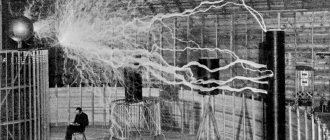
Tesla coil in action
Myths and reality
There are a large number of videos on the Internet where people light 150 W lamps from the ground, start electric motors, and so on. There are even more different text materials that tell in detail about earth batteries. It is not recommended to take such information too seriously, because you can write anything, but carry out the appropriate preparation before shooting a video.
After viewing or reading these materials, you can really believe in various fables. For example, that the electric or magnetic field of the Earth contains an ocean of free electricity, which is quite easy to obtain. The truth is that the energy reserve is truly enormous, but extracting it is not at all easy. Otherwise, no one would use internal combustion engines, heat themselves with natural gas, and so on.
For reference. Our planet’s magnetic field really exists and protects all living things from the harmful effects of various particles coming from the Sun. The field lines of this field run parallel to the surface from west to east.
If, in accordance with the theory, we conduct a certain virtual experiment, we can see how difficult it is to obtain electricity from the earth’s magnetic field. Let's take 2 metal electrodes, for the purity of the experiment - in the form of square sheets with sides of 1 m. We will install one sheet on the surface of the earth perpendicular to the lines of force, and raise the second to a height of 500 m and orient it in space in the same way.
Theoretically, a potential difference of about 80 volts will arise between the electrodes. The same effect will be observed if the second sheet is placed underground, at the bottom of the deepest shaft. Now imagine such a power plant – a kilometer high, with a huge surface area of the electrodes. In addition, the station must withstand lightning strikes, which will definitely strike it. Perhaps this is the reality of the distant future.
Nevertheless, it is quite possible to obtain electricity from the ground, albeit in tiny quantities. It can be enough to light an LED flashlight, turn on a calculator, or charge your cell phone a little. Let's look at ways to do this.
Atmospheric energy potential
The Earth's atmosphere has enormous potential resources. In the gap between its surface and the boundary of the ionosphere, the potential difference can reach 300 thousand volts. The electric field strength directly near the surface can reach up to 150 volts per 1 meter. This value gradually decreases with increasing altitude. For example, at a distance of 30 kilometers the voltage drops to 1 volt per meter.
Reaching the ionosphere, the electric field strength tends to zero, since the conductivity of this medium increases significantly under the influence of ionization. Ionization itself is caused by solar radiation.
A person regularly feels the impact of accumulated electrical charges. For example, when leaving a car and touching the body, you can feel a static discharge. It accumulates due to car tires acting as an insulator and preventing current from flowing to the ground. Through the human body, electricity from the body goes into the ground, accompanied by a small spark and a slight electric shock.
Many dreamed of taming the energy of a lightning discharge. However, such free electricity comes with enormous technical difficulties, mainly due to the short-term and variable effects of lightning. In addition, a powerful discharge needs to be captured and transported to a special storage device that has not yet been invented. One should also take into account the fact that the location of a lightning strike cannot be predicted in advance, and the high power of the discharge cannot be controlled and controlled, that is, normal power supply is impossible.
Electricity from two rods
This method is based on a completely different theory and has nothing to do with the Earth’s magnetic or electric field. And this theory is about the interaction of galvanic pairs in a saline solution. If you take two rods of different metals and immerse them in such a solution (electrolyte), a potential difference will appear at the ends. Its value depends on many factors: composition, saturation and temperature of the electrolyte, size of the electrodes, immersion depth, and so on.
Such generation of electricity is also possible through the ground. We take 2 rods from different metals, forming a so-called galvanic pair: aluminum and copper. We immerse them in the ground to a depth of approximately half a meter, keeping the distance between the electrodes small, 20-30 cm is enough. We water the area of land between them generously with saline solution and after 5-10 minutes we take measurements with an electronic voltmeter. The meter readings may vary, but at best you will get 3V.
Note. The voltmeter readings depend on the soil moisture, its natural salt content, the size of the rods and the depth of their immersion.
In fact, everything is simple, the resulting free electricity is the result of the interaction of a galvanic couple, in which moist earth served as an electrolyte, the principle is similar to the operation of a salt battery. A real experiment about the potential difference across electrodes driven into the ground can be seen in the video:
Grounding device in a private house
The grounding scheme for a private house includes: an electrical appliance, a distribution panel with a PE bus, a grounding conductor, and a ground electrode.
According to the PUE clause 1.7.70, various structures suitable for these purposes can be used as grounding conductors. First of all, you can use natural grounding agents, which can become:
- Water supply and other metal pipelines laid in the ground, connected at joints by gas or electric welding, with the exception of pipelines of flammable liquids, flammable and explosive gases and mixtures, sewerage and central heating;
- Well pipes;
- Metal and reinforced concrete structures of the house in contact with the ground.
If there are natural grounding conductors, it is necessary to make a tap, that is, lay a grounding conductor, from these structures to the PE bus in the power panel. The removal is carried out using welding and bolting. We weld a steel strip and a bolt to the natural grounding conductor, and connect a copper wire to it through a bolted connection.
Note:
If pipes are used as natural grounding conductors, their service life is reduced due to the flow of leakage currents through them. Therefore, I would recommend making a separate grounding loop using artificial ground electrodes.
If there are no natural grounding conductors or the house structure is wooden, then an artificial grounding conductor must be installed.
For artificial grounding electrodes, according to the latest requirements, a round steel billet with a diameter of at least 16 mm is used, or a steel corner measuring 50x50x5 mm and a length of 2.5–3.5 m can be used. They are driven vertically into a trench 0.70 m deep, leaving 10 cm above the surface. Grounding electrodes connected to each other along the entire contour, laid in a trench with strip steel with a cross section of 4x40 mm or round steel with a diameter of 10–16 mm. The connections will be made by welding.
The grounding circuit is connected to the PE bus with a grounding copper conductor with a cross-section of at least 2.5 mm 2, but not more than the cross-section of the phase wires, strip steel with a cross-section of at least 48 mm 2 and a thickness of at least 4 mm, a steel angle with a shelf thickness of at least 2.5 mm. All connections are made via bolt or welding. This way we ensure not only the continuity of the connection, but also the necessary contact area. The ground loop connection diagram is shown in Fig. 4
Figure 4. Ground loop in a private house
If the farm has a utility room where several power receivers are installed, for example, lathes, and they are powered by a four- or two-wire cable, then such equipment must be grounded.
We will create an internal grounding loop around the perimeter of the room. The internal grounding loop is made of a steel strip with a cross-section of at least 24 mm2 and a thickness of at least 3 mm at a height of at least 0.8 m from the floor level. We connect the grounding screw on the equipment case to the internal grounding loop of the room with a 20x5 mm steel strip or a copper wire of at least 2.5 mm2. The internal grounding loop, in turn, is connected to grounding conductors (at least at two points).
Example of work on grounding installation
Calculations and design are made for the installation of a grounding loop. The entire range of solutions for grounding your home must be carried out according to calculations and design. Installing a grounding loop is a very difficult task. It will be necessary to carry out a large amount of excavation work, carry out measurements and calculations of the electrical resistance of the soil on the land plot, and involve welding. Usually such work is entrusted to specialists, but you can do it yourself. To save materials and physical effort, it is better to perform a grounding loop near the grounded input power distribution panel. When making a grounding device you will need:
- Three pieces of three-meter steel angle (50x50x5 mm) or three steel rods with a diameter of at least 16 mm, providing the required resistance depending on the resistivity of the soil;
- 9 meters of steel strip (4x40 mm);
- steel strip from the input power distribution panel to the ground loop.
- We dig a trench 0.5 meters wide and 0.7 meters deep, connecting the house with the proposed location of the ground loop. The trench ends in an equilateral triangle 3x3x3 meters.
- In the corners of the triangle you need to drill 3 wells approximately 3 meters deep and drive 3 corners of 3 meters into them. If the soil in the area is soft, you can use a sledgehammer. One end of the angle needs to be sharpened on a sharpener, and a pad must be welded to the other, and with such tricks it is easy to hammer the angle 3 meters. We leave a 0.01 meter corner above the bottom of the trench and weld a steel strip to the corners around the perimeter. This will be the grounding source.
- We lay a steel strip from the ground loop along the bottom of the trench to the house. We attach one side of the strip by welding to the grounding loop, and the other to the grounding bus or the grounding screw of the input power distribution panel.
- We bury the finished structure in a trench with homogeneous soil. The soil should not contain crushed stone and construction waste. To reduce the resistance of the grounding device, metal fence posts or metal supports can be connected to the ground loop circuit. To connect the ground loop we use lap welding. Welding areas are coated with bitumen varnish to prevent corrosion.
Electricity from ground and neutral wire
This phenomenon also does not arise from the Earth’s magnetic field, but due to the fact that part of the current “drains” through the grounding during hours of greatest electricity consumption. Most users know that home voltage is supplied through 2 conductors: phase and neutral. If there is a third conductor connected to a good grounding circuit, then a voltage of up to 15 V can “walk” between it and the zero contact. This fact can be recorded by connecting a load between the contacts in the form of a 12 V light bulb. And what is typical, passing from the ground to “zero” current is absolutely not recorded by metering devices.
It is difficult to take advantage of such free voltage in an apartment, since reliable grounding cannot be found there; pipelines cannot be considered as such. But in a private house, where a priori there must be a grounding loop, electricity can be obtained. A simple circuit is used for connection: neutral wire - load - ground. Some craftsmen have even adapted to smooth out current fluctuations with a transformer and attach a suitable load.
Attention! Do not follow the lead of “good” advisers who suggest using a phase conductor instead of a neutral conductor! The fact is that with such a connection, the phase and ground will give you 220 V, but touching the ground bus is deadly. This is especially true for “craftsmen” who do similar things in apartments, connecting the load to the phase and battery. They pose a risk of electric shock to all neighbors.
Electricity production using the Belousov method
Much work in this area has been done by Russian scientist Valery Belousov, who is studying the nature of lightning and developing effective protection against this phenomenon. At the same time, he carries out theoretical developments on issues of alternative energy production, including solving problems of how to obtain electricity from the ground.
One of the effective options noted in Belousov’s scientific works is the so-called double grounding, which provides a real opportunity to solve the problem of how to extract electricity from the ground and practically use it at home.