According to world statistics, thermal power plants account for more than 60% of the total electricity generated. As is known, the operation of thermal power plants requires organic fuel, the reserves of which are not endless. In addition, the underlying technical process is not environmentally friendly. But the low cost of organic fuel and the high efficiency of thermal power plants make it possible to obtain “cheap” electricity, which justifies the use of this technology. The way out of this situation is alternative energy sources, these include thermoelectric generators (hereinafter referred to as TEG), which will be discussed in this article.
What is a thermoelectric generator?
This is the common name for a device that allows you to convert thermal energy into electrical energy. It should be clarified that the term “Thermal” is not entirely accurate, since heat is a method of transmission, and not a separate type of energy. This definition refers to the total kinetic energy of molecules, atoms and other structural elements that make up a substance.
Despite the fact that a thermal power plant burns fuel to produce electricity, it cannot be classified as a thermoelectric power plant. At such stations, thermal energy is first converted into kinetic energy, which is then converted into electrical energy. That is, fuel is burned to produce steam from water, which rotates the turbine of an electric generator.
Thermal power plant operation diagram
Based on the above, it should be clarified that the TEG must generate electricity without intermediate transformations.
Recommendations
- ^ a b
Adroya, Mr. Nikunj; B. Mehta, Professor Shruti; Shah, Mr. Pratik (03/01/2015). "A Review of Thermoelectricity for Energy Quality Improvement". 2 — Issue 3 (March 2015). JETIR. Magazine citation required | log = (help) - Seebeck, T. J. (1825). "Magnetische Polarization der Metalle und Erze durch Temperatur-Differenz (Magnetic polarization of metals and minerals by temperature differences)". Abhandlungen der Königlichen Akademie der Wissenschaften zu Berlin
(Treatises of the Royal Academy of Sciences in Berlin)
. pp. 265–373. - Seebeck, T. J. (1826). “Ueber die Magnetische Polarization der Metalle und Erze durch Temperatur-Differenz,” (On the magnetic polarization of metals and minerals by temperature differences).” Annalen der Physik und Chemie
.
6
: 1–20, 133–160, 253–286. - Peltier (1834). "Nouvelles expériences sur la caloricité des courants électrique (New experiments on the thermal effects of electric currents)". Annales de Chimie et de Physique
.
56
: 371–386. - "How thermoelectric generators work - alphabet energy." Alphabet Energy
. Retrieved 2015-10-28. - Chen, Meng (2015-04-29). "Study of deep sea water and thermal energy of thermoelectric generation." Abstracts of the meetings
. Electrochemical Society. MA2015-01(3): 706. Received March 11, 2022. - "Advanced Thermoelectric Technology: Powering Spacecraft and Instruments for Solar System Exploration." NASA
. Retrieved March 11, 2022. - Walker, Chris (28 January 2013). "How can thermoelectric generators help the environment?" AZO Clean Tech
. Retrieved March 11, 2022. - ^ a b c d
Ismail, Basel I.;
Ahmed, Wael H. (January 1, 2009). "Thermoelectric power generation using waste heat as an alternative green technology." Latest Patents in Electrical and Electronics Engineering
.
2
(1): 27–39. Doi:10.2174/1874476110902010027. - Snyder, G. (October 2003). "Thermoelectric Efficiency and Compatibility" (PDF). Physical Test Letters
.
91
(14): 148301. Bibcode:2003ПхРвЛ..91н8301С. Doi:10.1103/Physrevlett.91.148301. PMID 14611561. - Kandemir, Ali; Ozden, Ayberk; Keigin, Tahir; Sevik, Cem (2017). "Thermal conductivity engineering of bulk and one-dimensional Si-Ge nanoarchitectures". Science and Technology of Advanced Materials
.
18
(1):187–196. Bibcode:2017STAdM..18..187K. Doi:10.1080/14686996.2017.1288065. PMC 5404179. PMID 28469733. - Kanatzidis, M (2014). "Ultralow thermal conductivity and high thermoelectric efficiency in Sn-Se crystals". Nature
.
508
(7496):373–377. Bibcode:2014Natura.508..373Z. doi:10.1038/nature13184. PMID 24740068. - Hori, Takuma; Shiomi, Junichiro (2018). "Tuning the phonon transport spectrum to obtain better thermoelectric materials." Science and Technology of Advanced Materials
.
20
(1): 10–25. Doi:10.1080/14686996.2018.1548884. PMC 6454406. PMID 31001366. - ^ a b
Kim, Sang (2015).
"Dense Dislocation Arrays Embedded in Grain Boundaries for High-Performance Bulk Thermoelectrics" (PDF). The science
.
348
(6230): 109–114. Bibcode:2015Scientific ... 348..109K. Doi:10.1126/science.aaa4166. PMID 25838382. - Kim, D.S. (2008). “Solar Cooling Options—A State-of-the-Art Review.” International Journal of Refrigeration
.
31
(1): 3–15. Doi:10.1016/j.ijrefrig.2007.07.011. - Cojocaru-Miredin, Oana. "Design of Thermoelectric Materials by Controlling Microstructure and Composition". Max Planck Institute
. Retrieved November 8, 2016. - Biswas, Kanishka; He, Jiaqing; Blum, Ivan D.; Wu, Chun-I; Hogan, Timothy P.; Seidman, David N.; Dravid, Vinayak P.; Kanatzidis, Mercouri G. (2012). "Highly efficient bulk thermoelectrics with large-scale hierarchical architecture." Nature
.
489
(7416):414–418. Bibcode:2012Natura 489..414B. Doi:10.1038/nature11439. PMID 22996556. - Ansell, G. B.; Modrick, M. A.; Longo, J.M.; Poeppeimeler, K. R.; Horowitz, H.S. (1982). “Calcium and manganese oxide Ca2Mn3O8″ (PDF). Acta Crystallographica Section
B.
International Union of Crystallography. 38
(6):1795–1797. Doi:10.1107/S0567740882007201. - "EspressoMilkCooler.com - TEG CMO 800°C and Cascade 600°C Hot Side Thermoelectric Power Modules." espressomilkcooler.com
. - Power Modules High Temp Teg Archived December 17, 2012 Wayback Machine
- John, Fairbanks (2014). "Automotive Thermoelectric Generators and HVAC" (PDF). Department of Energy
. Retrieved March 11, 2022. - Fehrenbacher, Kathy. “The startup is finally broadly applying heat-to-power technology for cars.” Luck
. Retrieved March 11, 2022. - Fernández-Yáñez, P.; Armas, O.; Kiwan, R.; Stephanopoulou, A.; Beman, A.L. (2018). “Thermoelectric generator in the exhaust systems of spark-ignition and compression-ignition engines. Comparison with an electric turbogenerator." Applied Energy
.
229
: 80–87. Doi:10.1016/j.apenergy.2018.07.107. - Zhou, Yu; Paul, Somnath; Bhunia, Swarup (2008). "Microprocessor Waste Heat Harvesting Using Thermoelectric Generators: Modeling, Analysis, and Measurement." 2008 Design, Automation and Testing in Europe
: 98–103. doi:10.1109/DATE.2008.4484669. ISBN 978-3-9810801-3-1. - Kramer, D; Hu, L; Muto, A; Chen, X; Chen, G; Chiesa, M (2008), "Photovoltaic-thermoelectric hybrid systems: a general optimization methodology", Applied Physics Letters
,
92
(24): 243503, Bibcode:2008ApFL..92x3503K, Doi:10.1063/1.2947591 - Kremer, Daniel (2011). "High-performance planar solar thermoelectric generators with high thermal concentration." Nature Materials
.
10
(7): 532–538. Bibcode:2011NatMa..10..532K. Doi:10.1038/nmat3013. PMID 21532584. - Liu, Lipeng (2014). "The possibility of creating large-scale power plants based on thermoelectric effects." New Journal of Physics
.
16
(12): 123019. Bibcode:2014NJPh ... 16l3019L. Doi:10.1088/1367-2630/16/12/123019. - "GSF 2013: Project: Hollow Lantern". Google Science Fair
. Received 2015-12-25. - "Then-Drink: Generating Electricity from Drinks." Society for Science and the Public
. Archived from the original on 2015-12-26. Received 2015-12-25. - Chang, Emily (17 June 2014). "BC Girl Invents a Headlamp Powered by Body Heat." CBC News
. - “The global thermoelectric generator market is estimated to exceed US$720 million by 2022: According to Market Research Engine.” www.keyc.com
. Retrieved 2015-10-28. - “The thermoelectric generator market will be worth $547.7 million by 2022.” www.prnewswire.com
. Retrieved 2015-10-28. - Ding, Y. (2019). "High Efficiency Ag n-Type2Se Film on Nylon Membrane for Flexible Thermoelectric Generator." Nature Communications
.
10
(841): 841. doi:10.1038/s41467-019-08835-5. PMC 6381183. PMID 30783113. - “The market for sub-watt thermoelectric generators is on the rise.” 2016-03-15. Retrieved 2016-09-13.
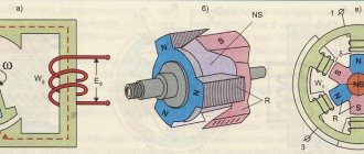
Principle of operation
TEG is based on a thermoelectric phenomenon described in the early 20s of the 19th century by the German physicist Thomas Johann Seebeck. He discovered the appearance of an emf in a closed circuit consisting of a conductor and antimony, provided that a temperature difference was created in the places where these materials were in contact. An image of the device with which this effect was recorded is presented below.
Thermocouple from the Seebeck experiment
Designations:
- 1 – copper conductor.
- 2 – antimony conductor.
- 3 – compass needle.
- A and B are the contact points of two conductors.
When one of the contacts was heated, the needle deviated, indicating the presence of a magnetic field caused by EMF. When the other contact was heated, the direction of the EMF changed to the opposite. Accordingly, when a circuit breaks, it is possible to record the potential difference at its ends.
12 years later, after Seebeck published the results of his experiments, the French physicist Jean Peltier discovered the opposite effect. If current is passed through the thermocouple circuit, a temperature difference occurs at the points of contact of these substances. We will not provide a description of Peltier’s experiment, as well as data on modern elements of the same name; this information can be found on our website.
In fact, both of these effects are the reverse sides of one thermoelectric phenomenon, which allows one to directly obtain electricity from thermal energy. But, before the discovery of semiconductors, the thermoelectric effect did not find practical application due to the unacceptably low efficiency. It was possible to raise it to 5% only in the middle of the last century. Unfortunately, even for modern semiconductor elements, this figure remains at the level of 8%-12%, which does not allow us to consider generators of this type as serious competitors of thermal power plants.
Modern Peltier element with dimensions
Efficiency of TEG
Evaluated by efficiency. The power of a thermoelectric generator depends on two critical factors:
- The amount of heat flow that can successfully move through the module (heat flow).
- Temperature deltas (DT) are the temperature differences between the hot and cold sides of the generator. The larger the delta, the more efficiently it works, so the design must provide conditions for both maximum cold supply and maximum heat removal from the walls of the generator.
The term "efficiency of thermoelectric generators" is similar to the term applied to all other types of heat engines. So far it is very low and amounts to no more than 17% of the Carnot efficiency. The efficiency of a TEG generator is limited by the Carnot efficiency and in practice reaches only a few percent (2-6%) even at high temperatures. This is due to the low thermal conductivity in semiconductor materials, which is not conducive to efficient power generation. Thus, materials with low thermal conductivity, but at the same time with the highest possible electrical conductivity, are needed.
Semiconductors cope with this task better than metals, but are still very far from those indicators that would bring a thermoelectric generator to the level of industrial production (with at least 15% use of high-temperature heat). Further increase in the efficiency of TEG depends on the properties of thermoelectric materials (thermoelectrics), the search for which today is occupied by the entire scientific potential of the planet.
The development of new thermoelectrics is relatively complex and expensive, but if successful, it will cause a technological revolution in generation systems.
Prospects
Currently, experiments are ongoing to select optimal thermocouples, which will increase efficiency. The problem is that it is difficult to provide a theoretical basis for these studies, so you have to rely only on the results of experiments. Considering that the effect is influenced by the percentage and composition of the alloys of the material for thermocouples, talking about the immediate prospects is a thankless task.
There is a high probability that in the near future, in order to increase the quality factor of thermoelements, developers will move to another level of manufacturing alloys for thermocouples, using nanotechnology, quantization pits, etc.
It is quite possible that a completely different principle will be developed using non-traditional materials. An example is experiments conducted at the University of California, where an artificially synthesized molecule was used to replace a thermocouple, which connected two gold microconductors.
Molecule instead of thermocouple
The first experiments showed the possibility of implementing the idea; time will tell how promising it is.
Future market
Although TEG technology has been used in military and aerospace applications for decades, new TEC materials and systems are being developed to generate energy using waste heat at low or high temperatures and this could provide significant opportunities in the near future. These systems can also be scaled to any size and have lower operating and maintenance costs.
Overall, investments in TEG technology are growing rapidly. The global market for thermoelectric generators is estimated at US$320 million in 2015. According to a recent study, TEG is expected to reach $720 million in 2022 with a growth rate of 14.5%. Today, North America holds 66% market share and will remain the largest market in the near future.[31] However, growth in Asia-Pacific and Europe is projected to be relatively higher. The study found that the Asia-Pacific market will grow at a compound annual growth rate (CAGR) of 18.3% between 2015 and 2020 due to high demand for thermoelectric generators from the automotive industry to improve overall fuel efficiency. as industrialization increases in the region.[32]
Small-scale thermoelectric generators are also in the early stages of wearable technology research to reduce or replace charging and boost charging times. Recent research has focused on the novel development of a flexible inorganic thermoelectric, silver selenide, on a nylon substrate. Thermoelectrics present a special synergy with wearable devices, harvesting energy directly from the human body, creating a self-powered device. One project used n-type silver selenide on a nylon membrane. Silver selenide is a narrow bandgap semiconductor with high electrical conductivity and low thermal conductivity, making it ideal for thermoelectric applications.[33]
The low-power TEG or "subwatt" market (i.e., generating peak power up to 1 W) is a growing part of the TEG market using emerging technologies. Main applications are sensors, low power applications, etc. Internet of Things Applications. A specialist market research company reported that 100,000 units were shipped in 2014, with 9 million units expected annually by 2020.[34]
Scope of application and types of thermoelectric generators
Due to the low efficiency of TEG, there are two application options:
- In places where other sources of electricity are not available.
- In processes where there is excess heat.
Here are a few examples of such devices.
Energy furnaces
Data, devices that combine the following functions:
- Cooking surface.
- Heater.
- Source of electricity.
This is a great example that combines both applications.
Indigirka - three in one
The energy furnace shown in the figure has the following parameters:
- Weight – a little more than 50 kilograms (excluding fuel).
- Dimensions: 65x43x54 cm (with disassembled chimney).
- The optimal loading of organic fuel is 30 liters. The use of deciduous wood, peat, and drilled (not hard) coal is allowed.
- The average thermal power of the device is about 4.5 kW.
- Electrical load power from 45-50 W.
- Stabilized constant output voltage – 12 V.
As you can see, these parameters are quite acceptable for conditions where there is no electricity, heating or gas. As for the small electrical power, it is quite enough to charge mobile devices or power other gadgets through an adapter from a car cigarette lighter.
Radioisotope TEGs
The thermal energy released during the decomposition of unstable elements can act as a heat source for TEG. Such sources are called radioisotope. Their main advantage is that constant fuel loading is not required. The disadvantage is the need to install protection against ionizing radiation, the impossibility of refilling fuel and the need for disposal.
The service life of such sources directly depends on the half-life of the substance used as fuel. The latter is subject to the following series of requirements:
- A high volumetric activity coefficient, that is, a small amount of a substance must provide the required level of energy release.
- Maintains the required power level for a long time. This parameter is answered, as noted above, by the half-life, for example, for strontium-90 it is 29 years, therefore, after this time the source will lose half of its power.
- Ionizing radiation must be convenient for disposal, that is, it must be dominated by α-particles.
- Required level of security. That is, ionizing radiation should not harm the environment (in the case of operation on earth) and equipment powered by such a source.
The isotopes curium-244, plutonium-238 and the above-mentioned strontium-90 meet these criteria.
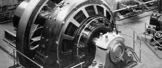
Scope of application of RTG
Despite the serious requirements for such sources, their scope is quite diverse; they are used both in space and on earth. The photo below shows the RTG that operated on the Cassini spacecraft. The isotope of plutonium-238 was used as fuel. The half-life of this element is just over 87 years. At the end of the 20-year mission, the source generated 650 W of electricity.
The radioisotope “heart” of Cassini
Cassini was given as an example, and in terms of mass production, it can be stated that almost all spacecraft use RTGs to power their equipment. Unfortunately, the characteristics of radioisotope energy sources of spacecraft, as a rule, are not published.
On earth the situation is approximately the same. RTG technology is known, but its details are classified information. It is reliably known that such installations are used as a power source for navigation equipment in areas where, for technical reasons, it is impossible to obtain electricity in any other way. That is, we are talking about hard-to-reach regions.
Unfortunately, such sources are not the most suitable alternative to thermal power plants from an environmental point of view.
RTG raised from a 14-meter depth near Sakhalin
Timeline of invention development
Following the first swallows, the Seebeck effect was applied further. A patent for the use of thermoelectric generators instead of conventional ones was taken out in 1843 by Moses Poole.
Perheliometer for measuring solar activity
The perheliometer is designed to measure the intensity of solar radiation by the degree of heating of the thermocouple. Invented by Claude Poulier between 1837 and 1838, the device allowed the scientist to calculate with a high degree of accuracy the solar constant of 1228 W/sq. m. Initially, the perheliometer was not intended to be used as a thermoelectric generator. Individual developments in the design served as a support for further progress in the industry.
Let us present data on the invention, taken from the scientific report of Dr. Stone, read on November 18, 1875. “Alloys exhibit properties more powerful in a combination of metals than each of the simple materials separately. Composed of one part zinc and two parts antimony, the sample gave a potential difference of 22.7. Potentials of the components taken separately:
- Antimony – 7 – 10.
- Zinc – 0.2.
The only exception was the alloy of bismuth and tin. With his 12 to 1 lineup, the potential drops from 35.8 to 13.67. I was lucky enough to start my research with a pair of nickel silver (rich in nickel) and iron. The observed EMF was not large. Then I tried Marcus' alloy, consisting of 12 parts antimony, 5 zinc and 1 bismuth. The result was fragile and with a pronounced crystalline structure.
To smooth out these shortcomings, arsenic was added. As a result, it was found that an alloy of antimony, arsenic and zinc with a small admixture of tin exhibits much greater ductility with similar thermoelectric properties as those observed in the Marcus alloy. The second part of the pair is nickel silver.”
Thermopile
Marcus's thermopile was one-twentieth the size of Daniel's, providing 55 mV of DC voltage. The negative “plating” was an alloy of copper, zinc and nickel in a ratio of 10:6:6, similar in appearance to nickel silver; positive – a compound of antimony, zinc and bismuth in a ratio of 12:5:1. According to “Electricity in The Service of Man”, 3rd edition, 1896, in May 1864 Marcus received a prize from the Vienna Scientific Society for a thermoelectric generator. The thermocouples formed by the hut were connected in the upper part by a heated metal strip. The lower parts were cooled with water. Unfortunately, the alloys quickly oxidized in air with a tremendous increase in the ohmic resistance of the contacts.
Becquerel's contribution
It is not known for certain when Edmond Becquerel’s thermoelectric generator was born, but historians date the discovery to the period 1867-1868. In its design, the transition is formed by copper sulfide and nickel silver. In the image: cold water was pumped into the near tank, and hot gas into the far one. The thermoelectric generator voltage was taken from the spiral terminals.
Clamond thermogenerators
Regarding thermoelectric generators, Dr. Stone said: “The use of iron gives a good effect, which is offset by the rapid rusting of the product.”
- The thermoelectric generator (probably dated 1874) by Clamond and Moore is constructed from zinc antimonide and pure iron specifically for the purpose of electrolysis. The heated device made it possible to obtain about an ounce of copper in an hour by consuming 6 cubic feet of gas. Used for cladding metal products. The gas regulator of the thermoelectric generator changed the amount of electric current received. In the presented top view, sectors made of zinc antimonide are visible, triangular sheet blades are made of iron.
- In 1789, Clamond's thermoelectric generator was greatly improved. With an internal resistance of 15.5 ohms, it produced a voltage of 109 V at a current of 1.75 A, consuming 22 pounds of coal per hour. By switching connections, the voltage decreased to 54 V. The current of the thermoelectric generator increased to 3.5 A. The structure, heated by a coal furnace, 2.5 meters high and within a meter in diameter, reminiscent of a cooler for modern processors, contained numerous iron wings on the outside. Gases passed inside, heating the zinc antimonide. According to some reports, the generator's 20 thermocouples produced 1 V of voltage.
- Noe's thermoelectric generator (probably 1874) is more reminiscent of a modern thermal power plant turbine in shape. The central part of the thermocouples is heated by the burner, and the periphery is cooled due to radiation and convection. This is a relatively small version of a Clamond generator with an internal resistance of 0.2 Ohm, designed for a voltage of 2 V and consisting of 128 thermocouples. The efficiency of the thermoelectric generator was greatly reduced by nickel silver intermediate contacts that dissipated heat. Modern thermoelectric generators use a pn junction without intermediate materials between the semiconductors.
- Hawk's portable thermoelectric generator (probably 1874) was rated at 110 mV (one tenth of a Daniel cell) and included 30 thermocouples, with the halves connected by 1.2 inch long platinum wire. The burner was very similar to a Bunsen burner, and the cold end was immersed in water. The design strongly resembles the inventions of Noe and, to a lesser extent, Clamond. The key difference lies in the industrial production of products for a mass range of consumers. Generators were sold in twos and threes, placed on a single base.
- The carbon thermoelectric generator was invented by Harry Barringer and copyrighted by patent US434428 from 1890.
Gülcher battery
The last design invented in the 19th century. Historians date it back to 1898. 50 thermocouples gave a voltage of 1.5 V at a current of 3 A and an internal resistance of 0.5 Ohm. For these purposes, 5 cubic feet of gas are spent every hour. According to the researchers, a good device would produce three times more at the same flow rate.
A full-scale experiment showed an average service life of 200 hours, although one sample worked for 500; finally, a sample was found that lasted two whole years. In 1903, a certain magazine published information about general tests of the Gulcher battery. During operation, the lit burner heated the thermocouples until the voltage reached 3.5 V. Then the device was turned off and the characteristics were looked at after the gas supply was stopped. When the voltage dropped to 1.5 V, the current abruptly stopped. Conclusion:
– Thermal stress is stable, which is due to significant thermal inertia. Temperature changes occur slowly, the voltage gradually drops as it cools.
However, a similar thing was also noticed by Poggendorff, who advised Georg Ohm to use a thermocouple instead of a voltaic column. The Gülcher battery proved popular at the beginning of the 20th century. For example, Lehigh University reports that for a new metallurgical laboratory in 1905, it purchased three Scott thermopiles and one Gulcher thermopile.
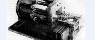
The design resembles a heating radiator that is outdated today. Similar ones are found in public buildings built and equipped in the USSR. This is a portable device: there is a T-shaped handle on each side for transportation.
Portable generator
The Shudre portable thermoelectric generator resembles a truck oil filter in appearance. To obtain heat, you need to light a gas burner. Very little information about the device has been preserved. In publications of 1898, information was found about joint tests of the product with those mentioned above in the text:
“Professor Kohlrauch noticed in the 70s that the voltage of a thermoelectric generator depends on the number of pairs connected in series. This is confirmed by experiments on the designs of Clamond, Noe and Choudre, manufactured and sold over the past 20 years. They produce 2, 4, 6 and 8 volts, having, respectively, 36, 72, 108 and 144 pairs. It can be seen that the voltage is strictly proportional to the total number. Shudre constructed a specimen consisting of 720 elements. As would be expected, the resulting voltage was 40 V, capable of keeping the discharge lamp burning.”
The note stated that novice electricians have the right to take the sample shown in the photo as an example of a commercially successful product. The Shudre thermoelectric generator is manufactured in 6 standard sizes, for currents of 1.3 - 2.5 A at voltages of 3 - 8.5 V, depending on the dimensions and number of elements.
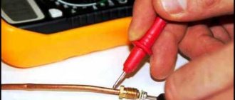
How to make a thermoelectric generator with your own hands?
In conclusion, we’ll tell you how to make a TAG that you can use on a camping trip, hunting or fishing. Naturally, the power of such devices will be inferior to radioisotope energy generators, but due to the inaccessibility of plutonium and its unpleasant property of causing harm to the human body, one will have to be content with little.
We will need a thermoelectric element, for example, TEC1 12710. It is advisable to use several elements connected in parallel to increase power. Unfortunately, there is a very serious nuance here; you will need to select elements with similar parameters, which is practically impossible for Chinese products, and using a branded one is expensive; it’s easier to buy a ready-made generator. If you use one Pelte module, then its power is barely enough to charge a phone or other gadget. We will also need a metal case, for example, a used PC power supply and a heatsink from the processor.
Assembly highlights:
We apply thermal paste to the case in the place where the thermoelectric element will be attached, lean it against it and fix it with a radiator. As a result, we get a design like the one in the bottom picture.
Tourist TEG
It is best to use “dry alcohol” as fuel.
Now we need to connect a voltage stabilizer to our source (the diagram can be found on our website or in other thematic sources).
The design is ready, you can start checking.
Content
- 1. History
- 2 Construction 2.1 Thermoelectric materials
- 2.2 Thermoelectric advantages
- 2.3 Thermoelectric module
- 2.4 Thermoelectric systems
- 3.1 Common materials
external reference
- Callendar, Hugh Longbourn (1911). "Thermoelectricity". Encyclopedia Britannica
.
26
(11th ed.). pp. 814–821. - J. Jeffrey Snyder's Small Thermoelectric Generators
- Kanellos, M. (November 24, 2008). Harnessing America's secret source of power. Retrieved from Greentech Media, October 30, 2009. Website: https://www.greentechmedia.com/articles/read/tapping-americas-secret-power-source-5259/
- LT Journal October 2010: Ultra Low Voltage Harvester Uses Thermoelectric Generator for Battery-Free Wireless Sensors
- DIY: How to build a thermoelectric power generator from a cheap Peltier block
- Gentherm Inc.
- This device uses the cold night sky to generate electricity in the dark.