This value of electric current is used to power most household appliances in the house. Often, they receive their charge from battery-powered devices.
But if they break, then a problem arises: how to get 12 Volts AC?
This is what we will try to analyze further, recalling the most common options.
Get a voltage of 12 Volts from 220
This is a fairly common change that can be made in several ways:
- Reduce tension without using a distributor.
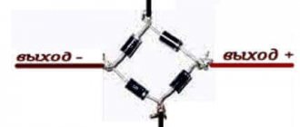
- Use a 50 Hz distributor.
- Connect a pulse transformer that can be combined with a straight-line rectifier.
A capacitor improves the situation
As you can see in the diagram, adding a polyester capacitor in series with the power line improves efficiency. In this configuration, the efficiency is already up to 20%.
Since the maximum voltage across the capacitor is greater than 320V, it is necessary to select a component that can operate at a voltage of at least 600V, as shown in the figure.
In this configuration, the R1 only dissipates 0.5W, but it is always better to use it with a power rating of at least 2W. Capacitor C2 acts as a resistor and has some capacitance at 50 Hz. More specifically, the capacitance of the capacitor at frequency f is determined by the following formula:
From the above formula, capacitor C2 has a reactance of 6772 ohms at 50 Hz, but, unlike a resistor, it does not generate heat. The output voltage of the circuit is also 12 V minus the voltage drop across diode D1.
HOW TO GET A REDUCTION WITHOUT USING A DISTRIBUTOR
This is only possible in three ways:
- Get a reduction using a damping element. Quite a popular method, used to recharge low-power devices. The disadvantages include a low power factor. However, it is often used in inexpensive devices.
- Limit the flow with a resistor. The option is not the best, but it is still used and is suitable for charging diodes. The main disadvantage is the large heat generation on the resistor.
- Use an automatic distribution transformer or a similarly wound coil.
SILENCER HEAT RECEIVER
Before we look at this topic, let's talk about the rules that need to be followed:
- The power supply unit is designed to work with only one device.
- Each of the external elements must be covered with insulation. Do not touch the electronic circuitry of the unit unless there is a load connected to it or a stabilizer is not connected to it to reduce the DC current.
This sequence cannot cause death, but the unpleasant effects of electricity are guaranteed.
The value of the reducing cooler is determined by the equation:
C (microfarad) = 3200 x I (load) / root of (U input sq. - U output sq.) or C (uF) = 3200 x I (load) / root of U input
It is useless to obtain in other ways, due to the reduction in intensity from 220 to 12 V by a resistor, a lot of heat is generated, and it does not make sense to wind the inductor to obtain the required Volts, because it is very expensive and difficult to implement.
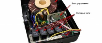
Self-production of the device
The design of the transformer seems complicated only at first glance. Many home craftsmen can quite easily assemble a step-down device with their own hands.
In order to get a working device, you need to follow the recommendations of specialists and a certain procedure:
In the absence of special equipment, winding coils can be greatly simplified with a simple device. Its design consists of two wooden posts mounted on a board and a metal axle threaded through holes in the posts. For ease of rotation, one end is bent in the form of a regular handle.
Expert opinion
It-Technology, Electrical power and electronics specialist
Ask questions to the “Specialist for modernization of energy generation systems”
What can 12 or 24 volts be used for in everyday life? Next, lamps are connected in parallel to it, and its role is to reduce the voltage from standard 220 Volts to 12 Volts required to power halogen spotlights. Ask, I'm in touch!
SUPPLY BOX ON MAINS DISTRIBUTOR
Standard and widely used sequence, used for music amplifiers and radio tape recorders. But only if you connect a good filter cooler that can make the necessary pulsation.
Plus, connect a 12 Volt stabilizing element. In its absence, the intensity will change due to current surges in the network: U output=U input* by coefficient. Transform.
Remember, the output voltage can be obtained 2-3 values higher than the output voltage of the BP-12 V, but not higher than thirty, it is determined by the capabilities of the stabilizer and its strength balances between the incoming and outgoing force.
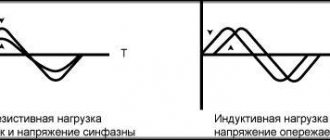
The distributor's ability to receive 12-15 volts of varying flow. The forward tension will be slightly higher, about 1.41 times. It will approach a sine wave at the input voltage.
Recommendations for power supply design
When the circuit is disconnected, capacitor C2 can remain charged for a long time. It is recommended to connect a high resistance resistor in parallel with this element, as shown in the figure. This resistor, for example with a resistance of 470 kOhm, does not affect the normal operation of the circuit. Under standard conditions, it dissipates about 100 mW of heat. The complete discharge of capacitor C2 occurs in approximately 1 second, but after 0.4 seconds the voltage value on this element will become non-hazardous to humans.
It should be noted that R2 must be designed to operate at such a high voltage. Therefore, it is common to use two or more regular 1/4 W resistors in series (to increase the maximum breakdown voltage).
As for a series resistor with a current-limiting capacitor, the resistor cannot be completely replaced with a jumper, because when connecting the power supply to the network, you can catch the top of the sine wave and the reactance of the capacitor will be on the order of units of ohms rather than kiloohms. The resistor is a protection against such “luck”. In turn, a large resistor means large power losses and even lower efficiency.
Here is a relatively powerful power supply made for a current of 150 mA 24 V. In addition to current limiting elements and a discharge resistor (C 2.5 uF, R 51R and 1M), the board has a diode bridge, a 24 V zener diode and a 100 uF filter capacitor.
In general, the greatest advantages of a transformerless power supply can be seen when current requirements are up to 30 mA, then of course the weight, number of elements, ease of operation will make the choice of such a circuit a reasonable choice. But always remember about the lack of galvanic isolation from the 220 V network!
Power supply forum
OPTIONS TO GET A FLOW REDUCTION FROM 24 TO 12 VOLTS, OR A STABLE VOLTAGE
To obtain a stable flow from twenty-four to twelve values, it is recommended to use a linear or pulsating stabilizing element.
The need for this appears in order to get power from a bus or truck, its power is 24 Volts.
In addition, you will acquire an already stable intensity that tends to change. Even in motorcycle wiring it rises to 14.7 V.
Therefore, this sequence can be used to recharge diode strips and light points on a car.
It is allowed to connect a load from 1 to 1.5 A. In order to increase the flow, a pass-through receiver is added, but after that the incoming voltage may drop by 0.5 V.
You can also use LDO-stabilizing elements; they are linear, but have a slight reduction in force.
For example, pulsating: AMSR-7812Z, AMSR1-7812NZ. Their connection is similar to L7812. The same methods are used to reduce the flow intensity from the laptop's power supply.
It is best to use pulsed current-reducing voltage converters, for example the LM2596 IC. The electronic circuit shows the input and output (In, Out).
In stores there is an option with a stable output voltage, as well as with a controlled one.
Resistive transformerless power supply
The circuit diagram of a typical transformerless resistive power supply is shown in the figure.
Again, the output voltage Vout remains constant as long as the current Iout is less than or equal to the input current Iin, the only difference being that the inrush current limiting is now implemented only by resistor R1. The output voltage Vout can be calculated using the same formula as for a capacitive power supply, and the input current Iin using the following formula:
As in the previous case, components must be selected with a power value at least twice the theoretical value that can be calculated by Ohm's law (P = R x I^2 for R1 and P = V x I for diodes D1 and D2) . Electrolytic capacitor C2 should be selected as for capacitive design.
The advantage of a resistive power supply is that it is smaller in size and weight compared to a transformer circuit and is the cheapest power supply solution. But even in this case there is no galvanic isolation from the AC network, and in addition, the efficiency is lower than in a capacitive solution.
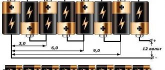
INCREASE FIVE VOLTS TO TWELVE
This can be done using lithium batteries with a current of 3.7-4.2 V.
If he talks about power blocks, if you have certain knowledge, you can intervene in the internal circuit.
Or make it much easier and achieve 12 V by connecting a boost converter. In the store you can purchase models with stable (12 V) or adjustable voltage (from 3.2 to 30 V) at an output of 3 A.
This converting element is sold on a ready-made electronic circuit, which has input and output marks.
An additional way is to take the MT 3608 LM 2977, the ability to raise the current to 24 V and transfers the output voltage to 2 A. In the picture below, the input and output locations are clearly visible.
Operating principle of a step-down transformer
- Electric current enters the primary coil, which creates a magnetic field.
- Near the coil conductors, all power lines are closed. Some of them may capture conductors belonging to another coil. As a result, an interconnection of both coils is formed through magnetic lines.
- The force of interaction directly depends on the distance between the windings. The farther they are from each other, the weaker the strength of the magnetic bonds.
- The alternating current passing through the first coil changes over time in accordance with certain laws. Consequently, the magnetic field created by it will also be variable.
- Magnetic flux with changed magnitude and direction enters another coil, thereby inducing an alternating electromotive force. An electric current appears at the output of the second coil. Its value is regulated by the ratio of the number of turns in the first and second coils. The result may be a step-down transformer or, conversely, a device that increases the current.
Useful tips Connection diagrams Principles of operation of devices Main concepts Meters from Energomer Precautions Incandescent lamps Video instructions for the master Testing with a multimeter