Alternative ways to generate electricity are gaining more attention as energy prices rise. So projects arise in which inventors are trying to get free electricity from thin air in sufficient quantities.
Moreover, this question is not just discussed on Internet forums among amateurs trying to create power plants with their own hands, but is also raised in all seriousness by scientists trying to propose their own schemes for generating electricity from thin air.
How to make free electricity at home?
Free electricity in the apartment must be powerful and constant, so to fully ensure consumption, a powerful installation will be required.
The first step is to determine the most suitable method. Thus, for sunny regions it is recommended to install solar panels. If solar energy is not enough then wind or geothermal power plants should be used. The latter method is especially suitable for regions located in relative proximity to volcanic zones. Having decided on the method of obtaining energy, you should also take care of the safety and security of electrical appliances. To do this, the home power plant must be connected to the network through an inverter and voltage stabilizer to ensure the supply of current without sudden surges. It is also worth considering that alternative sources are quite capricious in terms of weather conditions. In the absence of appropriate climatic conditions, electricity generation will stop or be insufficient. Therefore, you should also acquire powerful batteries for storage in case of lack of production.
Ready-made installations of alternative power plants are widely available on the market. True, their cost is quite high, but on average they all pay off in 2 to 5 years. You can save money by purchasing not a ready-made installation, but its components, and then independently design and connect the power plant.
How to remove static electricity in an apartment
Static electricity in an apartment can cause a lot of inconvenience to its owners, especially at the moment of its discharge. With a negligible current in the electrostatic discharge zone, the potential difference can reach tens of kilovolts. Moreover, the source of static electricity is not always electronic devices. Often the role of storage devices is played by quite ordinary and familiar things: a carpet on the floor, a favorite chair, or the person himself.
True, static electricity in a person is a consequence of his active interaction with these very household items, and the intensity of the manifestation of electrical unfriendliness in an apartment is associated with a number of factors: cleanliness, air humidity, finishing materials of furniture and premises.
Of great importance is the correct installation, grounding and timely maintenance of electrical household appliances, the service life of which will definitely be longer if their moving parts are not subjected to forced electrification. Wash or dust everything that rotates in your home. Be glad that in everyday conditions, achieving a breakdown voltage of the electrostatic field sufficient for open ignition is practically impossible.
DIY electricity from the ground
Zinc and copper electrode
The next method of generating electricity is based on using only land. Two metal rods are taken - one zinc, the other copper, and placed in the ground. It is better if it is soil in an isolated space.
Isolation is necessary in order to create an environment with high salinity, which is incompatible with life - nothing will grow in such soil. The rods will create a potential difference, and the soil will become an electrolyte.
In the simplest version, we get a voltage of 3 V. This, of course, is not enough for a home, but the system can be complicated, thereby increasing the power.
Neutral wire – load – soil
Voltage is supplied to residential premises through 2 conductors: phase and neutral. When creating a third, grounded conductor, a voltage of 10 to 20 V arises between it and the zero contact.
This voltage is enough to light a couple of light bulbs. Thus, to connect electricity consumers to “ground” electricity, it is enough to create a circuit: neutral wire - load - soil. Craftsmen can improve this primitive circuit and obtain a higher voltage current.
Many thanks to the sites for the excellent material: www.0el.ru,lidol.ruotlad.ru
DIY electricity from the ground
Nevertheless, many people do not give up trying to extract electricity from the earth in order to make their lives easier or change, and they should not be stopped, because the most important discoveries in the history of mankind were made by persistent people who were in love with their ideas.
Alternating current, which powers all electrical appliances in apartments, enters homes through two conductors: zero and phase. Due to grounding, a large amount of energy goes into the soil. Of course, no one wants to pay for something that they cannot fully use. Therefore, enterprising people have long understood how to extract energy from the earth using a neutral wire.
This method is based on the fact that the earth, due to its physical properties, is both an energy store and its conductor.
Underground cable laying diagram
To extract electricity, you need to create a simple circuit.
- At a sufficient distance, two metal stakes are dug into the ground, one of which is the cathode, and the second is the anode, as a result of which energy with a voltage of 1 to 3 V will appear. The current strength in this case will be negligible.
- To increase the voltage and current, you will have to drive a lot of pins into an area with a huge area, both in series and in parallel connected to each other. A series connection increases the voltage, and a parallel connection increases the current.
- When the voltage reaches 20-30 V, it is necessary to connect a simple transformer to the circuit to increase the output voltage and a battery to accumulate and stabilize electrical energy. The last stage is the transformation of direct thirty-volt current into alternating current, with a voltage of 220 V.
Zinc and copper electrode
This is the simplest, cheapest and most effective way to generate electrical energy at the moment; it is on this principle that the batteries we are used to are constructed.
The first step is to isolate a certain amount of soil in order to create the most acidic environment possible. Then connect the zinc and copper electrodes to this isolated ground. The output actually turns out to be electricity. This principle of obtaining energy largely depends on the quality of the soil - the more acidic it is, the better.
Zinc and copper battery
You can conduct an interesting experiment by placing two keys - copper and iron - in an orange. The result is a voltage of up to 1 V. The decisive factor is the area of the electrodes in contact with the acid and the acidity level of the orange itself.
This amount of energy is enough to charge a simple phone. To increase the power, you need to connect several more of the same circuits in parallel to this circuit. As a result, you will be able to charge a smartphone or laptop, but you will have to allocate a huge room for a power station made of oranges and electrodes.
This method of obtaining energy is good, but not reliable and not durable: as soon as the zinc and copper electrodes begin to oxidize, the voltage will begin to drop, and then the energy supply will stop. The situation can be corrected by cleaning off the oxide and adding acid.
Potential between roof and ground
A metal pin is installed in the ground, a wire is pulled from it to the roof, and the resulting electrical energy can be safely used.
True, only until the first thunderstorm, because in essence it is a real guide.
At best, wiring and electrical appliances will be damaged; at worst, the lives of the inhabitants of the house will be threatened.
What else?
Among the usual ones, you can also find quite unusual ways of generating electricity. Recently, scientists around the world have been intensively working on the development of alternative energy. The world is looking for opportunities for its wider use.
Below is a short overview of the best methods and ideas:
Thermal generator – converts thermal energy into electrical energy. Built into heating and cooking stoves.
Piezoelectric generator – works on kinetic energy. They are introducing dance floors, turnstiles, and exercise equipment.
Nanogenerator - uses the energy of vibrations of the human body during movement. The process is instantaneous. Scientists are working on combining the work of a nanogenerator and a solar battery.
Experimental installations that operate on ether - electromagnetic field. While the search is still underway, hypotheses are being tested, experiments are being conducted.
Scientists have calculated that the natural reserves used in modern energy may last for another 60 years. The best minds are working on developments in this area. In Denmark, the population relies on wind energy for 25%.
In Russia, projects are planned to use renewable sources in the energy system by 10%, and in Australia by 8%. In Switzerland, the majority voted for a complete transition to alternative energy. The world votes yes!
Grounding example
This method is suitable for owners of a private home. When a home is equipped with a correct grounding loop, some of the current enters the ground, especially when several powerful electrical appliances are operating simultaneously. The potential difference between the ground wire and phase zero can reach 15-20 V. This way you can charge your phone for free, the meter will not take it into account.
The method can be improved by installing a transformer, this will equalize the voltage. Connecting the battery at a time when the main consumers of electricity at home are turned off will make it possible to stock up on energy for future use. A completely working method, which is not suitable for apartments, since water pipes cannot be used, and connecting to ground and phase can end sadly.
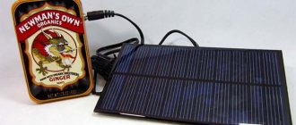
Free electricity from the sun
Solar batteries are very popular in Europe. You've probably heard about this method of generating electricity. And it really works, and is not an option on how to make money on glass.
Of course, in order to use such energy, you first need to spend a lot of money, because solar panels are not cheap, and in order to provide the entire house with such energy, you will need to buy a lot of them. You also need to take into account that if your house is in the forest, it will not be possible to convert solar energy into electricity. Problems can also arise during the cold season. However, solar stations have several significant advantages.
Advantages of solar power plants:
- Solar energy is eternal;
- It does not release harmful substances into the environment and does not contribute to the accumulation of radio waves;
- You will be able to calculate in advance how much energy you can get from a particular number of batteries;
- The price spent on batteries will be recouped over time due to the savings on electricity.
Solar electricity is an excellent alternative to centralized electricity. All your electrical needs can be covered with it.
Briefly about the main thing
Correctly selected curtains transform the interior, emphasize style and add coziness.
The method of attaching the decor also plays a role in this transformation. The type of fastener is determined by the chosen cornice, which, in turn, depends on the interior style. For each type of cornice, there are several types of fastening, which greatly simplifies the task of choosing. All types of fasteners have their own scope, advantages and disadvantages. When choosing fasteners, they take into account what fabric it is intended for, and also consider whether it fits into the style of the living room, bedroom or office.
Electricity from water at home
This pipe can convert the pressure of tap water into electricity, which can be used for home use.
To generate electricity, you need to install a device in the pipe, then open the valve. The water will then produce the desired electricity by moving small wheels inside the device.
The generated energy is accumulated in special lamps, which are installed after charging in their place for the intended use, and the brightness of their glow can be adjusted.
This method can be used by people all over the world where tap water is available. It's strange that no one thought of this before. Therefore, Choi’s invention reached the finals of an industrial design competition and is already being prepared for serial production. One English inventor, Ryan Yongwoo Choi, developed a method for generating electricity at home from tap water, and came up with a pipe that has a water wheel inside, and called it ES Pipe Waterwheel.
Definition of alternative heating
Alternative sources of heating a private home include types of heating systems that use natural energy sources. At the same time, the costs of installing such installations should be affordable and incomparable with the cost of the serviced home. Such schemes are used, as a rule, in country houses. For residents of apartment complexes, this issue does not arise, since each apartment is connected to centralized heating.
Interest in alternative heating sources is associated with a steady increase in prices for most common energy sources. This also applies to the cheapest option – main heat supply. Due to limited natural resources, this trend will continue in the future, forcing us to look for new sources of energy. In addition to the economic benefits, such methods of heating a house are good because the atmosphere is not polluted by solid and gaseous emissions produced by burning different types of fuel. This helps to improve the environmental situation.
Known methods for generating electricity
In the first case, electricity is generated from the ground using two rods made of dissimilar metals. This method has nothing to do with the Earth's electric or magnetic field. The rods are used as a galvanic couple placed in a saline solution. If the experiment is carried out in its pure form, then a potential difference, that is, an electric current, is formed at the ends of metal rods immersed in an electrolyte solution.
The amount of current received will vary depending on factors such as the size of the electrodes, the characteristics of the electrolyte, the depth of the deposit, etc.
Using the same scheme, you can get electricity from the ground. For this purpose, rods of copper and aluminum are taken, which will be used as a galvanic pair. They need to be buried in the ground by about 50 cm, located at a distance of 20-30 cm from each other. A large amount of saline solution is poured onto the soil area located between the rods, and after 5-10 minutes control measurements can be taken using an electronic voltmeter.
The voltmeter shows different values, the maximum result was 3 volts. An electrolyte solution is prepared from distilled water and table salt.
The second option for extracting current is also not related to the Earth's magnetic field. The idea is to extract the electricity flowing down the ground wire during times of maximum power consumption. The “zero” conductor also participates in this process.
Everyone knows that voltage is supplied to consumers via phase and neutral wires. If there is a third wire connected to the ground loop, voltage often arises between it and the neutral conductor, sometimes reaching up to 15 volts. This condition can be determined using a 12 volt incandescent lamp connected to both conductors. It is impossible to record it in any other way, since the metering devices do not react to this in any way and the current flowing from the “ground” to zero is not determined.
This method is unsuitable for apartments, since they usually do not have grounding that can perform its function. Similar experiments work well in private homes with a classic ground loop. The connection diagram is carried out from the neutral conductor to the load and then to the ground wire. In the process of extracting electricity from the ground with their own hands, some home electricians use transformers to smooth out current fluctuations and then connect the most optimal load.
It is strictly forbidden for a phase to be connected instead of the neutral conductor, in order to avoid deadly situations.
How to get
It’s easy to get static electricity at home:
- It is necessary to put on dry, clean wool socks (it is advisable to preheat them on a radiator) and walk on a nylon carpet without lifting your feet. You shouldn’t shuffle too much, as the discharge will happen faster than necessary. To receive a charge, you must touch a metal object or person;
The easiest way is to shuffle your feet in socks on the carpet.
Important! When checking, you should not touch the electronics, as the charge can damage the chips - statistically this is the cause of almost 40% of breakdowns
- You need to take a balloon (not made of foil) and inflate it. Then take a woolen object and rub the ball for 10 seconds. You can also place the ball on your head and rub it on your hair. To check, you need to bring the ball to an empty aluminum can lying on its side: if it starts to roll away, the charge has accumulated. To discharge, you need to rub the ball on the metal for a few seconds;
- To demonstrate and check the charge more clearly, you can make a special electroscope. You will need to take a glass made of foam polystyrene, make 2 holes in the bottom and thread a tube through them so that both ends are outside. You need to attach 4 small clay balls to the top edge with tape at an equal distance from each other, turn the glass over and place it upside down in the center of an aluminum baking sheet. Next, you need to take a piece of aluminum and roll a ball out of it, cut the thread (its length should be 2-3 times greater than the height from the edge of the straw to the baking sheet) and tie the ball to it. The second end must be tied to both ends of the tube, and the latter must be adjusted so that the aluminum ball hangs almost to the baking sheet, but does not touch it. If you bring a charged ball to the ball, the ball will be drawn towards it.
Another way is to rub the inflated balloon on your hair.
Prey from the air
Atmospheric electricity may well be used. Many are attracted by the opportunity to put natural elements at their service during a thunderstorm.
The atmosphere also contains waves from the planet's field. It turns out that electricity can be extracted from the air on your own, without using highly complex devices.
Some methods are as follows:
- lightning batteries use the property of electrical potential to accumulate;
- a wind generator converts wind power into electricity, operating for a long time;
- ionizer (Chizhevsky chandelier) is a popular household appliance;
- Stephen Mark's TPU (toroidal) electricity generator;
- Kapanadze generator is a fuel-free energy source.
Let's take a closer look at some of the devices.
Wind generators
A popular and well-known source of energy obtained from wind is a wind generator. Such devices have long been used in many countries.
A single installation provides limited power supply needs. Therefore, it is necessary to add generators if it is necessary to provide energy to a large enterprise. In Europe, there are entire fields with wind turbines that do not harm the environment at all.
It is worth noting:
A disadvantage may be the inability to calculate in advance the voltage and current values. Consequently, it is impossible to say how much electricity will accumulate, since the action of the wind is not always predictable.
Lightning batteries
A device that accumulates potential using atmospheric discharges is called a lightning battery.
The device circuit includes only a metal antenna and grounding, without complex converting and accumulating components.
Potential appears between the parts of the device, which then accumulates. The impact of natural disasters is not subject to precise preliminary calculation and this value is also unpredictable.
It is important to know: this property is quite dangerous when implementing the circuit with your own hands, since the created circuit attracts lightning with voltages of up to 2000 Volts
Toroidal generator S. Mark
The device, invented by S. Mark, is capable of generating electricity some time after it is turned on.
The TPU (toroidal) generator can power household appliances.
The design consists of three coils: internal, external and control.
It operates due to the emerging resonant frequencies and magnetic vortex, which promote the formation of current. Having drawn up the diagram correctly, you can make such a device yourself.
Generator Kapanadze
Inventor Kapanadze (Georgia) reproduced a free energy generator, the development of which was based on the mysterious N. Tesla transformer, which provides much greater output power than in the circuit current.
The Kapanadze generator is a fuel-free device that is an example of new technologies.
Starting is carried out from the battery, but further work continues autonomously. The body concentrates energy extracted from space and the dynamics of the ether. The technology is patented and not disclosed. This is practically a new theory of electricity and wave propagation, when energy is transferred from one particle of the medium to another.
Transformer
To wind the wire, thread its beginning into the bottom hole, leave a margin of 10-20 cm there and secure it with tape. After the winding is completed, its end of the same length is threaded into the upper hole and also secured.
Important! The turns of the winding must fit tightly to each other. The wire should not have kinks or loops.
The finished winding must be coated on top with electrical varnish or epoxy resin to prevent shifting of the turns.
For the secondary winding you need a more serious wire with a cross section of at least 10 mm2. This corresponds to a wire with a diameter of 3.6 mm. If it's thicker, that's even better.
Note! Since the system operates at a high frequency, due to the skin effect, the current propagates in the surface layer of the wire, so you can use a thin-walled copper tube instead. The skin effect is another justification for the large diameter of the secondary winding wire.
The diameter of the turns of the secondary winding should be twice as large as the primary, that is, 100 mm. The secondary can be wound on a 110 mm section of sewer pipe or on any other simple frame. A pipe or a suitable blank is needed only for the winding process. The rigid winding will not need a frame.
For the secondary winding, the number of turns is 5-6. There are several design options for the secondary winding:
The cone-shaped one is of the greatest interest because it expands the tuning range (has a wider frequency band). The lower first turn is made with a diameter of 100 mm, and the upper one reaches 150-200 mm.
Important! It is necessary to strictly maintain the distance between the turns, and the surface of the wire or tube must be made smooth (at best, polished).
DIY small Tesla coil
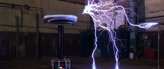
Looking at photos of homemade Tesla coils, you inevitably want exactly the same one for your home. After all, their work is such a beautiful sight that it is impossible to take your eyes off.
Expert opinion
It-Technology, Electrical power and electronics specialist
Ask questions to the “Specialist for modernization of energy generation systems”
Do-it-yourself Tesla coil: simple instructions and diagrams on how to make a transformer So, we don’t need to demonstrate aerobatics, so we will make the simplest coil that uses a transistor in its assembly. Ask, I'm in touch!
Where to get?
Traditional sources
And if we limit ourselves only to traditional technologies, then only two energy supply schemes can be distinguished:
Connection to power lines
- Centralized - the site is “powered” from a power line passing at a relatively short distance.
- Autonomous - the generator acts as a source.
Let's look at both options in more detail.
If we talk about the use of centralized energy supply, then the main advantage is the fairly high power provided. So, in this case, you can even organize heating of your dacha with electricity without going broke on fuel for the generator.
Connecting to wires on a pole
On the other hand, the process of connecting to power lines itself is associated with very tedious bureaucratic procedures. Even if the wires are laid relatively close, problems may arise at the coordination stage.
Note! Unauthorized connection to power lines is an offense, and if such a fact is discovered, you will have to pay a considerable fine. It is also worth remembering that such work should only be carried out by professionals with the appropriate level of clearance.
Renting a diesel generator for a summer residence or purchasing such a device can provide you with energy regardless of the location of the site. Yes, this technology is more expensive from a financial point of view, but this way you can be sure that the light in the house and area will not go out even during bad weather (wire breaks, especially in remote areas, are not uncommon).
Even a compact device can provide illumination for an entire house
Another option for autonomous power supply is the installation of a gas generator. Of course, the price of the device will be higher than that of a diesel unit, and only specialists can service it, but the cost per kilowatt of energy will be significantly lower.
As a result, the optimal instruction will be the following: if possible, connect to the power line and use its power, but just in case, install a generator in the house or barn with a small supply of fuel. If there is no possibility of connection, we simply buy a more productive generator, and design the electrical network of the site, taking into account the limitations on the installation’s performance.
Alternative sources
However, modern technologies make it possible to get electricity for free for your dacha. By “freebie” in this case there is complete or almost complete independence from energy prices. Of course, the alternative equipment itself needs to be purchased, and for quite a lot of money, but over time (from two to five years) it pays off, and then it works “plus”.
Photo of a wind generator impeller on the roof of a house
Several of the most effective technologies can be identified, and we have summarized their features in a table:
Reply to reader
Thank you, Alexander, for a very interesting question. This topic, believe me, worries not only you, but also a large number of inhabitants of our planet, including the author of this material, and there are several reasons for this.
- Firstly, this is a constant increase in energy prices, which greatly pushes up inflation for other goods, which is why we are forced to spin like squirrels in a wheel, constantly increasing production, plus modern banking systems, but let’s not talk about that.
- Secondly, many are haunted by the mysterious biography of the famous Serbian inventor Nikola Tesla, who, according to rumors, was able to build a full-fledged power plant that could provide an entire city with electrical energy taken from the ether, but the technology was blocked by the industrialists who reigned in America at that time .
- Thirdly, there are working schemes, which we will discuss today, and, as you know, everything that works can be improved.
On the Internet you can find a huge number of videos in which home craftsmen demonstrate their installations, which use the Earth’s magnetic and electric fields as an energy source. Some people even manage to sell such units, but we have never seen such devices in action, which, however, does not deny their real existence.
There are rumors that a certain Swiss company, whose name the author has successfully forgotten, officially sells compact devices for fabulous money, with the condition of servicing only by its specialists, compact installations capable of providing electricity to a full-fledged house with all the appliances in it.
However, it is worth understanding that most of these photos and video materials are fakes for the purpose of obtaining profit or fame, and excuses like, they say, we cannot post device diagrams, since the inventors are immediately “pressed” by the special services, can be considered only excuses. If you want, you can put anything on the Internet, and it will be impossible to completely clean it out, although we don’t want to completely deny the conspiracy theory. You never know...
But all this is poetry, let's talk about what we can build with our own hands, and whether such energy can be useful in everyday life.
What's true and what's a myth
Trying to light a light bulb
So, is it possible to get electricity by using the Earth's electric magnetic field?
Theoretically yes! The earth is, in fact, one huge capacitor with a spherical shape.
- A negative charge accumulates on the inner surface of the planet, while a positive charge accumulates on the outer surface.
- The insulator between them is the atmosphere through which current constantly flows, and the potential difference is maintained;
- Lost charges are restored due to the magnetic field, which is, in fact, a generator.
How to extract electricity from this simple circuit? The device must consist of the following elements:
- Tesla coil (emitter) is a high-voltage generator that allows electrons to leave the conductor;
- Conductor;
- A grounding circuit connected to a conductor.
Further instructions are simple in theory! Ideally, all we have to do is connect to the generator pole and take care of good grounding, but...
- The highest point of the installation, where the emitter is located, must be located at such a height that the potential of the Earth's electric field, or rather its difference, lifts electrons up the conductor.
- The emitter, in the form of ions, will release them into the atmosphere and this will happen until the level of potentials is equal.
- Current consumers can be connected to such a circuit, and their number will depend on the power of the Tesla coil.
- Yes, we almost forgot! It is necessary to take into account the height of all grounded conductors in the area (trees, metal poles, high-rise buildings, etc.) and make the installation higher than all of them, which makes the idea almost impossible to implement.
Electricity circuits from thin air
There are simple schemes for creating such devices; now this is easier to do, since there are many more networks and power lines, they contribute to the ionization of airspace.
There is nothing particularly complicated in the construction of such devices; the ground for it can be the ground, and the antenna will be a metal plate placed above the ground. The device will be able to accumulate the electrical potential available in the air, and in the future it can be used.
At the same time, you need to understand that even creating such a simple device yourself is fraught with certain risks; its operation creates the principle of lightning, which can pose quite a serious danger.
Another point is that it will be quite difficult to create a powerful device for generating electricity from the air; more serious circuits are used, which makes it very difficult for non-specialists to create such devices.
As for the simple device, it also has many advantages; it is simple in design, which makes it easy to create it at home. All materials for it are quite accessible.
- The disadvantages are the danger of this circuit, since it is difficult to calculate the approximate number of amperes and the strength of the current pulse.
- An open ground loop is formed, so lightning discharges up to 2000 volts can occur, which is very unsafe. It will be safer to obtain energy from the wind or through a solar panel.
As for Mark’s device, its principle is that a resonance of currents and magnetic vortices is created in the ring, and current shocks appear in the metal taps.
For such a generator you need a base, it can be a ring-shaped piece of plywood, polyurethane or a piece of rubber, 2 collector coils, and a control coil.
The outer diameter of the ring should be 23, and the inner diameter 18 cm. The coil is wound inside the collector, the winding must be made of three turns, it is made with stranded copper wire.
To power the light bulb, one turn should be enough, if that doesn’t work, you need another turn, you will need 4 control coils, place each at a right angle so that there is no interference with the magnetic field, the winding itself is made flat, with a gap between the turns of 1.5 cm.
To wind the control coils you need a single-core wire, at least 21 turns are made. The last coil requires an insulated wire; it is wound over the entire area.
Now all that remains is to connect the leads. A 10 microfarad capacitor must also be installed between ground and return ground. To power the circuit, multivibrators and transistors are needed; they are selected experimentally, since different characteristics are required for different designs.
You can try to create a more complex device. There are more complex diagrams on the Internet, as well as video instructions. If you visit the construction forum, you can find a lot of interesting things on this topic.
How to remove static electricity from a person
The simplest means of protection against it is to ground the equipment. In production conditions, screens and other devices are used for this purpose. Special solvents and additives are used in liquid substances. Antistatic solutions are actively used. These are substances with low molecular weight. The molecules in the antistatic agent move easily and react with moisture in the air. Due to this characteristic, static is removed from a person.
If the operator's shoes have non-conductive soles, he must always touch the ground. Then the flow of static current into the ground cannot be stopped, but the person will receive a strong or weak shock. We feel the effect of static current after walking on carpets and rugs. Drivers getting out of the car receive electric shocks. It’s easy to get rid of this problem: just touch the door with your hand while sitting still. The charge will flow into the ground.
Ionization helps a lot. This is done using an antistatic strip. It has many needles made of special alloys. Under the influence of a current of 4-7 kV, the air around is decomposed into ions. Air knives are also used. They are an antistatic strip through which air is blown and cleans the surface. Static charges are actively formed when liquids with dielectric properties are splashed. Therefore, to reduce the effect of electrons, a falling jet should not be allowed.
It is advisable to use antistatic linoleum on the floor and clean it more often using household chemicals. At enterprises involved in the processing of fabrics or paper, the problem of getting rid of static is solved by wetting the materials. Increasing humidity prevents harmful electricity from accumulating.
To remove static, you must:
- humidify the air in the room;
- treat carpets and rugs with antistatic agents;
- wipe the seats in the car and in the rooms with antistatic wipes;
- moisturize your skin more often;
- refuse synthetic clothing;
- wear shoes with leather soles;
- prevent the appearance of static on laundry after washing.
Indoor flowers, a boiling kettle, and special devices moisturize the atmosphere well. Antistatic compounds are sold in household chemical stores. They are sprayed over the carpet surface. You can make an antistatic agent yourself. To do this, take fabric softener (1 cap) and pour it into a bottle. The container is then filled with clean water, which is sprayed over the surface of the carpet. Wipes moistened with an antistatic agent neutralize charges on seat upholstery.
Moisturize the skin with lotion after a shower. Hands are wiped several times a day. You should change your clothes to natural ones. If it is charging, treat it with antistatic agents. It is recommended to wear shoes with leather soles or walk around the house barefoot. Before washing, it is advisable to sprinkle ¼ cup of baking soda on your clothes. It removes electrical discharges and softens the fabric. When rinsing clothes, you can add vinegar (¼ cup) to the machine. It is better to dry clothes in the fresh air.
All of the above measures help neutralize static problems.
Experiences of famous scientists
You can turn to the works of already famous scientists who in the past tried to obtain electricity literally from thin air. One of these people is the famous scientist Nikola Tesla. He was the first person to think that electricity could be obtained, roughly speaking, from nothing.
Of course, in Tesla's time it was not possible to record all of his experiments on video, so at the moment experts have to recreate his devices and the results of his research according to his notes and the old testimonies of his contemporaries. And, thanks to many experiments and research of modern scientists, it is possible to build a device that will allow generating electricity.
Tesla determined that there was an electrical potential between the base and the raised metal plate, representing static electricity, and he also determined that it could be stored.
Subsequently, Nikola Tesla was able to construct a device that could accumulate a small amount of electricity, using only the potential contained in the air. By the way, Tesla himself assumed that the presence of electricity in its composition, the air owes to the sun's rays, which, when penetrating space, literally divides its particles.
If we look at the inventions of modern scientists, we can give an example of the device of Stephen Mark, who created a toroidal generator that allows you to store much more electricity, in contrast to the simplest inventions of this kind. Its advantage is that this invention is capable of providing electricity not only to weak lighting devices, but also to quite serious household appliances. This generator is capable of operating without recharge for quite a long time.
Principle of operation
The coils you created have an oscillating circuit. If voltage is applied to the first coil, it will create its own magnetic field. With its help, energy is transferred from one coil to another.
The secondary coil creates, together with the capacitance, the same circuit that is capable of accumulating the energy transferred by the primary. Everything works according to a simple scheme - the more energy the first coil is capable of transmitting, and the second one is able to accumulate, the greater the voltage will be. And the result will be more spectacular.
To make a Tesla invention yourself, you need to do mathematical calculations, so you need to have experience. Or find an engineer who can help you derive the formulas correctly.
Expert opinion
It-Technology, Electrical power and electronics specialist
Ask questions to the “Specialist for modernization of energy generation systems”
Operating principle of the Tesla generator However, due to the pulsed nature of the output voltage, the BTG on a transformer cannot be used to power DC motors. Ask, I'm in touch!
A question of efficiency
Obtaining electricity from the earth is shrouded in myths - materials are regularly posted on the Internet on the topic of obtaining free electricity by using the inexhaustible potential of the planet’s electromagnetic field. However, numerous videos of homemade installations extracting current from the ground and causing multi-watt light bulbs to shine or electric motors to spin are fraudulent. If generating electricity from the ground were so efficient, nuclear and hydropower would have long since become a thing of the past.
However, it is quite possible to extract free electricity from the earth’s shell and you can do it with your own hands. True, the resulting current is only enough for LED backlighting or to slowly recharge a mobile device.
Voltage from the Earth's magnetic field - is it possible!?
To obtain current from the natural environment on a constant basis (that is, excluding lightning discharges), we need a conductor and a potential difference. The easiest way to find the potential difference is in the ground, which combines all three media - solid, liquid and gaseous. The structure of the soil is solid particles, between which there are water molecules and air bubbles.
It is important to know that the elementary unit of soil is a clay-humus complex (micelle), which has a certain potential difference. The outer shell of the micelle accumulates a negative charge, and a positive charge is formed inside it.
Due to the fact that the electronegative shell of the micelle attracts ions with a positive charge from the environment, electrochemical and electrical processes continuously occur in the soil. This makes the soil stand out from the water and air environment and makes it possible to create a device for generating electricity with your own hands.
Methods of protection against static in production
A set of protective measures is being developed and applied against the harmful and dangerous manifestations of accumulated static electric current in production conditions. They are based on the following methods:
- increasing the conductive properties of materials and the surrounding working environment, which leads to the dispersion of periodically appearing static electric charges in space;
- reduction in the speed of processing and movement of materials, which significantly reduces the possibility of generating static electric charges;
- full-scale use of well-designed grounding, which helps eliminate the accumulation of dangerous potentials;
- increasing the resistance of the machines and mechanisms themselves to the action of statistical discharges;
- preventing the penetration of electric current into the work area.
All methods used to prevent static electrical discharges are divided into structural, technological, chemical, physical and mechanical. The last three are aimed mainly at reducing the activity of generating electric charges and their rapid release into the soil. At the same time, the first of these methods are not related to grounding.
The so-called Faraday cage acts as a highly reliable means of protection against static electricity. It is made in the form of a fine-mesh mesh that encloses the machines over the entire area; it has a connection to the ground loop.
Faraday cage - a reliable device for protection against electrical discharges
Thanks to this design, electrical fields do not penetrate inside the Faraday cage, and it does not affect the magnetic field in any way. Electrical cables previously covered with a metal sheet shield are protected according to the same principles.
Electrostatic charge can be optimally reduced by increasing the conductivity of industrial materials and by performing corona treatment (i.e., creating an air plasma on the surface of materials with a corona discharge at room temperature). This is achieved through a special selection of materials with increased volumetric conductivity, increasing the working area and increasing the ionization of the air around the protected mechanisms. Special units - ionizers - generate positively and negatively charged ions, which are attracted to oppositely charged dielectrics and neutralize their charges.
Important! For substances with high electrical resistance, such methods of protection against static are not suitable. Grounding is mandatory in the list of measures to protect against static electricity.
The grounding device includes a ground electrode (conductive element) and a grounding conductor between the grounding point on the soil and the ground electrode. Grounding against electrostatics is considered sufficient if the resistance at any point of the equipment is not higher than 1 megaohm. Equipment often uses conductive films covering the work surface
Grounding is mandatory in the list of measures to protect against static electricity. The grounding device includes a ground electrode (conductive element) and a grounding conductor between the grounding point on the soil and the ground electrode. Grounding against electrostatics is considered sufficient if the resistance at any point of the equipment is not higher than 1 megaohm. Equipment often uses conductive films to cover the work surface.
Antistatic floors are laid in work areas; operators must work in antistatic clothing and shoes (the resistance of the sole material is not higher than 100 ohms).
Where can I get free electricity?
You can get electricity from anything. The only condition: a conductor and a potential difference are required. Scientists and practitioners are constantly looking for new alternative sources of electricity and energy that will be free. It should be clarified that free means no payment for centralized energy supply, but the equipment itself and its installation still costs money. True, such investments more than pay off later.
Currently, free electricity is obtained from three alternative sources:
| Method of generating electricity | Features of energy generation |
| Solar energy | Requires installation of solar panels or a glass tube collector. In the first case, electricity will be generated due to the constant movement of electrons under the influence of sunlight inside the battery, in the second, electricity will be converted from heat from heating. |
| Wind energy | When there is wind, the windmill blades will begin to actively rotate, generating electricity, which can be immediately supplied to the battery or network. |
| Geothermal energy | The method consists of obtaining heat from deep in the soil and its subsequent processing into electricity. To do this, a well is drilled and a probe with a coolant is installed, which will take away part of the constant heat existing deep in the earth. |
Such methods are used both by ordinary consumers and on a large scale. For example, huge geothermal plants have been installed in Iceland and produce hundreds of MW.
general information
For many years, scientists have been searching for an alternative source of electrical energy that will make it possible to generate electricity from available and renewable resources. Tesla was interested in the possibility of extracting valuable resources from thin air in the 19th century. But if enthusiasts of past centuries did not have as many technologies and inventions at their disposal as modern researchers, today the possibilities for implementing the most complex and crazy ideas look quite real. There are two methods to obtain alternative electricity from the atmosphere:
- thanks to wind generators;
- with the help of fields that permeate the atmosphere.
Science has proven that electrical potential can accumulate in air over a certain period of time. Today, the atmosphere is so permeated with various waves, electrical appliances, as well as the natural field of the Earth that energy resources can be obtained from it without much effort or complex inventions.
The classic way to extract energy from the air is a wind generator. Its task is to convert wind power into electricity, which is supplied for domestic needs. Powerful wind turbines are actively used in leading countries of the world, including:
- Netherlands;
- Russian Federation;
- USA.
However, one wind turbine can only serve a few electrical appliances, so to power populated areas, factories or factories, it is necessary to install huge fields of such systems. In addition to significant advantages, this method also has disadvantages. One of them is the variability of the wind, which makes it impossible to predict the level of voltage and the accumulation of electrical potential. Among the advantages of wind generators are :
- almost silent operation;
- no harmful emissions into the atmosphere.
Neutral wire method
Voltage is supplied to a residential building using two conductors: one of them is phase, the second is zero. If the house is equipped with a high-quality grounding circuit, during periods of intense electricity consumption, part of the current flows through the grounding into the ground. By connecting a 12 V light bulb to the neutral wire and ground, you will make it glow, since the voltage between the zero and ground contacts can reach 15 V. And this current is not recorded by the electric meter.
Producing electricity using a neutral wire
The circuit, assembled according to the principle of zero - energy consumer - earth, is quite working. If desired, a transformer can be used to equalize voltage fluctuations. The disadvantage is the instability of the appearance of electricity between zero and ground - this requires the house to consume a lot of electricity.
Despite the fact that such a system uses the earth to operate, it cannot be classified as a source of earthly electricity. How to extract energy using the electromagnetic potential of the planet remains open.
What you can try
Let's look at the two simplest ways to extract energy from the earth.
Galvanic couple principle
Our task is to find the potential difference, and this is easiest to do in the ground, since it consists of gases, water and minerals. Soil is a lot of solid particles, between which there are air bubbles and water molecules.
The elementary unit of soil is the micelle. This is a clay-humus complex with a potential difference. These particles accumulate charges according to the same principle as the entire planet, so electrochemical reactions constantly occur in the soil. And our task is to connect to this “network”.
You can use two electrodes made of different metals (copper and galvanized iron), that is, the principle will be used, as in a regular salt battery. In addition to the galvanic couple, we need an electrolyte (salt solution).
- We immerse the electrodes in the ground about half a meter, at a distance of 25 centimeters from each other.
- We install a piece of pipe of the required diameter around it to protect the rest of the soil from the electrolyte, since the salt level will not allow any plants to grow in the watering area.
- Prepare a saturated aqueous salt solution and pour it onto the ground between the electrodes.
- We connect a voltmeter to the terminals after 15 minutes and see that the device shows a voltage of 3V.
In total, you can connect a low-power LED lamp to the resulting power source. The voltmeter readings will vary depending on the density of the soil, its humidity and other indicators, so the results will be excellent in different areas.
Grounding method
If your private house is equipped with a normal grounding circuit, then know that part of the current you consume goes through it into the ground, especially if many electrical appliances are turned on at once.
As a result of this process, a potential difference of 15 to 20 Volts arises between the neutral wire of your network and the ground wire. By connecting a low voltage light bulb to them, you will make it glow
The circuit can be improved by installing a transformer and thereby equalizing the voltage. And by including a battery in the circuit, you can store energy, which will allow you to use the circuit when other appliances in the house are “silent”.
The option is working, but it is only suitable for private households, since apartments do not have proper grounding, and the use of water pipes for this is prohibited by law. Moreover, you cannot use ground and phase for connection, since grounding will be under a voltage of 220V - the price of such an experience may be someone’s life.
The reality of free electricity
Everyone thinks not only about saving, but also about something free. People generally love to get something for free. But the main question for today is... After all, if you think globally, then how much does humanity have to sacrifice in order to get an extra kilowatt of electricity. But nature does not tolerate such cruel treatment and constantly reminds us that we should be more careful in order to stay alive for the human species.
In the pursuit of profit, people do not think much about the benefits for the environment and completely forget about alternative energy sources. And there are enough of them to change the current state of things for the better. After all, using free energy, which can be easily converted into electricity, the latter can become free for a person. Well, or almost free.
And when considering how to get electricity at home, the simplest and most accessible methods immediately come to mind. Although their implementation will require some means, as a result, the electricity itself will not cost the user a penny. Moreover, there is more than one or two such methods, which allows you to choose the most appropriate method for generating free electricity under specific conditions.
Power supply circuit
For the initial start-up, a circuit is required that supplies a pulse of energy to the Tesla generator transformer. Next, the generator switches to self-oscillating mode and does not constantly need external power.
In developer slang, the power supply device is called a “kacher”. Those familiar with electronics know that the correct name for the device is a blocking oscillator (shock oscillator). Such a circuit solution generates a single powerful electrical impulse.
Many variants of blocking generators have been developed, which are divided into three groups:
A tube electromagnetic generator using powerful generator tubes operates with high output parameters, but its design is hampered by the availability of components. In addition, not two, but three winding transformers are required, so tube blocking oscillators are now rare.
The most widely used devices are those based on bipolar transistors. Their circuitry is well developed, setup and adjustment are simple. We use domestically produced transistors of the 800 series (KT805, KT808, KT819), which have good technical parameters, are widespread and do not cause financial difficulties.
Important! When working with a Tesla generator, extreme caution must be exercised, since when starting, high voltage is induced in the primary winding, which can lead to an accident.
DIY energy from thin air
We create a wind generator with our own hands at home
A simple, low-power windmill can be created at home. Based on the selected type of wind generator, you can begin assembling it. An example of wind generator assembly will be considered on a hybrid model that combines a Darrieus and Savonius generator. Assembling the rotor The base of the rotor will be made up. 6 neodymium magnets of type D30xH10 mm, followed by 6 ring magnets made of ferrite D72xd32xH15 mm and two metal disks D230xH5 mm, the parts will be fixed using epoxy resin and glue.
DIY windmill rotor
DIY windmill rotor On each of the metal disks, 6 neodymium magnets are placed, and their polarity must be alternated and placed at an angle of 60 degrees, the diameter of the circle of the installed magnets should be 165 mm.
Rotor dimensions
Rotor dimensions Ring magnets are placed on the second disk in a similar way. In order for the magnets to “sit” firmly in their places during operation, they are filled with epoxy resin.
Assembling the stator
The basis for the stator will be 9 coils with 60 turns wound on each, the thickness of the wire used should be 1 mm. Next, the 1, 4, 7 coils for the first phase, 2, 5, 8 for the second phase and, respectively, 3, 6, 9 for the third are connected in series.
Windmill stator A layer of parchment paper, fiberglass and finished coils are placed in a pre-prepared plywood mold. After this, the contents are filled with epoxy. After hardening, the finished stator is removed from the mold.
Stator circuit
Assembling the generator
All components of the generator are ready, and you can begin assembling them. The generator will be secured using a bracket with studs. Generator assembly consists of several stages:
- 4 holes are marked and drilled in the lower and upper rotors, then the threads for the studs are cut. This is necessary in order to smoothly seat the rotors in the installed place.
- In the stator, similarly to the rotor, the same holes for the studs are drilled.
- The lower rotor is attached to the bracket with the magnets facing up, then the stator and the upper rotor are placed, with the magnets facing down.
- The entire structure is fixed with studs and nuts to the flange with bearings.
Wind turbine stator
Making windmill blades
Windmill generator Windmill blades are made from various materials: wood, fiberglass, aluminum. A rather interesting solution is to make blades from PVC pipes. This design is good because it is very lightweight and allows the generator to rotate even at very low wind speeds.
- Meter-long blanks of PVC pipe are taken and cut lengthwise into two equal parts.
- Semicircles of future blades are cut out of tin and bolted to the edges of the pipes. For manufacturing, you can use galvanized steel having a thickness of 0.75 mm.
Making windmill blades
To make orthogonal blades, it is necessary to cut two pieces of sheet metal measuring 1000x40 mm and 4 drop-shaped parts. The segments are bent at the edges and drops are attached to them. The blades are attached to a finished frame measuring 200x200 mm. Next, the windmill is installed on the mast and the wires and equipment are installed. Such wind turbines are not very difficult to assemble and will allow owners of dachas and private houses to become autonomous from power grids.
Do-it-yourself Tesla transformer on Brovin's car and energy consumption. Radiant energy.
Ether energy.
What is the universe made of? Vacuum, that is, emptiness, or ether - something from which everything that exists is composed? In support of the ether theory, the Internet suggested the personality and research of physicist Nikola Tesla and, naturally, his transformer, presented by classical science, as a kind of high-voltage device for creating special effects in the form of electrical discharges.
Tesla did not find any special wishes or preferences regarding the length and diameter of the transformer coils. The secondary winding was wound with 0.1 mm wire on a PVC pipe with a diameter of 50 mm. It so happened that the winding length was 96 mm. Winding was carried out counterclockwise. The primary winding is a copper tube from refrigeration units with a diameter of 5 mm.
You can launch the assembled collider in a simple way. Circuits using a resistor, one transistor and two capacitors are offered on the Internet - Brovin’s kacher according to Mikhail’s circuit (on forums under the nickname MAG). The Tesla transformer, after setting the direction of the turns of the primary winding in the same way as on the secondary, started working, as evidenced by a small object similar to plasma at the end of the free wire of the coil, fluorescent lamps in the distance are burning, electricity, hardly electricity in the usual sense, one by one the wire enters the lamps. Anything metal near the coil contains electrostatic energy. Incandescent lamps produce a very faint blue glow.
If the purpose of assembling a Tesla transformer is to obtain good discharges, then this design, based on the Brovin kacher, is absolutely not suitable for these purposes. The same can be said about a similar reel 280 mm long.
Possibility of obtaining regular electricity. Measurements with an oscilloscope showed an oscillation frequency on the pickup coil of the order of 500 kHz. Therefore, a diode bridge made from semiconductors used in switching power supplies was used as a rectifier. The initial version includes automotive Schottky diodes 10SQ45 JF, then fast diodes HER 307 BL.
The current consumption of the entire transformer without connecting the diode bridge is 100 mA. When the diode bridge is turned on in accordance with the 600 mA circuit. The radiator with the KT805B transistor is warm, the pick-up coil gets slightly warm. Copper tape is used for the pick-up reel. You can use any 3-4 turns wire. The withdrawal current with the engine turned on and the battery just charged is about 400 mA. If you connect the engine directly to the battery, the current consumption of the engine is lower. The measurements were carried out with a Soviet-made pointer ammeter, so they do not claim to be particularly accurate. When the Tesla is turned on, energy that is “hot” to the touch is present absolutely everywhere (!). The 10000mF 25V capacitor charges up to 40V without load, the engine starts easily. After starting the engine the voltage drops, the engine runs at 11.6V.
The voltage changes as the pick-up coil moves along the main frame. The minimum voltage when placing the pickup coil in the upper part and, accordingly, the maximum in the lower part. For this design, the maximum voltage value was about 15-16V.
Maximum voltage pickup using Schottky diodes can be achieved by placing the turns of the pickup coil along the secondary winding of the Tesla transformer, maximum current pickup - a spiral of one turn perpendicular to the secondary winding of the Tesla transformer.
The difference in the use of Schottky diodes and fast diodes is significant. When using Schottky diodes, the current is approximately two times higher.
Any effort to remove or work in the field of a Tesla transformer reduces the field strength and the charge decreases. Plasma acts as an indicator of the presence and strength of the field.
In photographs, the plasma-like object is only partially visible. Presumably, a change of 50 frames per second is not discernible to our eyes. That is, a set of constantly changing objects that make up “plasma” is perceived by us as one discharge. The shooting was not carried out with higher quality equipment. The battery, after interacting with Tesla currents, quickly becomes unusable. The charger gives a full charge, but the battery capacity drops.
Paradoxes and opportunities.
When connecting a 47 uF 400 volt electrolytic capacitor to a battery or any 12V DC voltage source, the charge of the capacitor will not exceed the value of the power source. I connect a 47 uF 400 volt capacitor to a constant voltage of about 12V received by the diode bridge from the quality pickup coil. After a couple of seconds I connect a 12V/21W car light bulb. The light bulb flashes brightly and burns out. The capacitor was charged to a voltage of more than 400 volts.
The oscilloscope shows the charging process of an electrolytic capacitor of 10,000 uF, 25V. At a constant voltage on the diode bridge of about 12-13 volts, the capacitor is charged to 40-50 volts. With the same input, alternating voltage, a 47 uF 400V capacitor is charged up to four hundred volts.
The electronic device for removing additional energy from the capacitor should operate on the principle of a drain barrel. We wait for the capacitor to charge to a certain value, or use a timer to discharge the capacitor to an external load (drain the accumulated energy). Discharging a capacitor of appropriate capacity will produce a good current. This way you can get standard electricity.
Eating energy.
When assembling a Tesla transformer, it was found that static electricity generated from a Tesla coil is capable of charging capacitors to values exceeding their nominal value. The purpose of the experiment is to try to find out which capacitors, to what values and under what conditions can be charged as quickly as possible.
The speed and ability to charge capacitors to their maximum values will determine the choice of rectifier. The following rectifiers shown in the photograph were tested (from left to right in terms of operating efficiency in this circuit) - kenotrons 6D22S, damper diodes KTs109A, KTs108A, Schottky diodes 10SQ045JF and others. 6D22S kenotrons are designed for a voltage of 6.3V; they must be powered from two additional 6.3V batteries or from a step-down transformer with two 6.3V windings. When the lamps are connected in series to a 12V battery, the kenotrons do not work equally; the negative value of the rectified current must be connected to the negative of the battery. Other diodes, including “fast” ones, are ineffective because they have insignificant reverse currents.
A spark plug from a car was used as a spark gap, the gap was 1-1.5 mm. The operating cycle of the device is as follows. The capacitor is charged to a voltage sufficient to cause a breakdown across the spark gap of the spark gap. A high voltage current arises that can light a 220V 60W incandescent light bulb.
Ferrites are used to enhance the magnetic field of the primary coil - L1 and are inserted inside the PVC tube on which the Tesla transformer is wound. Please note that the ferrite fillers must be located under the L1 coil (5 mm copper tube) and not cover the entire volume of the Tesla transformer. Otherwise, the field generation by the Tesla transformer is disrupted.
If you do not use ferrites with a 0.01 µF capacitor, the lamp lights up at a frequency of about 5 hertz. When adding a ferrite core (45mm 200NN rings), the spark is stable, the lamp burns with a brightness of up to 10 percent of the possible one. As the spark plug gap increases, a high-voltage breakdown occurs between the contacts of the electric lamp to which the tungsten filament is attached. The tungsten filament does not heat up.
With the proposed capacitor capacity of more than 0.01 microfarads and a spark plug gap of 1-1.2 mm, predominantly standard (Coulomb) electricity flows through the circuit. If you reduce the capacitance of the capacitor, the discharge of the candle will consist of electrostatic electricity. The field generated by the Tesla transformer in this circuit is weak, the lamp will not glow. Brief video:
The secondary coil of the Tesla transformer, shown in the photograph, is wound with a 0.1 millimeter wire on a PVC tube with an outer diameter of 50 millimeters. Winding length 280 mm. The size of the insulator between the primary and secondary windings is 7 mm. Any increase in power compared to similar long-winding reels of 160 and 200 mm. not noted. The current consumption is set by a variable resistor. The operation of this circuit is stable at a current within two amperes. When the current consumption is more than three amperes or less than one ampere, the generation of a standing wave by the Tesla transformer is disrupted.
When the current consumption increases from two to three amperes, the power supplied to the load increases by fifty percent, the standing wave field intensifies, and the lamp begins to burn brighter. It should be noted that there is only a 10 percent increase in the brightness of the lamp. A further increase in current consumption interrupts the generation of a standing wave or the transistor burns out. The initial battery charge is 13.8 volts. During operation of this circuit, the battery is charged to 14.6-14.8V. In this case, the battery capacity decreases. The total battery life under load is four to five hours. As a result, the battery discharges to 7 volts.
Paradoxes and opportunities.
The result of this circuit is a stable high-voltage spark discharge. It seems possible to launch the classic version of the Tesla transformer with an oscillator on the spark gap (gap) SGTC (Spark Gap Tesla Coil). Theoretically: this is a replacement of an incandescent lamp in the circuit with the primary coil of a Tesla transformer. Practically: when installing a Tesla transformer like the one in the photo instead of an electric lamp in a circuit, a breakdown occurs between the primary and secondary windings. High-voltage discharges up to three centimeters. It is necessary to select the distance between the primary and secondary windings, the size of the spark gap, capacitance and circuit resistance.
If you use a burnt-out electric lamp, a stable high-voltage electric arc occurs between the conductors to which the tungsten filament is attached. If the spark plug discharge voltage can be estimated at approximately 3 kilovolts, then the incandescent lamp arc can be estimated at 20 kilovolts. Since the lamp has a capacitance. This circuit can be used as a voltage multiplier based on a spark gap.
Safety precautions.
Any actions with the circuit must be carried out only after disconnecting the Tesla transformer from the power source and mandatory discharge of all capacitors located near the Tesla transformer.
When working with this circuit, I strongly recommend using a spark gap permanently connected in parallel with the capacitor. It acts as a fuse against overvoltage on the capacitor plates, which can lead to breakdown or explosion.
The discharger does not allow capacitors to charge to maximum voltage values, therefore, a discharge of a high-voltage capacitor of less than 0.1 μF in the presence of a discharger per person is dangerous, but not fatal. Do not adjust the spark gap size by hand.
Do not solder electronic components in the field.
Radiant energy. Nikola Tesla.
Currently, concepts are being replaced and radiant energy is given a different definition, different from the properties described by Nikola Tesla. Nowadays, radiant energy is the energy of open systems such as solar energy, water, geophysical phenomena that can be used by humans.
If we go back to the original source. One of the properties of radiant current was demonstrated by Nikola Tesla on a device - a step-up transformer, a capacitor, a spark gap connected to a copper U-shaped bus. Incandescent lamps are placed on the short-circuited bus. According to classical ideas, incandescent lamps should not be lit. The electric current must flow along the line with the least resistance, that is, along the copper bus.
To reproduce the experiment, a stand was assembled. Step-up transformer 220V-10000V 50Hz type TG1020K-U2. In all patents, N. Tesla recommends using positive (unipolar), pulsating voltage as a power source. A diode is installed at the output of the high-voltage transformer, smoothing out negative voltage ripples. At the stage of starting to charge the capacitor, the current flowing through the diode is comparable to a short circuit, therefore, to prevent failure of the diode, a 50K resistor is connected in series. Capacitors 0.01uF 16KV, connected in series.
In the photo, instead of a copper bus, there is a solenoid wound with a copper tube with a diameter of 5 mm. The fifth turn of the solenoid is connected to the contact of a 12V 21/5W incandescent light bulb. The fifth turn of the solenoid (yellow wire) was chosen experimentally so that the incandescent lamp does not burn out.
It can be assumed that the fact of the presence of a solenoid misleads many researchers trying to replicate the devices of Donald Smith (American inventor of CE devices). For complete analogy with the classic version proposed by N. Tesla, the solenoid was deployed into a copper busbar, the incandescent lamp burns with the same brightness and burns out when moved closer to the ends of the copper bus. Thus, the mathematical calculations used by the American researcher are too simplified and do not describe the processes occurring in the solenoid. The distance of the spark gap of the spark gap does not significantly affect the brightness of the electric lamp, but it does affect the growth of the potential. A high-voltage breakdown occurs between the contacts of the electric lamp on which the tungsten filament is fixed.
A logical continuation of the solenoid as the primary winding is the classic version of the N. Tesla transformer.
What is the current and what are its characteristics in the area between the spark gap and the capacitor plate. That is, in a copper bus in the circuit proposed by N. Tesla.
If the length of the bus is about 20-30 cm, then the electric lamp attached to the ends of the copper bus does not light. If the size of the tire is increased to one and a half meters, the light bulb begins to burn, the tungsten filament becomes heated and glows with the usual bright white light. There is a bluish flame on the lamp spiral (between the turns of the tungsten filament). With significant “currents” caused by an increase in the length of the copper bus, the temperature increases, the lamp darkens, and the tungsten filament burns out in spots. The electron current in the circuit stops, and in the area where the tungsten burns out, an energetic substance of a cold, blue color appears:
In the experiment, a step-up transformer was used - 10KV, taking into account the diode, the maximum voltage will be 14KV. Logically, the maximum potential of the entire circuit should not be higher than this value. This is true, but only in the spark gap, where a spark of about one and a half centimeters occurs. A weak high-voltage breakdown in sections of the copper bus of two or more centimeters indicates the presence of a potential of more than 14 kV. The maximum potential in N. Tesla's circuit is at the light bulb, which is closer to the spark gap.
The capacitor begins to charge. The potential rises at the spark gap and a breakdown occurs. A spark causes the appearance of an electromotive force of a certain power. Power is the product of current and voltage. 12 volts 10 amps (thick wire) is the same as 1200 volts 0.1 amps (thin wire). The difference is that fewer electrons are required to convey more potential. It takes time to induce a significant number of “slow” electrons in the copper bus to accelerate (higher current). In this section of the circuit, redistribution occurs - a longitudinal wave of increasing potential occurs with a slight increase in current. A potential difference is formed at two different sections of the copper bus. This potential difference causes the glow of an incandescent lamp. On the copper bus there is a skin effect (the movement of electrons along the surface of the conductor) and a significant potential, greater than the charge of the capacitor.
Electric current is caused by the presence in the crystal lattices of metals of mobile electrons moving under the influence of an electric field. In tungsten, from which the filament of an incandescent lamp is made, free electrons are less mobile than in silver, copper or aluminum. Therefore, the movement of the surface layer of electrons of the tungsten filament causes the incandescent lamp to glow. The tungsten filament of the incandescent lamp is broken, the electrons overcome the potential barrier for exiting the metal, and electron emission occurs. The electrons are located in the area where the tungsten filament breaks. The blue energy substance is the effect and at the same time the cause of maintaining current in the circuit.
It is premature to talk about the complete correspondence of the resulting current with the radiant current described by N. Tesla. N. Tesla points out that the electric lamps connected to the copper bus did not heat up. In the experiment carried out, electric lamps heat up. This indicates the movement of electrons in the tungsten filament. In the experiment, it is necessary to achieve the complete absence of electric current in the circuit: A longitudinal wave of growth of the potential of a wide frequency spectrum of the spark without a current component.
Charge capacitors.
The photo shows the possibility of charging high-voltage capacitors. Charging is carried out using electrostatic electricity from a Tesla transformer. The scheme and principles of removal are described in the energy removal section.
A video demonstrating the charge of a 4 microfarad capacitor can be viewed at the link:
A spark gap, four capacitors KVI-3 10KV 2200PF and two capacitors with a capacity of 50MKF 1000V. included in series. There is a constant spark discharge of satistic electricity in the spark gap. The arrester is assembled from the terminals of a magnetic starter and has a higher resistance than copper wire. The spark gap size of the spark gap is 0.8-0.9 mm. The size of the gap between the contacts of a spark gap based on copper wire connected to capacitors is 0.1 mm or less. There is no spark discharge of static electricity between the contacts of the copper wire, although the spark gap is smaller than in the main spark gap.
Capacitors are charged to voltages of more than 1000V; it is not technically possible to estimate the voltage value. It should be noted that when the capacitor is not fully charged, for example up to 200V, the tester shows voltage fluctuations from 150V to 200V or more volts.
When charge accumulates, the capacitors are charged to voltages of more than 1000V, and a breakdown of the gap established by the copper wire connected to the terminals of the capacitor occurs. The breakdown is accompanied by a flash and a loud explosion.
When the circuit is turned on, a high voltage immediately appears at the terminals of the capacitor and begins to rise, and then the capacitor charges. The fact that the capacitor is charged can be determined by the decrease and subsequent cessation of the electrostatic spark in the spark gap.
If you remove the additional spark gap from the copper wire connected to the high-voltage capacitors, flashes occur in the main spark gap.
The capacitor used in the video, MBGCH-1 4 uF * 500V, after 10 minutes of continuous operation, it swollen and failed, which was preceded by gurgling oil.
When the circuit is operating, electrostatic electricity is present in all areas, as evidenced by the glow of a neon light bulb.
If you charge high-capacity capacitors without a spark gap, the rectifier diodes will fail when the capacitors are discharged.
Wireless energy transfer.
Both solenoids are wound on a PVC pipe with an outer diameter of 50 mm. The horizontal solenoid (transmitter) is wound with a 0.18 mm wire, length 200 mm, estimated wire length 174.53 m. The vertical solenoid (receiver) is wound with a 0.1 mm wire, length 280 mm, estimated wire length 439.82 m.
The current consumption of the circuit is less than one ampere. Electric lamp 12 volt 21 watt. The brightness of the lamp is about 30% compared to direct connection to the battery. In addition to the perpendicular placement of the solenoids, the increase in the brightness of the lamp is influenced by the relative position of the conductors - the end of the transmitter solenoid (red electrical tape) and the beginning of the receiver solenoid (black electrical tape). When they are placed close, parallel, the brightness of the lamp increases.
Charging the capacitors in the previously discussed circuit is possible through an intermediary coil without direct connection of the pickup unit (high-voltage capacitor and rectifier diodes) with the Tesla transformer. The efficiency of wireless energy transfer is about 80-90% compared to directly connecting the pickup unit to the transmitter solenoid. The photograph shows the most efficient arrangement of the solenoids relative to each other. Since the arrangement of the solenoids is perpendicular, energy transfer through a magnetic field according to classical concepts is impossible. You can visually assess the energy of the process by watching the film:
The upper end of the receiver solenoid is connected to the KTs109A rectifiers, the lower end is not connected to anything. When the circuit is operating, a slight spark is observed at the bottom of the receiver solenoid. The upper end of the transmitter solenoid is in the air, not connected to anything. Current consumption 1A. As an intermediary coil, we tested solenoids wound with 0.1 mm wire, length 200 and 160 mm. The capacitor is not charged to the voltage required for breakdown of the spark gap. The receiver solenoid shown in the photo gives the best result. No ferrite fillers were used in the transmitter and receiver.
Sincerely, A. Mishchuk.
Source: tesla.zabotavdome.ru