SHARE ON SOCIAL NETWORKS
FacebookTwitterOkGoogle+PinterestVk
Technologies in the modern world are constantly evolving. One of the latest discoveries has been improved developments in the field of outdoor lighting. In addition to economical and bright LED lamps, an important achievement is the photo relay for street lighting. The latest technology is classified as intelligent, since the lamps, thanks to special software, light up and go out without human intervention. The article will tell you in detail about the device.
A photo relay is a device for adjusting and turning on street lighting
Photo relay, or street light sensor to turn on the light
A photo relay is a device for regulating street lighting. It is used in different places to save energy. The principle of operation of the relay, which is based on the photoelectric effect, is that when there is a small number of light rays, the contacts close. As a result, the street sensor is turned on. When the lighting increases to the required level, the contacts automatically open and, accordingly, the lamps turn off.
Photo relays are used in different places to save energy
The device has many names and definitions. In some technical textbooks it is called a light-control switch, in other publications it is called a light-sensitive switch. In informal vocabulary you can most often hear the phrase “light sensor” or “light sensor”, “photo sensor”. There are also simpler names, such as “twilight sensor” or “day/night switch”. All these are names of the same item, which in industrial production is called a photo relay.
Photo relays are installed at the entrances to houses, in the territories of administrative buildings, in the entrances of apartment buildings, and on power poles. Thus, entrances to premises, streets and roads will be constantly illuminated at dusk. With such a device, forced switching on and off of lamps and street lighting lamps on poles will not be required. This will happen automatically, and energy costs will be significantly reduced.
Operating principle and design of a light sensor for street lighting
The photo relay is based on a photoresistor or phototransistor, which changes its parameters with a certain change in illumination. If there is enough light falling on them, then the power supply circuit is open. With the gradual onset of darkness, the photocell begins to react, and at a certain reading specified in the settings, the circuit is closed. The process can occur not only in the evening, but also, for example, in very cloudy weather. When the lighting improves, that is, morning comes (or the clouds and fog clear), the circuit opens.
Main unit and remote photo relay sensor for street lighting
Interesting to know! The photo relay device is considered universal, and it can be used for other purposes, for example, for irrigating lawns. To do this, the device is connected to the irrigation system and, thus, the lawn or flower bed will be moistened every night.
When installing street lighting, you need to decide what technical characteristics the photo relay should have. Based on this principle, two types of devices are distinguished:
- photo relay with remote sensor;
- device with a built-in light sensor.
The remote sensor device is small in size, it is easier to provide protection from external negative influences and illumination. This device can be placed autonomously, for example, in an electrical room. An example of such photo relays are models for DIN rail. The built-in sensor should be located in close proximity to the lighting device, for example, next to lamps - on street lighting poles. In this case, it is very important to choose a place so that the lamp light does not fall on the photosensor. This option is most often used when installing solar-powered street lighting.
When installing street lighting, you need to decide what technical characteristics the photo relay should have
Performance characteristics of the street light sensor
Having chosen the desired type of sensor, you need to determine the technical parameters of the device. The main ones, which directly affect the quality of work and service life of the photo relay, are the following:
- Mains voltage. It can be 220 or 12 V - the choice depends on the voltage providing street lighting. Twelve-volt light sensors are most often used for battery-powered lighting.
- Operating mode. It is necessary for the photo relay to operate under significant temperature changes, which depends on the climatic conditions in a particular region. Ideally, the device should withstand extreme heat and severe frost.
- Housing protection class. For installing street lighting, IP44 or higher level is suitable, ensuring protection of the device from splashing water, dirt and solid particles with a diameter greater than 1 mm. If we are talking about installing a photo relay indoors, then a protection level starting from IP23 is suitable.
- Power. The operation of any relay is designed for a certain voltage level of the power load, and the total power of all connected devices must be 20% less than the permissible norm. In this way, it will be possible to reduce the wear of devices and extend their service life.
The photo relay operates under significant temperature changes, regardless of climatic conditions
This is a basic, but not final list of photo relay characteristics that must be taken into account when choosing a sensor. A competent approach in this matter will have a positive impact on the performance of the device and extend its service life.
Helpful advice! One of the main conditions for the uninterrupted operation of a photo relay is the presence of a stable voltage in the network, which should be 30% higher than the given indicator of the device itself.
Light sensor connection settings options
Almost all devices have an automatic adjustment system that allows you to select a specific operating mode. The peculiarity of this element of the device is that it has to be configured manually. To do this, turn the special knob in the desired direction and select the required option.
Photo relay is used to automate the street lighting system and at the same time save energy
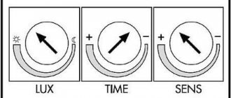
The photo relay can include the following setting controls:
- Response threshold. This setting allows you to increase or decrease the sensitivity of the device. It is recommended to lower its level in winter, especially in snowy weather, to avoid unnecessary reflection of light from the snow, as well as in places with bright street lighting, for example, in megacities.
- A second delay to turn the device on or off. If you increase the turn-off delay, you will be able to avoid false alarms that occur when a random beam hits the photo relay, for example, light from car headlights. Delaying the switch on will prevent the device from reacting to a momentary darkening of the device, for example, from a cloud or the shadows of flying birds.
- Light range control. When connecting a photo relay, using this setting, you can provide the required level of illumination. At its lower limit, the sensor is activated, turning on the power supply, and, conversely, at its upper limit it turns it off. The range can vary from 2 to 100 lux (2 lux – pitch darkness) or from 20 to 80 lux (in this case, 20 lux – deep twilight, when the outlines of objects are barely visible).
Mastering and effectively using the listed settings will help ensure the most optimal operation of the photo relay, eliminating false alarms, thereby making the lighting more comfortable and energy consumption as economical as possible.
The photo relay can include many regulatory settings
Technical specifications
When choosing a suitable device, you should pay attention to its characteristics. You can view the information using the attached passport. The key parameters are:
- Power supply voltage. In the standard version, the device operates from a 220 V network. Choosing options with a voltage of 12 V or 24 V is not the most rational choice due to the need for additional purchase and placement of power supplies.
- Maximum value of switching current. This characteristic becomes important only if the device is used to control a large number of lighting fixtures. For household street lighting systems, the most simple modifications of the device are sufficient.
- The unit startup threshold is measured in lumens and is given as an interval of values. Many models provide the ability to adjust the characteristics.
- Turn-on delay time. Measured in seconds, indicated as an interval of values.
- The shutdown delay time is a similar parameter.
- Required power. Indicated in the form of two indicators: for standby mode and during active operation.
- Protection level: IP65 or IP40. The first category of devices is suitable for installation outdoors, the second - exclusively in a dry room.
Selecting the optimal location for the street lighting sensor
Before connecting the light sensor, you need to decide on its installation location, taking into account a number of important points:
- if the photo sensor is of a remote type, then its location should be in direct reach of daylight;
- sources of artificial lighting should be located as far as possible from the sensor, the main thing is that the relay does not react to their turning on or off;
- It is advisable to exclude as much light from car headlights as possible.
The optimal height for installing the photo relay is from 180 to 200 cm, which will provide the ability to adjust parameters while standing on the ground, without using stools and stepladders.
Some tricks will help you fulfill the above requirements. For example, you can protect the photo sensor from light from street lights using a large-diameter piece of black plastic pipe 15-20 centimeters long. For this purpose, it is necessary to cut the pipe at the bottom at an angle of 40-30° from the vertical wall so that it looks up.
The installation location of the photo relay is selected taking into account a number of rules
Helpful advice! In order to standardize the assembly of devices, special symbols and terms were invented to indicate photo relays on diagrams and drawings. Those who decide to install the device themselves need to know them.
If the relay is designed for one lamp, but of high power, then the ideal place would be to place it directly behind the lampshade. This is where the least amount of random light will fall. It is much easier to configure the sensor if it is located on the east or west side of the building. The main condition for this is the absence of objects with bright light nearby. Therefore, in this case, you need to choose the side where “exposure” is eliminated as much as possible.
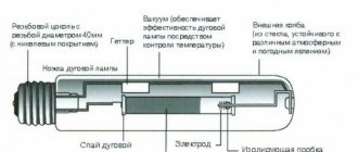
Principle of operation
Scheme:
- The photocell is the main working part in the device. It consists of a tube filled with gas. Inside which the process of ionization and the cathode produces electrons occurs.
- The sensor monitors and reacts to the flow of light (degree of illumination). At dusk, the signal is triggered and the circuit is closed. The light turns on. At dawn, when the flow of light increases, the circuit breaks and the light goes out.
- Sensitivity to light intensity is adjustable. The optimal option for relay operation is selected. The circuit operates on a direct current that responds to the presence or absence of daylight.
Photo relay for street lighting: equipped with additional functions
Both types of photo relays, both with a built-in and remote sensor, have their own varieties. The classification of devices is based primarily on their purpose and additional functional equipment. Both types of devices have subtypes.
Photo relay with motion sensor. Such a device is installed where lighting is required only during human presence, for example, in corridors, in the courtyard of a country house or in a garage. The device responds to movement and heat emitted by the human body.
A photo relay with a motion sensor is installed where lighting is required only during human presence
Photo relay with timer. This option is used when illumination is needed for a certain period of time. Users of the device set the desired time when it turns on or off. Accordingly, the device is equipped with a timer for turning the light on and off. Such sensors are especially relevant in decorative lighting of personal plots or buildings.
An astro timer is not just a photo relay, but a more advanced device programmed for sunrise or sunset in different climatic zones. It is enough to select a specific time zone in memory. The device will automatically operate at the time specified by the program. The price of a photo relay with an astro-timer is much higher, but there is no need to worry about the installation location.
Devices with additional functions are not popular, since the price of a photo relay for street lighting with built-in sensors can be twice as high as the cost of a conventional light-responsive device. Therefore, to provide additional functions, it is not at all necessary to purchase an expensive multiphoto relay; it is enough to buy a regular device and additionally install motion sensors or timers.
An astro timer is a more advanced device programmed for sunrise or sunset
How to choose
An important point in purchasing photo sensors is the correct choice of the required model. As we already found out from the previous section, models come with a remote and built-in sensor. Moreover, each variety has its own technical characteristics. To select the required model, you need to rely on the following selection criteria:
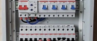
High protection device
- manufacturer. The device often works outdoors, so it must be assembled from high-quality materials that can withstand any weather conditions;
- the presence or absence of the ability to fine-tune. This condition determines how accurately the device can be adjusted to work in a particular area;
- presence or absence of a timer;
- protection of the housing from dust, moisture and mechanical damage. The higher this indicator is, the longer the product will last.
Of course, the most important criterion for many people is the cost of the purchased product, and only then its technical characteristics. But this is not always the right approach. You can always buy a cheap product, but whether it will work well is another question. Therefore, in this situation, it is recommended to give preference to models of medium and high price levels. This is not a case where you can save without consequences.
Connection diagrams for photo relays for street lighting
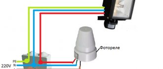
The main function of the photo relay is to supply power at nightfall and turn it off at dawn. Thus, it is an automatic switch that operates without human intervention. The role of the shutdown button is played by a photosensitive element. The photo relay connection diagram is similar: a phase is supplied to the device, it is interrupted at the outputs, and if necessary, the circuit is closed, as a result of which voltage is supplied to the lamps or spotlights.
Related article:
Outdoor LED pole lights: durability and efficiency
Types, technological features of devices, installation specifics. Value for money.
To ensure the operation of the photo relay, power is also required, so a zero is connected to certain contacts. Since the lighting is supposed to be in an open area, there is a need for a ground connection.
It is important to correctly connect the conductors coming out of the body of the regulator itself with the lamp and the network
Helpful advice! To provide additional functions, you can purchase photo relays with motion sensors or timers. However, two separate sensors, for example, for light and motion, will be cheaper to purchase and maintain. In addition, it will be easier to replace a part in one of the two devices than to repair the entire photo relay as a whole.
Unfortunately, there is no universal connection diagram that would fit all types of photo relays, but certain points are typical for all operations. They must be taken into account, especially if you install a photo relay with your own hands.
In almost all models, the output relay has three multi-colored wires that correspond to the following designations:
- black – phase;
- green – zero;
- red – phase commutating to the light source.
To provide additional functions, you can purchase photo relays with motion sensors or timers
Step-by-step instructions for connecting photo relays for street lighting
The instructions below will tell you how to connect the photo relay step by step, quickly and correctly:
- Pre-installation of the distribution panel. It is usually mounted on the wall, and conductors are connected in it.
- Connecting the photo relay according to the diagram, which is in the technical documentation attached to the device itself. Usually a bracket is used as a fastener. It is installed in a place where the relay will receive direct sunlight, but other light sources are isolated.
- Adjusting the system using a controller, that is, selecting the parameters for the device’s response to specific conditions of lighting changes.
- The regulator is installed on the external part of the device with the corresponding technical characteristics: sensitivity range – 5-10 lm; power – 1-3 kW, permissible current threshold – 10A.
If the device is mounted in the middle of an electrical panel with a complex design, where the sun's rays do not penetrate, then the relay and switch are installed separately from each other. The parts of the device are connected to each other with special cables.
The photo relay is connected according to the diagram, which is in the technical documentation attached to the device itself
When installing street lighting, it is recommended to follow the following rules:
- It is better to place a device with an external photocell in such a way as to exclude direct light from the installed lamp. Otherwise, the device will work with errors.
- To check whether the circuit is connected correctly or not, you need to connect the starter to the mains. The result will be clear when the lamp is activated.
Nuances in light sensor connection diagrams
The fact that the photo relay is selected taking into account the expected load may affect the cost of the product: depending on the power, the price increases. Therefore, in order to save money, it is possible to provide power supply not through a photosensor, but through a magnetic starter. This is a special device designed for frequent on/off operation. Using a trigger mechanism allows you to connect power using a photosensitive element with minimal load.
Thus, in fact, only the magnetic starter is turned on, so only the power consumed by it is taken into account. But at the terminals of the magnetic starter it is possible to use a more powerful load.
In order to save money, you can provide power supply not through a photosensor, but through a magnetic starter
Helpful advice! Before installing and configuring the device, it is recommended to carefully study the lighting connection diagram that comes with the device. The document clearly and clearly shows all the wires of the photo relay, and also shows where they need to be connected.
In the case when, in addition to the day/night sensor, it is necessary to connect devices with additional functions, for example, a timer or motion sensor, they are installed after installing the photo relay. In this case, the order of priority of additional devices is unimportant.
If a timer or motion sensor function is provided in the structure of the device, but it is not needed in a particular case, then these devices are simply excluded from the general circuit, that is, no wires are connected to them. In this case, if necessary, these elements of the device can be connected.
Setting up street lighting for a country house
After connecting the photo relay, it is necessary to configure it, taking into account a number of nuances. As mentioned earlier, a photo relay with a built-in photosensor has three wires at the output of the housing. They are connected as follows:
- red, responsible for the electrical load, goes directly to the flashlight, lamp or spotlight;
After connecting the photo relay, it is necessary to configure it, taking into account a number of nuances
- a brown or black wire is connected to the phase coming from the panel;
- The blue wire is connected to zero on the panel body.
An optional, but important point in ensuring safety is the grounding connection. For this purpose, a separate wire is connected to a terminal on the housing. In this case, the cross-section of the wire must be selected in accordance with the power of the expected load of the photo relay. The wiring diagram will tell you how to do this correctly.
The device is configured after its installation. To do this, you need to wait for the moment of natural light when it is desirable to turn on the lamps. Adjust the device using the settings by turning the adjustment wheel. You need to turn it until the light turns on.
It should be noted that the procedure for connecting a relay with a remote sensor is slightly different from connecting a device with a built-in photocell. Here the phase is connected to terminal A1 (L), which is located at the top of the device, then zero is connected to terminal A2 (N). From the output, depending on the location of the wire, the phase is supplied to the lights.
On a photo relay with a built-in photosensor, there are three wires at the exit from the housing
Operating principle and functional purpose
Relays that operate depending on illumination have several names. Among specialists they are simply called light sensors, photo sensors, twilight sensors, etc. In the literature there are definitions of a photosensitive machine or switch. All these names are synonymous and do not even depend on the design of the devices.
The operating principle of a photo relay is based on the operation of a phototransistor or photoresistor, the parameters of which change with changes in illumination . Simply put, the circuit of the microdevice is in an open position until a sufficient amount of light enters it. At a certain level of twilight or darkness, the circuit closes and the lighting device connected to the circuit receives power. Accordingly, when it begins to get light, the opposite happens - the circuit opens and turns off the current supply.
Characteristics and connection features of individual sensor models: photo relay FR 601 and FR 602
The modern domestic market is represented by a wide range of photo sensor models designed for different types and lighting conditions, requiring different lamp powers and the presence of additional functions.
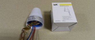
The most popular among standard single-phase models are the FR-601 sensor and its more advanced analogue, the FR-602 photo relay. The manufacturer of the devices is the IEK company. Both types of sensors are characterized by reliability and ease of connection. The differences between the models are insignificant; they operate on current of the same voltage and frequency, and the power consumption is 0.5 W. Externally, the devices are completely identical.
Helpful advice! To connect several lights at the same time, you need to purchase a special controller. This device will receive a signal that controls the lighting.
The only difference is the maximum cross-section of conductors for connection. Model FR-601 is designed for 1.5 mm², and FR-602 – for 2.5 mm². Accordingly, they have different rated load currents. For the FR-601 photo relay it is 10A, for the FR-602 it is 20 A. Both devices have a built-in photocell, and adjustment is allowed in the range from 0 to 50 lux with an interval of 5 lux.
The most popular among standard single-phase models are the FR-601 sensor
Such devices can be built even at home. The main difference between a homemade device and a factory IEK photo relay will be the lack of appropriate protection. This level for production models is IP44, which means protection from dust and moisture. The connection diagram for the photo relay FR 601 and FR-602 is standard and simple. The products last a long time and can withstand a wide range of temperatures.
Among the analogues of this device is the FR-75A model - a photo relay, the circuit of which is more complex for manufacturing at home. The device is less stable and durable in practical use.
Review of popular models
Although light sensors are not a very popular product, nevertheless, manufacturers of electrical products produce similar products, because the struggle to save energy is only intensifying, and their presence is simply very convenient when using outdoor lighting of various directions, but not everyone has yet realized this. The most popular models on the domestic market are shown in the following table; the price of light sensors for street lighting is indicated as of the second quarter of 2019.
| Model | Brand | Specifications | Cost, rubles |
| "FR-601" | "IEK" (China) |
| 220 |
| "FR-602" |
| 280 | |
| "FR-7M" | "Relays and Automation" (Russia) |
| 1 200 |
| "WZM-01/S1" | "ZAMEL" (Poland) |
| 2 500 |
| "SNS L 07" | "Elektrostandard" (Russia) |
| 530 |