Transformers 10/0.4 kV in rural and urban electrical distribution networks
10/0.4 kV transformers in rural and urban electrical distribution networks up to and including 0.63 MB-A are usually protected by fuses on the 10 kV side and very often also by fuses on the 0.4 kV side.
A combination such as fuses on the 10 kV side and circuit breakers on the 0.4 kV side is also possible (§ 5). On the HV side of closed substation transformers (ZTS), fuses are used in combination with load switches (LSBs) - automatically driven disconnectors that are turned off when the fuse trips on at least one of the phases.
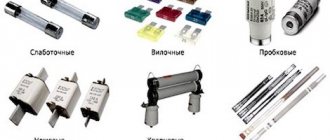
A fuse is a switching device designed to disconnect the protected circuit by melting special current-carrying parts (fuse links) under the influence of a current exceeding a certain value, followed by extinguishing the resulting electric arc.
ORGANIZATION OF WORK PRODUCTION.
Work on recharging fuses with spiral fuse links is carried out in the following sequence:
4. 1. Disassembling the fired cartridge:
4. 1. 1. Unsolder one of the cartridge covers and remove it. 4. 1. 2. Unsolder the cover from the second cap and remove it.
4. 2. Preparation of elements and assembly of the cartridge:
4. 2. 1. Release the holes in the intermediate washers and the caps of the unburnt ends of the fusible wires by unsoldering and removing them. 4. 2. 2. Clean the intermediate washers and cartridge caps from solder and tin the ends of the cap. 4. 2. 3. Wipe the cartridge tube inside and outside with a clean rag soaked in gasoline. In this case, no lint from the rag should remain on the surface of the tube. 4. 2. 4. Check by visual inspection and tapping that there are no cracks on the cartridge tube. Tubes with microcracks must be rejected. 4. 2. 5. Check the condition of the reinforcement of the caps on the tube. Tubes with damaged reinforcement must be rejected. 4. 2. 6. Check the compliance of the fuse-link taken for charging with the passport data, checking it with the data in the table. No. 2. 4. 2. 7. Stretch each fuse wire twisted into a spiral so that its length is 0. 7-0. 8 cartridge lengths. Squeeze the loops at both ends of each fusible wire and bend them into a hook shape so that the end is 6-10 miles from the spiral part of the wire. 4. 2. 8. Tin the annular surface of the indicator cover, which will be adjacent to the cap. 4. 2. 9. Dry the quartz sand for 2-3 hours at a temperature of 105-1300 C, stirring it occasionally.
4. 3. Loading cartridges:
4. 3. 1. Insert the required number of fusible links into the tube one by one and attach them to the cap in the sequence indicated below:
- insert the fuse-link by the hook-shaped end inside the tube and insert the bent end of the wire into one of the holes in the intermediate washer or cap.
- turn the tube over, holding the wire against the washer with your finger, hook the loop on the second end of the wire with a steel hook, pull out the spiral so that only the loop on the wire protrudes from the tube and thread it through the hole in the intermediate washer. To avoid residual deformations and sagging of the spiral, it should not be excessively pulled out of the tube.
4. 3. 2. Fix the number of fusible wires required for the rated current in the tube and solder their ends to intermediate washers or caps. 4. 3. 3. Straighten the spirals with a steel hook so that they are parallel and their axes are located along the line connecting the edges of the internal openings of the intermediate washers. 4. 3. 4. Insert a charged trigger indicator into the tube from the opposite side of the tube, hook the indicator wire into the loop and remove it from the tube. Thread a copper wire (clamp) with a diameter of 0.4-0 into the loop of the index wire. 5 mm and about 100 mm long and solder it to the intermediate washer at two diametrically located points. 4. 3. 5. Shorten the clamp so that the remaining part is covered by the lid. 4. 3. 6. Fasten the index wire, and then solder the index cap to the cartridge cap. Soldering must be continuous (without gaps). 4. 3. 7. Turn the cartridge over and fill it to the top with dry quartz sand. Backfill in a thin stream and ensure that the sand is slightly compacted. 4. 3. 8. Solder the lid to the cap around the circumference. 4. 3. 9. Paint the ends of the cartridge and the outer part of the reinforcement with red enamel paint. Fuses with ceramic cores are recharged in the same way.
4. 4. Organization of work on recharging the PN-2 fuse:
4. 4. 1. Unscrew the two screws securing the contact washer of the conductive knife to one of the cartridge covers. 4. 4. 2. Unscrew the four screws securing either of the two cartridge covers to the body and remove the cover along with the asbestos gasket and the current-carrying knife. 4. 4. 3. Pour the sand with the remains of the burnt fuse into a specially prepared box. 4. 4. 4. Unscrew the two screws securing the second contact washer of the current-conducting knife and remove it from the cartridge (housing). 4. 4. 5. Wipe with a clean rag soaked in gasoline inside and outside the cartridge body. 4. 4. 6. Check by visual inspection and tapping that there are no cracks on the cartridge body. Cases that have at least microcracks must be rejected. 4. 4. 7. Clean the edges of the contact washer of the current-conducting knives from remnants of the fuse-link. 4. 4. 8. Weld the fusible insert to the edges of the contact washer using electric contact spot welding (or fusible tin) in accordance with table. No. 3. 4. 4. 9. Insert the contact blade into the hole in the housing cover and secure it with two screws. 4. 4. 10. Pour dry quartz sand into the housing with an asbestos gasket and attach it to the body of the cartridge (body) with four screws, then secure the contact washer with the knife with two screws on the housing cover.
Operating principle and types of fuses
The fuse as a protective device has been used in electrical networks for more than 100 years. His work is based on the well-known Joule-Lenz law (1841), according to which the passage of electric current through a conductor is accompanied by the release of heat Q (in joules):
Joule-Lenz law
The fuse link is a section of the protected electrical circuit that has a smaller cross-section and a higher resistance R than the other elements of this circuit. Therefore, when a short-circuit current passes through the circuit, the fuse-link heats up more than other elements of the protected circuit, melts earlier and thereby saves the electrical installation from overheating and destruction. But to stop the passage of the short-circuit current, i.e., to disconnect the electrical installation from the supply network, melting the insert is not enough; it is also necessary to extinguish the electric arc that has arisen in this place. Quickly extinguishing the arc is the most important task of a fuse. According to the method of extinguishing the electric arc, fuses used to protect transformers are divided into two main groups:
- fuses with tubes made of gas-generating material (fiber or vinyl plastic), which abundantly emits gases at the high temperature of the electric arc; the high pressure that occurs at this moment (in PR-type fuses with voltages up to 1000 V) or longitudinal blast (in PSN fuses with voltages above 1000 V) ensure rapid extinguishing of the electric arc;
- fuses with filler (quartz sand), in which the electric arc is extinguished in a small-diameter channel formed by the body of the evaporated fuse link, between grains (granules) of quartz sand; Such fuses are usually called quartz fuses.
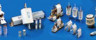
On the 10 kV side of transformers, mainly quartz fuses of the PC type are installed, on the 0.4 kV side - also mainly quartz fuses of the PN-2 type are installed. Quartz fuses have several important positive properties: they have a current-limiting ability (due to the very rapid extinguishing of the electric arc, the short-circuit current is not manages to reach its maximum amplitude value); fusible inserts are protected from the external environment by quartz sand and a hermetically sealed porcelain tube, so they do not age for a long time and do not require replacement; The design of fuses PC and PN-2 provides for tripping signaling, and the contacts of the signaling device can give a command to turn off the three-phase load switch, which prevents the possibility of the transformer operating in half-phase mode.
By using factory-made quartz fuses with correctly selected parameters, it is usually possible to ensure selectivity between the fuses on the HV and LV sides of the transformer, or at least between the fuses on the HV side of the transformer and the protective devices on the LV outgoing lines, i.e. allow the transformer to be disconnected from the supply network in the event of a short circuit on the LV busbars or on any of the outgoing LV lines.
Types of microwave fuses
There are three different types of fuses in a microwave oven - one mains fuse and two high-voltage ones.
A high-voltage fuse for a microwave oven serves as protection for an element such as a magnetron. This is a high-voltage transformer that needs protection. The protective element itself is located structurally next to it, but if you pay attention to the diagram, you will notice that it opens the circuit between the input and output of the high-voltage unit.
As for the second fuse of a similar type, it is available only in those microwave ovens that have an electronic control panel. In this case, such a panel should be powered by a small low-power transformer. He will be responsible for converting the electrical current from the home network into the voltage required for the panel to operate.
Selecting the rated current of the fuse link
A high-voltage fuse protects the high-voltage winding of a power transformer not only from short circuits, but also from overload, therefore, when choosing a fuse link, the rated operating current must also be taken into account.
When choosing the current rating of a fuse link, several factors must be taken into account.
- Firstly, the power transformer may be subject to short-term overloads during operation.
- Secondly, when the transformer is turned on, magnetizing current surges occur that exceed the rated current of the primary winding.
It is also necessary to ensure selectivity of work with protection installed on the low voltage (LV) side and on the outgoing consumer lines. That is, first of all, the circuit breakers (fuses) on the low-voltage side of the outgoing lines that go directly to the load to consumers should operate.
If this protection does not work for one reason or another, then the input circuit breaker (fuse) of the LV side of the power transformer must operate. The fuses on the HV side in this case are redundant protection, which should operate in the event of an overload of the low voltage winding and failure of the protection on the LV side.
Based on the above requirements, the fuse link is selected based on twice the rated current of the high voltage winding.
Thus, high-voltage fuses installed on the HV side protect the section of the electrical circuit before the transformer input from damage, as well as from internal damage to the power transformer itself. And fuses (circuit breakers) on the LV side of the power transformer protect the transformer itself from overloads above the permissible limit, as well as from short circuits in the low voltage network.
The rated current of the power transformer windings is indicated in its passport data.
Microwave fuses
A high-voltage fuse for a microwave is as necessary as in any other network with expensive equipment. Microwave ovens are quite complex household devices in their design. The metal structure of the fuse for this device is as follows: a metal thread in the role of a fusible insert, which is located in a glass flask, as well as special tips at the ends of the flask to make it convenient to install the protective device. If the current value reaches the nominal value, the metal thread begins to heat up. The heating rate increases with increasing current flow. When the filament temperature reaches a certain value, the filament breaks, causing the entire device to be de-energized.
Selecting fuses to protect power transformers
The main conditions for choosing fuses for power transformers are the following parameters. The rated voltage of the fuses and their fuse links must be equal to the rated mains voltage:
Unom pr = Unom
Fuses in the USSR were produced at rated voltages corresponding to GOST 721-77, including 6; 10; 20; 35; 110 kV. The rated voltage is indicated in the name of the fuse, for example PK-6, PK-10, PSN-10, PSN-35, etc.
Installing a fuse intended for a lower voltage network, i.e. creating the condition Unom pr < Unom. c is not allowed to avoid short circuit. due to the fuse insulation being blocked. At the same time, it is not allowed, without special instructions from the manufacturer, to use a fuse in networks with a lower rated voltage due to the risk of overvoltages when disconnecting the short circuit. The rated breaking current of the selected fuse must be equal to or greater than the maximum short-circuit current. at the fuse installation location:
As applied to power transformers, current/k. max is calculated for a three-phase short circuit. at the high voltage terminals of the transformer, i.e. where the fuses are installed. In this case, the mode of the supply system is assumed to be maximum, which corresponds to the lowest resistance of the supply system to the point of connection of the transformer in question. The recharge of the short circuit area should also be taken into account. electric motors connected in the same section as the transformer in question. Rated shutdown currents are indicated in GOST and factory information.
Fuses with voltages over 1000 V are available with a rated shutdown current from 2.5 to 40 kA (GOST 2213-70). (The previous name for the rated breaking current was the maximum breaking current.)
Selection of 10 kV fuses for transformer protection
- By rated voltage: i.e. the rated voltage of the fuse Unom.pr must correspond to the rated network voltage: Unom = Unom.s
- According to the rated shutdown current: Iо.nom >= Iк.max i.e. the rated shutdown current of the fuse according to its rating data must be greater than or equal to the maximum value of the short-circuit current. at the location where the fuse is installed. When calculating short-circuit currents. it is necessary to take into account the recharge of the short circuit area. electric motors.
- According to rated current. The rated current of the fuse is equal to the rated current of the element being replaced. A replaceable fuse element with a fine-grained filler, for example a PC type, is considered to be a cartridge (one or more) with quartz sand, a fusible element, an operation indicator or an impact device, assembled in a factory.
The rated current of the fuses protecting power transformers on the 10 and 0.4 kV sides is selected from the table
Recommended values of rated currents of fuse links 1nom fuses for three-phase power transformers 6/0.4 and 10/0.4 kV
| Rated current, A | ||||||
| Transformer power, kV* A | transformer on the side | fuse link on side | ||||
| 0.4 kV | 6 kV | 10 kV | 0.4 kV | 6 kV | 10 kV | |
| 25 | 36 | 2,40 | 1,44 | 40 | 8 | 5 |
| 40 | 58 | 3,83 | 2,30 | 60 | 10 | 8 |
| 63 | 91 | 6,05 | 3,64 | 100 | 16 | 10 |
| 100 | 145 | 9,60 | 5,80 | 150 | 20 | 16 |
| 160 | 231 | 15,4 | 9,25 | 250 | 32 | 20 |
| 250 | 360 | 24,0 | 14,40 | 400 | 50 | 40 |
| 400 | 580 | 38,3 | 23,10 | 600 | 80 | 50 |
| 630 | 910 | 60,5 | 36,4 | 1000 | 160 | 80 |
Note It is assumed that fuses of the PN-2 type are used on the 0.4 kV side, type PK-6 on the 6 kV side, and type PK-10 on the 10 kV side.
Fuses for protecting the voltage transformer on the HV side
Voltage transformers of 110 kV and above are protected only on the low voltage side by automatic circuit breakers or fuses. For voltage transformers of 6, 10 and 35 kV, current calculation for the fuse link is not carried out.
The fuse for protecting the voltage transformer on the HV side is selected only according to the voltage class. For each voltage class, special fuses of the PKN (PN) type are produced - 6, 10, 35 (depending on the voltage class); they are used exclusively to protect voltage transformers.
Disadvantages of fuse-based transformer protection
Protection with fuses is structurally the simplest, but has disadvantages - instability of protection parameters, which can lead to an unacceptable increase in the protection response time for certain types of internal damage to power transformers. When protecting with fuses, difficulties arise in coordinating the protection of adjacent sections of the network.
Video: High voltage fuses
We recommend:
- Operating principle of transformer differential protection
Transformer protection with fuses
Border and maximum switchable currents
There are fuse links in high-voltage equipment that will burn out the moment their maximum temperature is reached. Most often, such protective devices are called border protection devices. Naturally, if the boundary current is close in value to the rated value or slightly greater than it, then in this case the fuse element is able to operate normally at its parameters.
There is another important parameter, which is called the maximum cut-off current. In this case, we are talking about the maximum current value that the selected fuse element can turn off.
It is important to know here that this value should be either equal to or slightly greater in value than the maximum possible short circuit current in the protected circuit. If you choose the wrong fuse based on this parameter, then the duration of the arc may be too long, which will lead to the destruction of the cartridge of the device itself, and not just the fusible element.
for “Protection of transformers with fuses”
- Den
:V
Tell me, what fuse to install to protect a 6kV 630kVA transformer?
Answer
Valery Gennadievich Stulov
:
V
For a 630KVA transformer it is necessary to install 80A fuses
Answer
:
V
First you need to calculate the current consumption. I got about 110A taking into account the overload. Select PKT 101-6-160-31.5U3 P - fuse; K - with quartz filler; T - for power transformers; 1 - single-pole, with operation indicator; 01 — contact design; 6 - rated voltage in kilovolts; 160 - rated fuse current in amperes; 31.5 - rated shutdown current in kiloamperes; U—climatic version; 3 – accommodation category.
Answer
:
V
How to choose a high-voltage fuse KTP 630 kVA, 10\04 kV, KTP 10\0.4 kV 400 kVA, KTP 250 kVA 10\0.4 kV
Answer
:
V
If the type of transformer is known, then the easiest way is to find the current and calculate the current for the fuse link, using reference data on power transformers from one of the manufacturers, since all transformers are produced, as a rule, according to a standard range of rated powers and, accordingly, with similar characteristics.
Answer
:
V
Hello! Tell me how to quickly calculate the current for a fuse link if only the rated power of the power transformer is known?
Answer
- Admin
:
V
Use the transformer reference data. Or you can use the above table of recommended values for the rated currents of fuse links for three-phase power transformers 6/0.4 and 10/0.4 kV:
Answer
