June 19, 2019
resource accountinglighting engineeringresponsible applicationsuniversal applicationLittelfusearticlepassive EC and electromechanical fuses
Vyacheslav Gavrikov (Smolensk)
Littelfuse product range contains a wide range of fuse : from traditional glass and ceramic to automotive and SMD fuses .
The idea of using a fuse link for short circuit protection was proposed back in the 19th century. The first fuse, created in 1890 in Edison's laboratory, was an open design based on a light bulb with a fuse-link made of wire. The more familiar form and concept of replaceable protective components was realized in 1914 with the introduction of general purpose fuses and automotive fuses. Littelfuse is not only one of the leaders, but also one of the pioneers in this market segment. The first low-voltage Littelfuse fuses were introduced back in 1927. The company now produces a wide range of models: traditional glass and ceramic, film, automotive and SMD fuses, as well as other protection elements, in particular self-resetting fuses.
This article provides an overview of general purpose Littelfuse fuses and specialty fuses for explosive applications.
Regulations
Safety is a critical factor both in production processes and in people's daily lives. Therefore, fuses must necessarily meet the stringent requirements of existing safety standards. Any official manufacturer indicates what safety standards its products meet.
Different countries have their own regulatory bodies and regulations. For the domestic market, IEC standards are primarily of interest. In particular:
- GOST R IEC 60127-1-2005 Miniature fuses. Part 1: Terminology for fuses and general requirements for miniature fuse links;
- GOST IEC 60127-2-2013 Miniature fuses. Part 2. Tubular fuse links;
- GOST IEC 60127-3-2013 Miniature fuses. Part 3. Subminiature fusible links;
- GOST IEC 60127-4-2011 Miniature fuses. Part 4. Universal modular fuse-links for volumetric and surface mounting;
- GOST 30801.5-2012 (IEC 60127-5:1989) Miniature fuses. Guide to Certification of Miniature Fuse Links;
- GOST IEC 60127-6-2013 Miniature fuses. Part 6. Fuse holders with miniature fuse link.
According to GOST R IEC 60127-1-2005, a fuse is a device that, by melting one or more of its parts having a certain design and dimensions, opens the circuit in which it is connected, interrupting the current if it exceeds a specified value for a certain time. The same standard presents the characteristics of fuses and general requirements for them.
Types and device
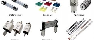
Depending on the tasks being solved, the classification of fuses can be as follows (Figure 5):
- blade guards;
- low-current fuse links;
- plug fuses;
- quartz;
- cork type
- gas generating.
Rice.
5. Types of fuses There are also self-resetting fuses, inertia and flip-out fuses (Fig. 6). Inertia-type products are designed to protect electric motors, which create heavy loads when starting. Fusible elements heat up but do not burn out. After the engine starts, the slow-blow fuse goes into standby mode.
Folding inserts are used to protect power lines. In emergency situations, the fusible element opens the circuit. Under the influence of high temperature, the insert elongates, resulting in pressure on the trigger mechanism, which throws the fuse out of its socket. This ensures reliable shutdown of the emergency section.
Rice. 6. Flip-up fuses
The design of a self-resetting fuse differs from other types of electrical devices. The working element of the product is a polymer with a positive temperature coefficient of expansion. The polymer contains carbon inclusions that conduct current.
When heated, carbon bonds are broken, resulting in an increase in electrical resistance. When the melting temperature of the polymer is reached, the resistance tends to infinity, that is, the circuit opens. When cooled, the electrical conductivity of the polymer resumes. The fuse is self-resetting.
Main characteristics of fuses
The average user, when choosing a fuse, focuses only on the form factor, current rating and operating voltage. However, from the developer’s point of view, everything turns out to be much more complicated, since he has to take into account all the features of the fuses and their operating conditions. Let's look at a set of basic characteristics of fuses.
Ampere-second characteristic . The most important and informative characteristic of a fuse is not the current rating at all, but the ampere-second characteristic, which is a curve of actual tripping time versus expected AC/DC current under specified tripping conditions [1]. As an example, Figure 1 shows the ampere-second characteristic of the 438 from Littelfuse.
Rice. 1. Ampere-second characteristic of 438 series fuses
The ampere-second characteristic indicates that the fuse is not an ideal element and has significant inertia - for it, the response speed depends on the current strength. The higher the current, the faster the fuse link will melt. In particular, from Figure 1 it can be seen that a fuse with a current rating of 0.25 A, even at a current of 0.6 A, will trip only after 10 seconds, and at a current of 1 A, the response speed will be about 4 ms.
Based on the type of ampere-second characteristic, GOST R IEC 60127-1-2005 divides fuses into the following types [1]:
- FF – ultra-fast fuse links;
- F – high-speed fuse links;
- M – semi-delayed fuse-links;
- T – delayed fuse links;
- CT – super-slow fuse links.
It is important to understand that inertia and delay in fuse operation are not always bad. The fact is that in many applications there are “standard” current overloads. For example, turning on a powerful power source is accompanied by significant inrush currents associated with charging the output capacitance of the source itself and the load capacitances. However, in the future, the current consumption of the same power source turns out to be significantly lower. Thus, the “slow” fuse will not have time to operate and will miss the starting overload, but if a permanent short circuit occurs in the circuit, it will safely protect the circuit.
The ampere-second characteristic has a very unpleasant feature, which follows from the definition presented above. The fact is that it is given for “established trigger conditions.” Under the triggering conditions, first of all, it is worth understanding the ambient temperature and the quality of heat removal from the fuse link.
The current rating , specified by the manufacturer, characterizes a certain amount of current that a fuse-link can carry without melting for a given time. For example, for 438 series fuses, the trip time at rated current is at least 4 hours.
Temperature dependence of the operating current . The fuse trips when the temperature of the fuse link reaches its melting point. Obviously, the higher the ambient temperature, the less energy is required to heat the fuse link. In other words, the higher the temperature of the environment, the lower the current at which the fuse will trip.
As an example, Figure 2 shows the temperature dependence of the current rating for the 438 series SMD fuses from Littelfuse. The graph shows that the change in current rating over the entire operating temperature range -55..150°C is ±35%.
Rice. 2. Temperature dependence of current rating for fuses of the 438 series
One important note needs to be made here. The Littelfuse fuse selection guide [2] explicitly states that designers should not confuse ambient temperature with room temperature. The fact is that the temperature of the environment that directly surrounds it is important for the fuse. It is quite obvious that, for example, when the power source is operating, transistors and other power components heat up. This heating leads to an increase in the temperature of the air inside the case. As a result, the ambient temperature for the fuse inside the housing will be significantly higher than outside.
In addition, do not forget about the reverse heat transfer process. The fuse has a resistance and heats up due to ohmic losses I2R. Some of the heat can be removed by the circuit board or air circulation. Obviously, the better the quality of the heat sink, the more energy will be required to heat the fuse-link to the operating state. This is especially important for SMD components.
I2t (Joule integral) . The ampere-second characteristic has another drawback. It is driven for direct or sinusoidal alternating current, but in many applications the fuse protects circuits that carry pulsed currents of various shapes. To calculate the energy released in the fuse, use the Joule integral I2t.
I2t (Joule integral) – the integral of the square of the current over a certain period of time. I2t, expressed in amperes per square second (A2×s), is equal to the energy in joules deposited in a 1-ohm resistor in a circuit protected by a fuse [1].
I2t calculation is an important parameter when selecting a fuse. The fuse selection technique is described in detail in the next section.
Breaking capacity of a fuse-link . The higher the short-circuit current, the faster the fuse will operate. However, if the current increases too much, the fuse link may degrade too quickly, resulting in damage to the component's housing. In some cases, the fuse will simply blow. For this reason, for each fuse, the manufacturer indicates the breaking capacity - the value of the expected current (with alternating current, the effective value) that the fuse link is capable of turning off at the set voltage and given operating conditions [1].
Voltage rating . When the fuse trips, the electrical circuit is physically open. However, with a significant increase in voltage, breakdown may occur (through the air, through the body, and so on). For this reason, the voltage rating must be indicated in the documentation for fuses.
Taking into account all of the above, it becomes clear that choosing the optimal fuse is not so simple. On the one hand, the developer must calculate I2t for a given current, take into account the temperature dependence and select a suitable model, and on the other hand, it is mandatory to carry out field tests to take into account all the features of the thermal behavior of the fuse as part of the final device.
List of components
Electricians designate switches, generators, starters and other electrical components on the diagrams, adhering to the requirements of ESKD standards. Specialists pay special attention to electrical diagrams, which display devices with electrical interconnections.
To correctly read the diagram, you must first familiarize yourself with the included components and components. The principle of their operation and the device itself are studied separately. Information on the use of circuit elements is indicated in reference books and manuals.
The relationship between components and GOST symbols in electrical circuits is established due to their positions. To construct conditional graphs, standard geometric symbols are used. Their separate or combined use is possible. The meaning of the image depends on the geometric symbol with which it is combined.
Electrical engineers use a standard system for graphically indicating ERE in electronic devices and electrical circuits. It applies to all components, conductors and connections between them. For products of the same type, a positional system is used, which is based on:
- letter designation of electrical circuit elements;
- type of construction;
- ERE number.
Fuse selection
The choice of fuse is determined by the initial data and features of a particular application [1]:
- Rated current . The circuit's current rating determines the fuse's current rating. To protect against unplanned operations, it is recommended to use a current reserve of 25%. For example, if the rated current of the circuit is 7.5 A, then, taking into account the margin, you should select a fuse based on a current value of 10 A.
- Operating temperature also greatly influences the choice of fuse current rating, so additional margin is necessary for proper operation. For example, if 438 series fuses are expected to operate at a temperature of 75°C, then the margin should be about 15% (see Figure 2).
Let's look at an example. Let's say a 438 series fuse must operate at a temperature of 75°C and a rated current of 1.5 A. Obviously, taking into account points 1 and 2, a fuse with a rating of 1.5 A will not be enough for normal operation. The required current rating with a margin is: 1 .5 A/(0.75 × 0.85) ≈ 2.4 A → 2.5 A (closest rating).
- Operating voltage . The fuse voltage rating must be greater than the maximum possible voltage in the circuit.
- Response speed . Based on the response speed, fuses are divided into five types (FF - super-fast, F - fast, M - semi-slow, T - slow, TT - super-slow). The choice of a specific fuse should be made taking into account the ampere-second ratings provided by the manufacturer.
- Maximum short circuit current . To prevent the fuse from melting or exploding, its breaking capacity must be greater than the maximum short-circuit current.
- Requirements for dimensions, standard size and installation method . There is now a wide range of fuses available for surface mounting, through-hole mounting and for mounting in special holders. The choice of a specific series is determined by the characteristics of each specific application.
- Compliance with standards . The use of a particular fuse is permitted only if it is certified and meets the requirements of established standards. In addition to the GOST R IEC 60127 group of standards, there are other standards. For example, to operate in explosive atmospheres, the fuse must comply with the provisions of GOST 31610.11-2014 (IEC 60079-11:2011) “Explosive atmospheres. Part 11. Equipment with type of explosion protection “intrinsically safe electrical circuit “i” (with Amendment)”.
- Resistance to impulse influences . This point should be discussed in more detail.
This data is sufficient to select a fuse operating in a circuit with a constant or variable sinusoidal current load, if this load does not exceed the current rating of the fuse. However, there are many applications in which the load is pulsed. We are talking about starting currents and various transient processes. In such applications, the fuse must be able to withstand momentary current surges in excess of its current rating without tripping.
To determine whether a fuse will trip or not trip when a given number of current pulses occurs, use the Joule integral I2t, which can be calculated manually or using special utilities. Let's consider each method separately.
Why are they needed?
Every modern car is equipped with an on-board network, the voltage of which is designed for 12V or 24V. The electrical wiring harness consists of a set of individual wires, where there is colored insulation, with the help of which the purpose of the cable is determined. A copper core is designed to connect elements with permissible power. When a short circuit occurs, metal melts or wiring ignites.
By using various types of automotive fuses, you can avoid an uncontrolled increase in current, as well as reduce the likelihood of an emergency.
I2t fuse calculation
When doing manual calculations, you first need to decide on the shape of the pulses. Next, taking into account the shape of the current, determine the value of the integral I2t for one pulse. For standard-shaped pulses, there are simple calculation formulas (Figure 3) [1].
Rice. 3. Calculation of I2t for pulses of various shapes
For example, if rectangular current pulses are assumed to flow (Figure 3 a) with amplitude Ip = 1 A and duration t = 5 ms, then I2t (pulse) is calculated using formula 1:
$$I^2t\:(pulse)=I_{p}^2t=1^2\times 0.005=0.005\:A^2c\qquad{\mathrm{(}}{1}{\mathrm{)}} $$
Next, you need to take into account the number of pulses. To do this, consider Figure 4 [1]. Suppose that 6000 pulses are expected to pass, then from the graph we can determine the nominal value I2t of the fuse (formula 2):
$$I^2t\:(fuse)=\frac{I^2t\:(pulse)}{0.3}=\frac{0.005\:A^2c}{0.3}=0.016\:A^2c\qquad{ \mathrm{(}}{2}{\mathrm{)}}$$
The resulting value must be greater than the value specified in the documentation. Otherwise, the fuse will trip when a sequence of pulses occurs.
Rice. 4. Taking into account the number of pulses when calculating the required I2t for the fuse
Manual calculation of I2t and determination of current reserves are not complex operations, but to simplify the work, you can use the online utility Littelfuse iDesign Tool, which allows you to select the appropriate fuse in a few mouse clicks.
Decoding the VAZ 2109 relay (old style mounting block)
1 – Performance of the front optics cleaning elements
2- Rear window washer motor performance
3- Protection against breakage of turn signal and light signaling lamps
4- Protection against failure of the windshield wiper motor
5- Allows you to determine the performance of the lamp
6- Rear window defogger overvoltage protection
8- High beam lamps
9- Low beam lamps
11- Responsible for the operation of the engine cooling fan. If this relay fails, the risk of engine overheating increases.
12- Klaxon operation
Using Littelfuse's online fuse selection tool
Littelfuse iDesign Tool is an online utility that simplifies the selection of the optimal fuse and automates the calculations of current and I2t margins. In addition, the utility allows the developer to specify an arbitrary pulse shape when determining I2t.
The fuse selection process is broken down into seven steps.
Step 1 . First, the user must set the initial conditions for the calculation: maximum operating voltage, rated current, maximum short-circuit current, maximum operating temperature (Figure 5). The utility also offers to select the area of application of the fuse (telecommunications, military electronics, and so on). Unfortunately, there are currently no specialized fuse models available in the online utility. When selecting, for example, explosive fuses, the utility will simply redirect the user to the appropriate page of the site, and the selection will need to be made manually.
Rice. 5. Step 1. Definition of initial data and requirements
Step 2 . In the second step, it is necessary to select the standards whose requirements the fuse must meet (Figure 6).
Rice. 6. Step 2. Select standards
Step 3 . At this stage, the user is asked to select the type of fuse: SMD, lead-in for soldering into holes, for installation in a holder, with radial leads, with axial leads (Figure 7).
Rice. 7. Step 3. Select fuse type
Step 4 . Taking into account the previously specified data and requirements, the program automatically selects the appropriate series of fuses. The user must select one of the proposed options (Figure 8).
Rice. 8. Step 4. Series selection
Step 5 . Determination of the shape and parameters of current pulses for calculating I2t. In this case, the user has three options. The first option is suitable for calculating the fuse’s resistance to standard-shaped pulses (Figure 9).
Rice. 9. Step 5. Setting the parameters of standard pulse shapes for calculating I2t
Step 6 . The second option involves determining the shape of pulses of arbitrary shape by points and further automatic calculation of I2t (Figure 10).
Rice. 10. Step 6: Define Basic Requirements
Step 7 . If the user has already calculated the I2t value manually, then it can be set directly (Figure 11).
Rice. 11. Step 7: Define Basic Requirements
Step 8 . Taking into account the previously specified data and requirements, the program automatically selects the most suitable fuse models. The user must select one of the proposed options (Figure 12).
Rice. 12. Step 8: Determine Basic Requirements
Step 9 . Checking the speed of the fuse (desired response time) at a given short-circuit current. At this stage, the program automatically builds ampere-second characteristics taking into account previously defined parameters. The user just has to make sure that the selected fuse is fast enough. If necessary, you can go back a few steps and easily repeat the calculations with another series or model of fuse (Figure 13).
Rice. 13. Step 9: Determine Basic Requirements
Decoding the relay in the fuse block of the new VAZ 2109 model
K1 Without it, the rear window washer motor will not work K2 Responsible for the operation of the turn signal lamps and light signaling K3 Ensures the operation of the windshield wiper K4 Protects the brake light lamps and the dimensions of the car K5 Ensures the operation of the high beam lights K6 Ensures the operation of the optics washer device K7 Protects the electric window motor, if they are installed on your car K8 Sound signal or just a horn K9 Protects against increased voltage going to the engine cooling system fan K11 Responsible for the operation of the rear window heating device K12 Ensures the operation of low beam lights
Well, we have all looked at the pinout and decoding of the fuse box on a VAZ 2109 car. I would also like to note that in most cases there is almost always a diagram of fuses and relays on the body or on the cover of the mounting block, so I think it won’t be difficult to figure out this issue. Bye everyone.
Review of Littelfuse fuses
Littelfuse is one of the leaders in the field of fuses. The company's product range includes SMD fuses, fuses with radial and axial leads, as well as fuses of various specialized series and models.
SMD fuses are in demand primarily in low-voltage applications, where compact dimensions play a key role. In addition, they significantly simplify the installation process, since they are soldered together with other SMD components onto a printed circuit board. Additional benefits of SMD fuses include high speed, low resistance, and a wide range of current ratings.
Currently, Littelfuse offers almost forty series of SMD fuses with different characteristics (Figure 14, Table 1):
- with a current rating of 0.62...40 A;
- with voltage ratings up to 600 V;
- with TT, F and FF speed;
- with standard size from 0402;
- with operating temperature range -55…150°C.
Rice. 14. SMD fuses from Littelfuse
Table 1. Characteristics of Littelfuse SMD fuse series
| Type | Name | Ampere-second characteristics | Frame | Current rating, A | Voltage rating, V | Breaking capacity, A | Operating temperature, °C | ||
| TT | F | FF | |||||||
| Ceramic | 437 | – | + | – | 1206 | 0,25…8 | 125/63/32 | 50 | -55…150 |
| 438 | – | + | – | 0603 | 0,25…6 | 32/24 | 50 | ||
| 440 | – | + | – | 1206 | 1,75…8 | 32 | 50 | ||
| 441 | – | + | – | 0603 | 2…6 | 32 | 50 | ||
| 469 | + | – | – | 1206 | 1…8 | 24/32 | 24…63 | ||
| 501 | – | + | – | 1206 | 10, 12, 15, 20 | 32 | 150 | ||
| Thin film | 466 | – | – | + | 1206 | 0,125…5 | 125/63/32 | 50 | -55…90 |
| 429 | – | – | + | 1206 | 7 | 24 | 35 | ||
| 468 | + | – | – | 1206 | 0,5…3 | 63/32 | 35…50 | ||
| 467 | – | – | + | 0603 | 0,25…5 | 32 | 35…50 | ||
| 494 | + | – | – | 0603 | 0,25…5 | 32 | 35…50 | ||
| 435 | – | – | + | 0402 | 0,25…5 | 32 | 35 | ||
| Nano2® Fuse | 448 | – | – | + | 2410 | 0,062…15 | 125/65 | 35…50 | -55…125 |
| 449 | + | – | – | 2410 | 0,375…5 | 125 | 50 | ||
| 451/453 | – | – | + | 2410 | 0,062…15 | 125/65 | 35…50 | ||
| 452/454 | + | – | – | 2410 | 0,375…12 | 125/72 | 50 | ||
| 456 | + | – | – | 4012 | 20, 25, 30, 40 | 125 | 100 | ||
| 458 | – | + | – | 1206 | 1,0…10 | 75/63 | 50 | ||
| 443 | + | – | – | 4012 | 0,5…5 | 250 | 50 | ||
| 464 | – | + | – | 4818 | 0,5…6,3 | 250 | 100 | ||
| 465 | + | – | – | 4818 | 1…6,3 | 250 | 100 | ||
| 462 | + | – | – | 4118 | 0,500…5 | 350 | 100 | -40…80 | |
| 485 | – | + | – | 4818 | 0,500…3,15 | 600 | 100 | -55…125 | |
| Telelink® Fuse | 461 | – | – | – | 4012 | 0,5…2,0 | 600 | 60 | -55…125 |
| 461E | – | – | – | 4012 | 1,25 | 600 | 60 | ||
| OMNI-BLOK® | 154 | – | – | + | * | 0,062…10,0 | 125 | 35…50 | -55…125 |
| 154T | + | – | – | * | 0,375…5 | 125 | 50 | ||
| Fuses with holder | 157 | – | – | + | * | 0,062…10 | 125 | 35…50 | -55…125 |
| 157T | + | – | – | * | 0,375…5 | 125 | 50 | ||
| 159 | – | – | – | 0,5…2 | 600 | 60 | |||
| 160 | + | – | – | * | 0,5…5 | 250 | 50 | ||
| PICO® SMF | 459 | – | – | + | * | 0,062…5 | 125 | 50…300 | -55…125 |
| 460 | + | – | – | * | 0,5…5 | 125 | 50 | ||
| Flat Pak | 202 | – | + | – | * | 0,062…5 | 250 | 50 | -55…125 |
| 203 | + | – | – | * | 0,25…5 | 250 | 50 | ||
| EBF | 446 | – | + | – | * | 2,0…10,0 | 350 | 100 | -40…125 |
| 447 | – | + | – | * | 2,0…10,0 | 350 | 100 | ||
| * – Case of non-standard size. | |||||||||
A series of ceramic SMD fuses are characterized by high temperature stability and are capable of operating at elevated temperatures (up to 150°C). This allows them to be used in industrial electronics and in ultra-compact applications with limited heat dissipation capabilities: servers, printers, scanners, modems, etc.
Thin film SMD fuses are used as secondary protection elements in devices that require compact overall dimensions. In particular, the 435 has a standard size of only 0402. The main applications for this group of fuses will be cell phones, digital cameras, battery assemblies, etc.
Nano2® Fuse fuses feature compact dimensions, a wide range of current ratings of 0.62...40 A and a significant operating temperature range of -55...125°C. Thanks to these advantages, Nano2® Fuse can be used in a wide range of applications from laptops and LCD monitors to servers and industrial equipment.
Telelink® Fuse fuses are designed for use in telecommunications equipment. When combined with SIDACtor® or Greentube from Littlefuse, they provide a complete equipment protection solution that meets GR-1089–Core, TIA-968-A, UL/EN/IEC 60950, ITU K.20 and K recommendations. 21.
OMNI-BLOK fuses are a combination of a fuse and a holder that are soldered onto the board using conventional surface mounting. In the future, the user can independently replace the fuse without the need for soldering.
PICO SMF is a surface mount version of PICO They are distinguished by a wide range of rated currents of 0.62...5 A and high speed.
Flat Pak – fuses with a wide range of rated currents 0.62...5 A, operating voltage up to 250 V AC and two versions: SMD and DIP (through-hole mounting).
EBF is a series of SMD fuses designed for electronic ballast circuits and high-power inverters. There is a version for through-hole mounting with the same overall dimensions.
Littelfuse offers almost three dozen series of fuses with radial leads (Figure 15, Table 2):
- with current rating 0.02...10 A;
- with voltage rating up to 300 V;
- with speed TT, M, F and FF;
- with an operating temperature range up to -55…125°C.
Rice. 15. Littelfuse fuses with radial leads
Table 2. Characteristics of the Littelfuse fuse series with radial leads
| Type | Name | Ampere-second characteristics | Current rating, A | Voltage rating, V | Breaking capacity, A | Operating temperature, °C | |||
| TT | M | F | FF | ||||||
| Micro/TR3 | 262/268/269 | – | – | – | + | 0,002…5 | 125 | 10,000 | -55…125 |
| 272/278 | – | – | – | + | 0,002…5 | 125 | 10,000 | -55…125 | |
| 273/274/279 | – | – | – | + | 0,002…5 | 125 | 10,000 | -55…85 | |
| 303 | – | – | + | – | 0,5…5 | 125 | 50 | –55…70 | |
| TR5 | 370 | – | – | + | – | 0,4…6,3 | 250 | 35…50 | -40…85 |
| 372 | + | – | – | – | 0,4…6,3 | 250 | 35…50 | ||
| 373 | – | – | + | – | 0,5…10 | 250 | 50 | ||
| 374 | + | – | – | – | 0,5…10 | 250 | 50 | ||
| 382 | + | – | – | – | 1…10 | 250 | 100 | ||
| 383 | + | – | – | – | 1…10 | 300 | 50…100 | ||
| TE5 | 369 | + | – | – | – | 1…6,3 | 300 | 50 | -40…85 |
| 385 | + | – | – | – | 0,35…1,5 | 125 | 50 | ||
| 389 | + | – | – | – | 0,6 | 250 | 10 | ||
| 391 | – | – | + | – | 0,125…4 | 65 | 50 | ||
| 392 | + | – | – | – | 0,8…6,3 | 250 | 25…63 | ||
| 395 | – | – | + | – | 0,05…6,3 | 125 | 100 | ||
| 396 | + | – | – | – | 0,05…6,3 | 125 | 100 | ||
| 397 | + | – | – | – | 0,35…1,5 | 125 | 50 | ||
| 398 | – | + | – | – | 0,125…4 | 65 | 50 | ||
| 399 | + | – | – | – | 0,125…4 | 65 | 50 | ||
| 400 | + | – | – | – | 0,5…6,3 | 250 | 130 | ||
| 804 | + | – | – | – | 0,8…6,3 | 250 | 150 | -40…125 | |
| 808 | – | + | – | – | 2…5 | 250 | 100 | -40…85 | |
| TE7 | 807 | + | – | – | – | 0,8…6,3 | 300 | 100 | -40…125 |
The Littelfuse range includes an extensive group of fuses with axial leads (Figure 16, Table 3):
- with current rating 0.1...50 A;
- with voltage rating up to 1000 V;
- with speed TT, M, F and FF;
- with an operating temperature range up to -55…125°C.
Rice. 16. Littelfuse fuses with axial leads
Table 3. Characteristics of Littelfuse fuse series with axial leads
| Type | Name | Ampere-second characteristics | Current rating, A | Voltage rating, V | Breaking capacity, A | Operating temperature, °C | |||
| TT | M | F | FF | ||||||
| PICO/PICO II Axial | 251/253 | – | – | – | + | 0,062…15 | 125 | 300DC/50AC | -55…125 |
| 275 | – | – | – | + | 20…30 | 32 | 300DC/50AC | ||
| 263 | – | – | – | + | 0,062…5 | 250 | 50 | ||
| 471 | + | – | – | – | 0,5…5 | 125 | 50 | ||
| 472 | + | – | – | – | 0,5…5 | 125 | 50 | ||
| 473 | + | – | – | – | 0,375…7 | 125 | 50 | ||
| 265/266/267 | – | – | – | + | 0,062…15 | 125 | 300DC/50AC | ||
| 3.6×10 mm | 874 | – | – | – | + | 0,1…10 | 250 | 50 | -55…125 |
| 875 | + | – | – | – | 0,1…10 | 250 | 50 | ||
| 876 | – | – | – | + | 0,125…5 | 250 | 35–50 | ||
| 877 | + | – | – | – | 2…6,3 | 250 | 35–63 | ||
| 4.5×14.5 mm (2AG) | 208 | – | – | + | – | 0,125…10 | 350 | 100 | -55…125 |
| 209 | + | – | – | – | 0,25…7 | 350 | 100 | ||
| 220 | Special Edition | 0,3…7 | 250/300/350 | 35…100 | |||||
| 2205 | + | – | – | – | 0,25…2,5 | 250 | 35 | ||
| 224/225 | – | – | + | – | 0,375…10 | 250/125 | 35…500 | ||
| 229/230 | + | – | – | – | 0,25…7 | 250/125 | 35…400 | ||
| 5×20 mm | 201P | – | – | – | – | 0,05…1,25 | 250 | 80 | -25…70 |
| 217 | – | – | + | – | 0,032…15 | 250 | 35…150 | -55…125 | |
| 218 | + | – | – | – | 0,032…16 | 250 | 35…100 | ||
| 213 | + | – | – | – | 0,2…6,3 | 250 | 35…63 | ||
| 219XA | + | – | – | – | 0,04…6,3 | 250 | 150 | ||
| 216 | – | – | + | – | 0,05…16 | 250 | 750…1500 | ||
| 216SP | – | – | + | – | 1…10 | 250 | 1500 | ||
| 215 | + | – | – | – | 0,125…20 | 250 | 400/1500 | ||
| 215SP | + | – | – | – | 1…10 | 250 | 1500 | ||
| 232 | – | + | – | – | 1…10 | 250/125 | 300/10,000 | ||
| 235 | – | – | + | – | 0,1…7 | 250/125 | 35…10,000 | ||
| 233 | – | + | – | – | 1…10 | 125 | 10,000 | -55…125 | |
| 234 | – | + | – | – | 1…10 | 250 | 100…200 | ||
| 239 | + | – | – | – | 0,08…7 | 250/125 | 35…10,000 | ||
| 285 | + | – | – | – | 0,125…20 | 250 | 400…1500 | ||
| 477 | + | – | – | – | 0,5…16 | 400DC/500AC | 100…1500 | ||
| 977 | + | – | – | – | 0,5…16 | 450DC/500AC | 200/100 | ||
| 6.3×32 mm (3AG/3AB) | 312/318 | – | – | + | – | 0,062…35 | 250/32 | 35…300 | |
| 313/315 | + | – | – | – | 0,01…30 | 250/125/32 | 35…300 | ||
| 314/324 | – | – | + | – | 0,375…40 | 250 | 35…1000 | ||
| 322 | – | – | – | + | 12…30 | 65 | 200…1000 | ||
| 332 | – | – | – | + | 1…10 | 250 | 100/200 | ||
| 325/326 | + | – | – | – | 0,01…30 | 250 | 100…600 | ||
| 328 | Special Edition | 21 | 300 | 200 | |||||
| 505 | – | – | + | – | 10…30 | 450/500 | 20,000…50,000 | ||
| 506 | – | – | + | – | 15…20 | 600DC | 10,000 | ||
| 508 | 1000 VAC/DC (high voltage) | 0,315…1 | 1000 | 10,000 | |||||
| 688 | 70 VDC | 5…40 | 70 | 2500 | |||||
Littelfuse explosion-proof fuses
In addition to general purpose fuses, Littelfuse also offers specialized series, such as explosion-proof fuses 242, PICO 259, PICO 259-UL913, PICO 304 and PICO 305 (Figure 17, Table 4).
Rice. 17. Littelfuse explosion-proof fuse series
Table 4. Characteristics of Littelfuse explosion-proof fuses
| Name | Current rating, A | Voltage rating, V | Breaking capacity, A | Operating temperature, °C |
| 242 | 0,05…0,25 | – | 4000 | -40…125 |
| PICO 259 | 0,062…5 | – | 50 (125 V AC), 300 (125 V DC) | -55…125 |
| PICO 259-UL913 | 0,062…5 | – | 50 (125 V AC), 300 (125 V DC) | Depends on current rating |
| PICO 304 | 0,05…0,75 | – | 1500 | -40…85 |
| PICO 305 | 0,05…0,75 | – | 1500 | Depends on current rating |
In explosive environments, an indispensable condition for ensuring safety is the use of electrical devices that prevent sparking. Examples include the chemical, oil and gas, mining, food and medical industries. Requirements for such applications are described in GOST 31610.11-2014 (IEC 60079-11:2011) “Explosive atmospheres. Part 11. Equipment with type of explosion protection “Intrinsically safe electrical circuit “i” (as amended).” To provide guaranteed protection against sparking, fuses of the 242, PICO 259, PICO 259-UL913, PICO 304 and PICO 305 series have an additional protective coating (Figure 18) [2].
Rice. 18. Design features of intrinsically safe fuses
Series 242 fuses have a fairly narrow range of current ratings of 0.05...0.25 A, but have a record high breaking capacity of 4 kA. Representatives of the series have two versions - for through-hole mounting and for installation in a holder.
PICO 259 fuses are used to protect low voltage circuits (up to 190V) and have a wide range of current ratings from 0.062...5A. These fuses are designed for through-hole mounting.
The PICO 259-UL913 series is similar to the PICO 259 series, but meets the requirements of UL 913.
PICO 304 series fuses, unlike other explosion-proof series, are designed for surface mounting. They have a relatively narrow range of current ratings of 0.05...0.75 A, but are characterized by a high breaking capacity of 1.5 kA and a voltage rating of 375 V.
PICO 305 fuses have the same characteristics as the PICO 304 series, but are designed for through-hole mounting.